Problem 8.71
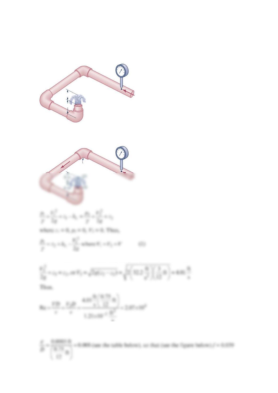
As shown in the figure below, water “bubbles up” 3 in. Above the exit of the vertical pipe
attached to three horizontal pipe segments. The total length of the 0.75-in.-diameter
galvanized iron pipe between point (1) and the exit is 21 in. Determine the pressure needed
at point (1) to produce this flow.
Solution 8.71
With no head loss from (3) to (2) and p2 = p3 = V2 = 0 we obtain
and
4 in.
3 in.
(1)
(1)
V
K
L = 1.5
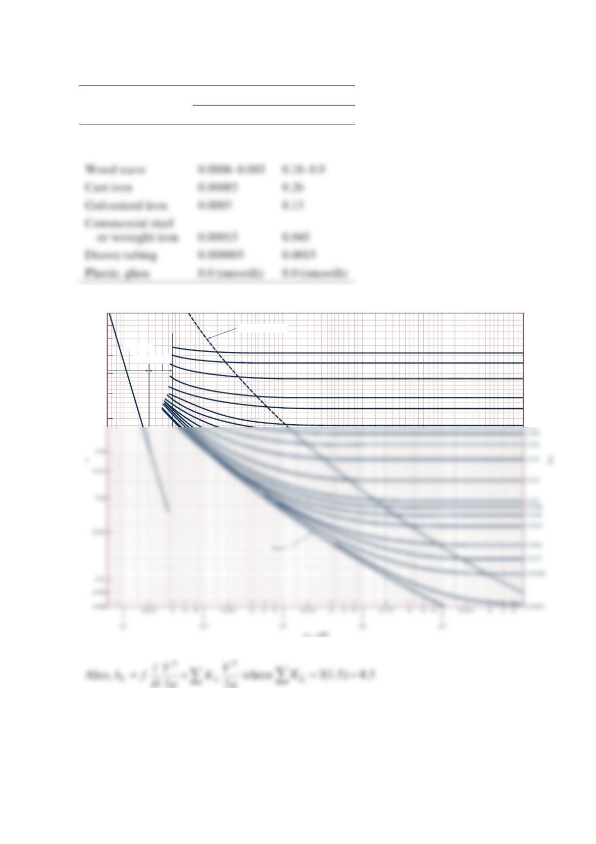
Equivalent Roughness for New Pipes [Adapted from Moody (Ref. 7) and Colebrook (Ref. 8)]
Equivalent Roughness,
ε
Pipe Feet Millimeters
Riveted steel 0.003–0.03 0.9–9.0
Concrete 0.001–0.01 0.3–3.0
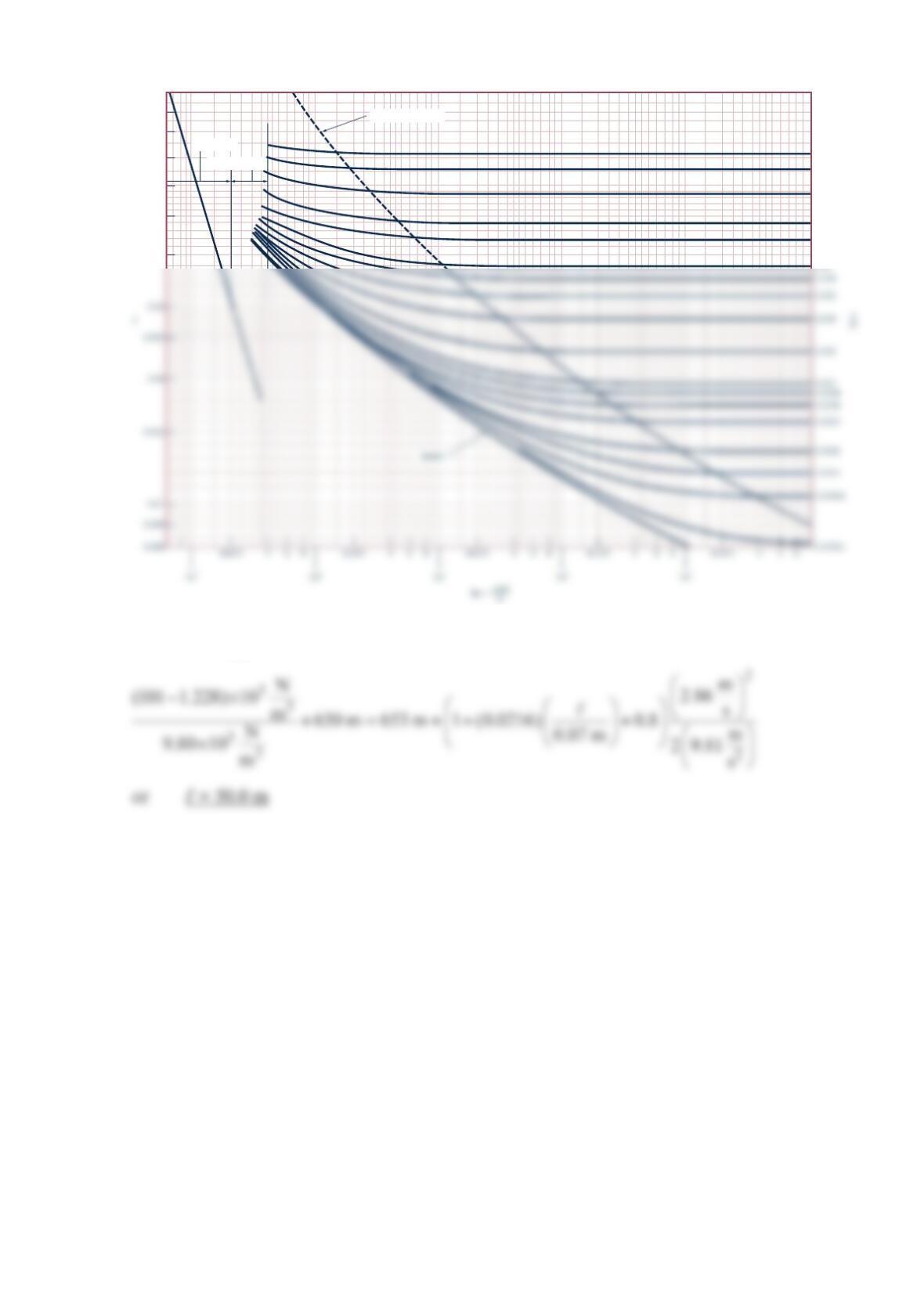
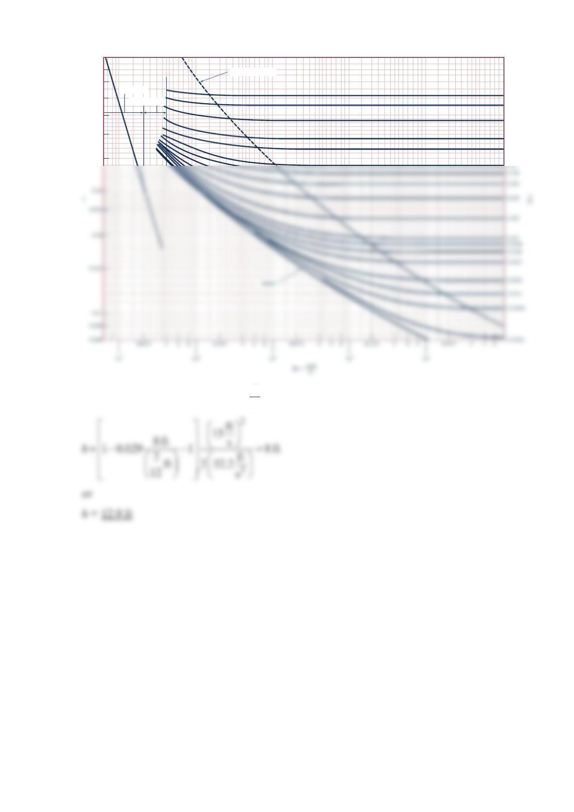
Transition range
Laminar flow
Wholly turbulent flow
0.1
0.09
0.08
0.07
0.06
0.05
0.04
0.05
0.04
0.03
0.02
0.015
Re = VD
μ
Hence, Eq. (1) becomes
2
2
11
21
where
22
L
pV
V
zf K VV
bgg
γ
=+ + − =
or
2
Problem 8.72
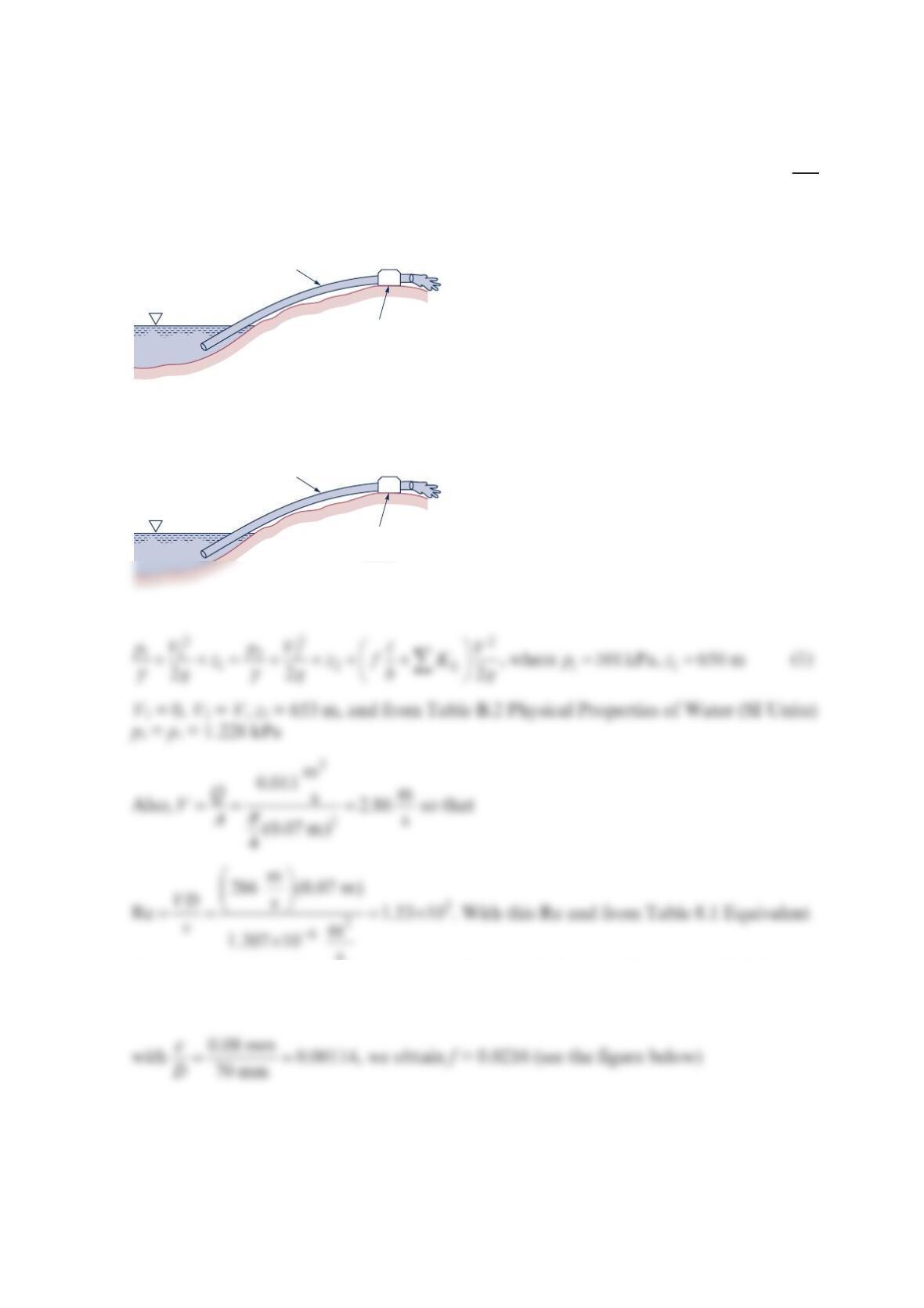
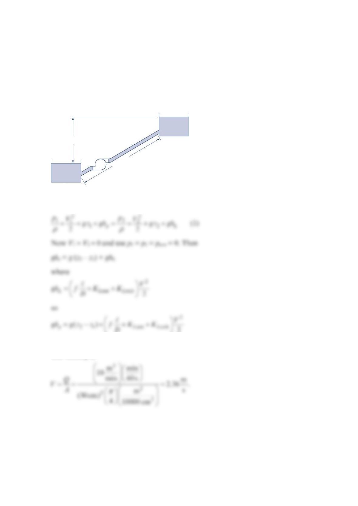
Water at 10°C is pumped from a lake as shown in the figure. If the flowrate is
3
m
0.011 s,
what is the maximum length inlet pipe, l, that can be used without cavitation occurring?
Solution 8.72
Roughness for New Pipes [Adapted from Moody (Ref. 7) and Colebrook (Ref. 8)]
Elevation
650 m
Elevation
653 m
Length 𝓵
D = 0.07 m
= 0.08 mm
Q =
0.011 m
3
/s
ε
Elevation
650 m
Elevation
653 m
Length 𝓵
D
= 0.07 m
= 0.08 mm
Q
=
0.011 m3/s
ε
(1)
•
(2)
•
Hence, with 0.8
L
K=
for the entrance, Eq. (1) becomes
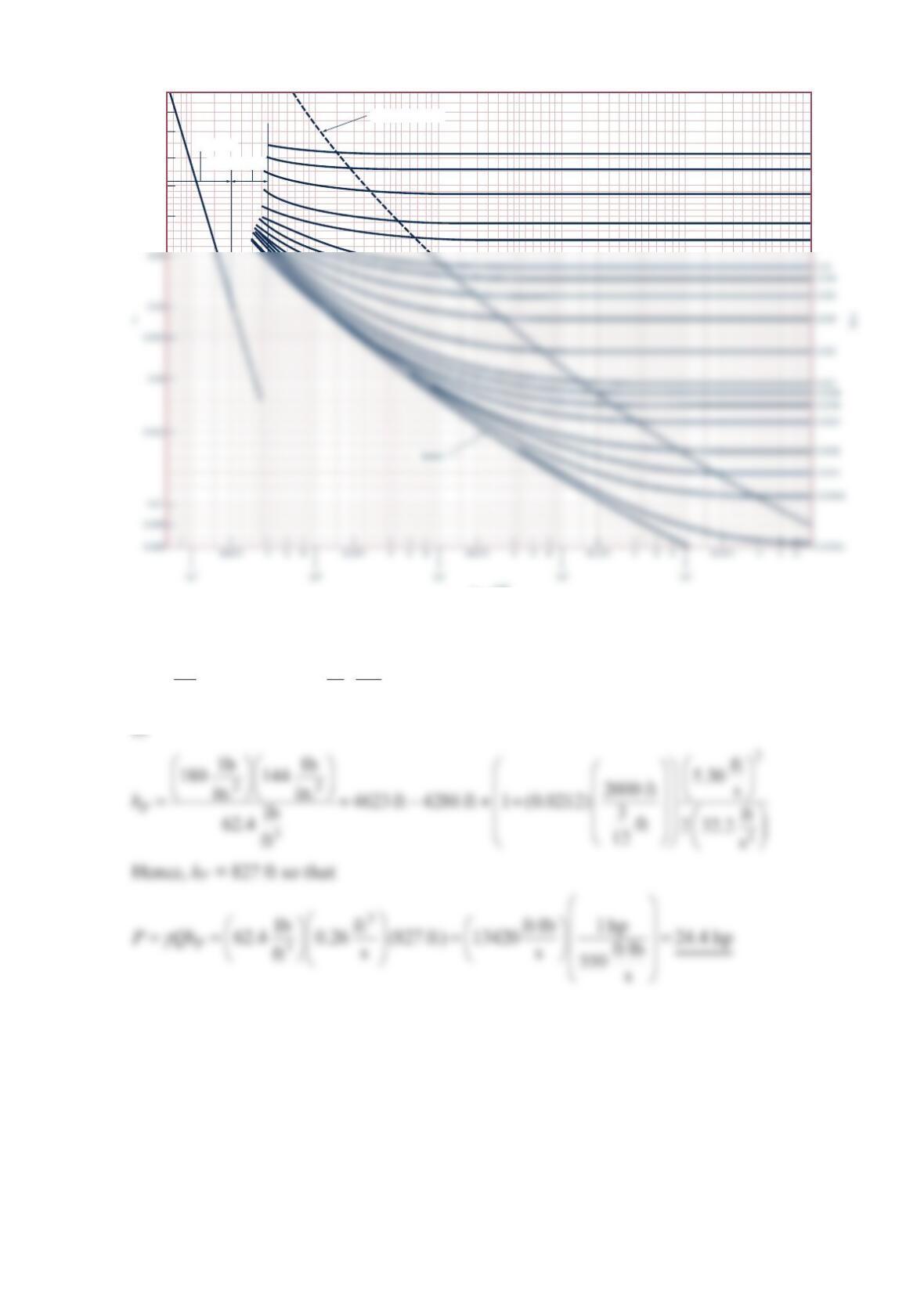
Transition range
Laminar flow
Wholly turbulent flow
0.1
0.09
0.08
0.07
0.06
0.05
0.04
0.05
0.04
0.03
0.02
0.015
Problem 8.73
At a ski resort, water at 40 F
is pumped through a
3
-in.-diameter,
2
000-ft-long steel pipe
from a pond at an elevation of 4286 ft to a snow-making machine at an elevation of 4623 ft
at a rate of
3
ft
0.26 .
s If it is necessary to maintain a pressure of
1
80 psi at the snow-making
machine, determine the horsepower added to the water by the pump. Neglect minor losses.
Solution 8.73
Equivalent Roughness for New Pipes [Adapted from
Moody (Ref. 7) and Colebrook (Ref. 8)]
Equivalent Roughness,
ε
Pipe Feet Millimeters
Riveted steel 0.003–0.03 0.9–9.0
Concrete 0.001–0.01 0.3–3.0
pump (2)
Thus, from Eq. (1)
=+−++
2
22112
P
pV
hzzf
Dg
γ
Transition range
Laminar flow
Wholly turbulent flow
0.1
0.09
0.08
0.07
0.06
0.05
0.05
0.04
0.03
0.02
0.015
Re = VD
_____
μ
ρ
Problem 8.74
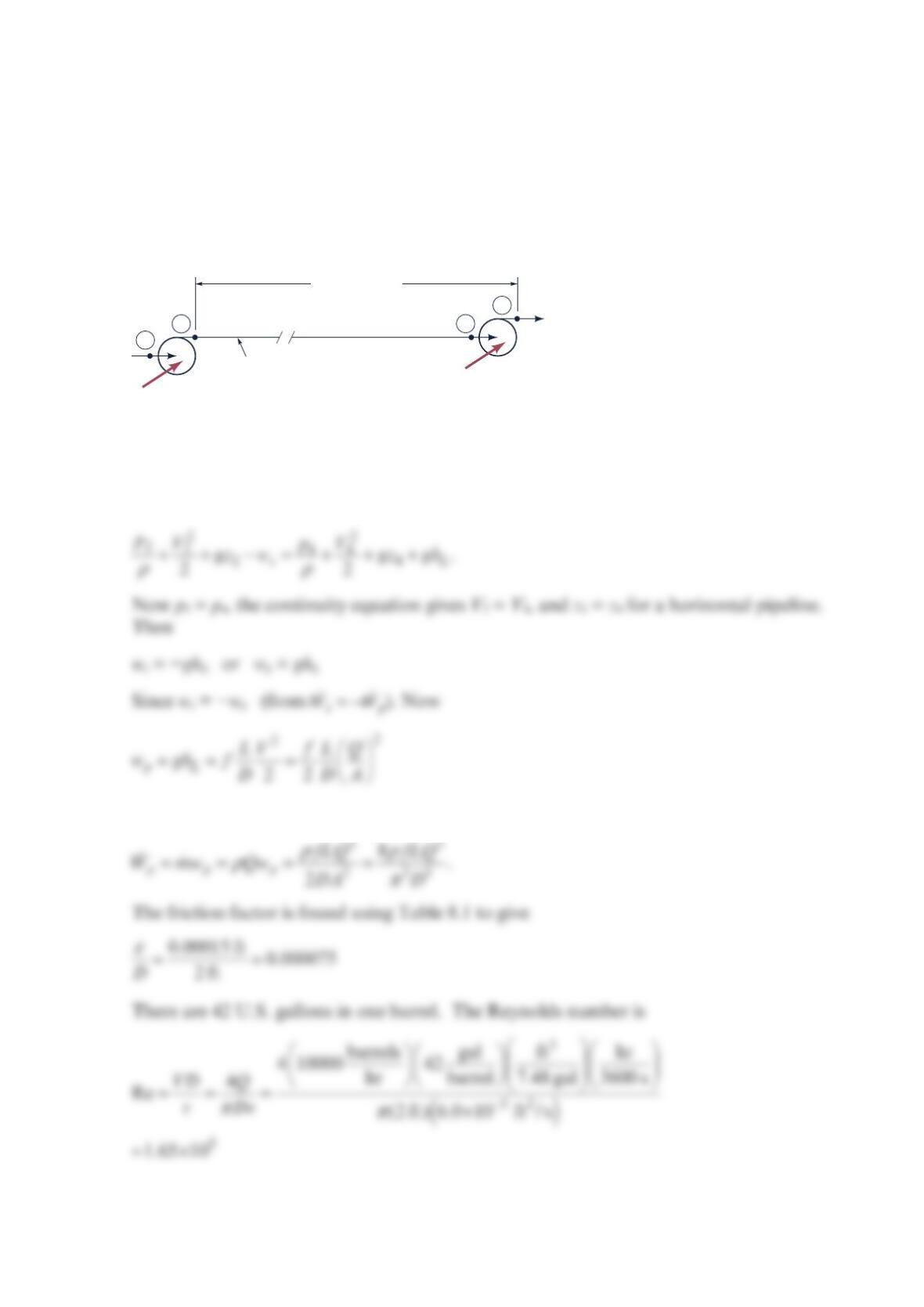
Crude oil having a specific gravity of 0.80 and a viscosity of 6.0 × 10⁻⁵ ft2/s flows through a
pumping station at a rate of 10000 barrels/hr. The oil then flows through 120000 ft of 24-in.
ID, horizontal, commercial steel pipe, enters another pumping station at 20 psig, and leaves
at a discharge pressure equal to the discharge pressure of the previous pumping station.
Calculate the discharge pressures and the power supplied to the crude oil at the second
pumping station. See the figure below.
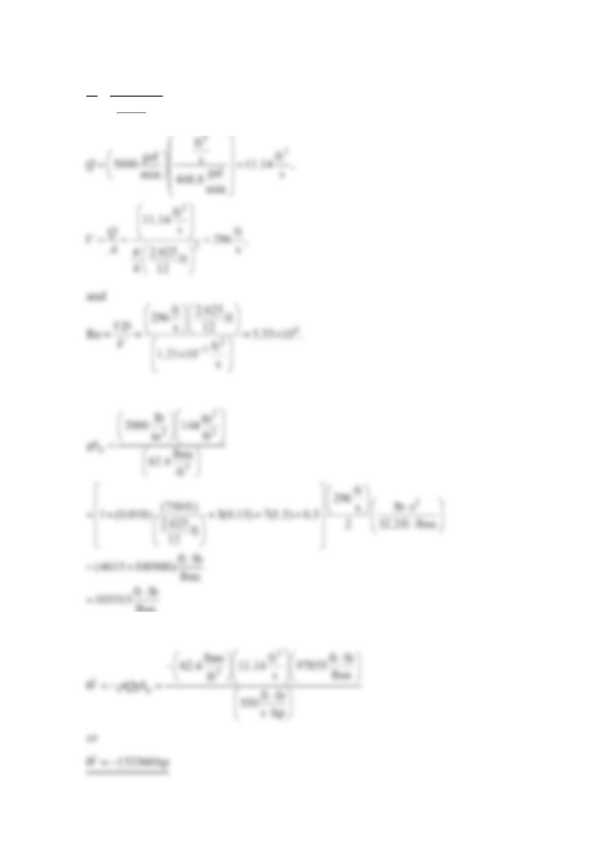
Solution 8.74
Assume constant oil density and apply the mechanical energy equation from point 2 to
point 4.
and
W
p
L
= 120000 ft
I.D. = 24 in. = 2 ft
1
23
4
·W
p
·
The Moody chart gives f = 0.016. Then
2
lb s
⋅
or
520hp
p
W=
.
The pressure at point 2 (or 4) is found by applying the mechanical energy equation between
points 2 and 3.
Problem 8.75
A motor-driven centrifugal pump delivers 15°C water at the rate of 10 m3/min from a
reservoir, through a 2500-m-long, 30-cm I.D. plastic pipe, to a second reservoir. The water
level in the second reservoir is 40 m above the water level in the first reservoir. The pump
efficiency is 75%. Find the motor output power. The pipe entrance is square edged.
Solution 8.75
Assume constant density. Write the mechanical energy equation from (1) to (2) with ht = 0
to get
For a square-edged entrance, Fig. 8.22 and Section 8.4.2 give KLent = 0.50 and KLexit = 1.0.
The velocity is
2500 m
40 m
1
•
2
•
For 15°C water, interpolating Table B.2 gives
The Moody chart gives f = 0.013. The energy equation is
The motor output power is
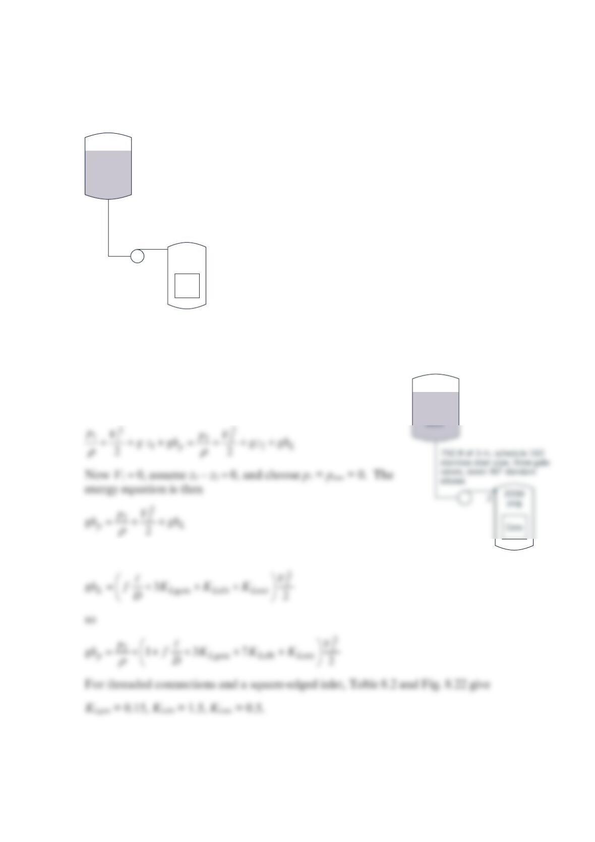
Problem 8.76
An emergency flooding system for a nuclear reactor core is shown in the figure below. Find
the power input required to flood the core at the rate of 5000 gal/min. Assume a square-
edged entrance, 60°F water, and threaded connections.
Solution 8.76
Assume constant density. Write the mechanical energy
equation from the reservoir level 1 to the pipe discharge
2 with t
h
= 0 to get
where
p
atm
50000
gallons
water
2000
psig
750 ft of 3-in. schedule 160 stainless
steel pipe (actual I.D. is 2.625 in.), three
gate valves, seven 90° regular elbows
Core
p
atm
50000
gallons
• 1
Tables 8.1 and B.1 for 60 °F water give
0.00015 ft 0.000686
2.625 ft
12
D
ε
==
The Moody chart gives f = 0.018. The energy equation gives
The power input (to the water) is
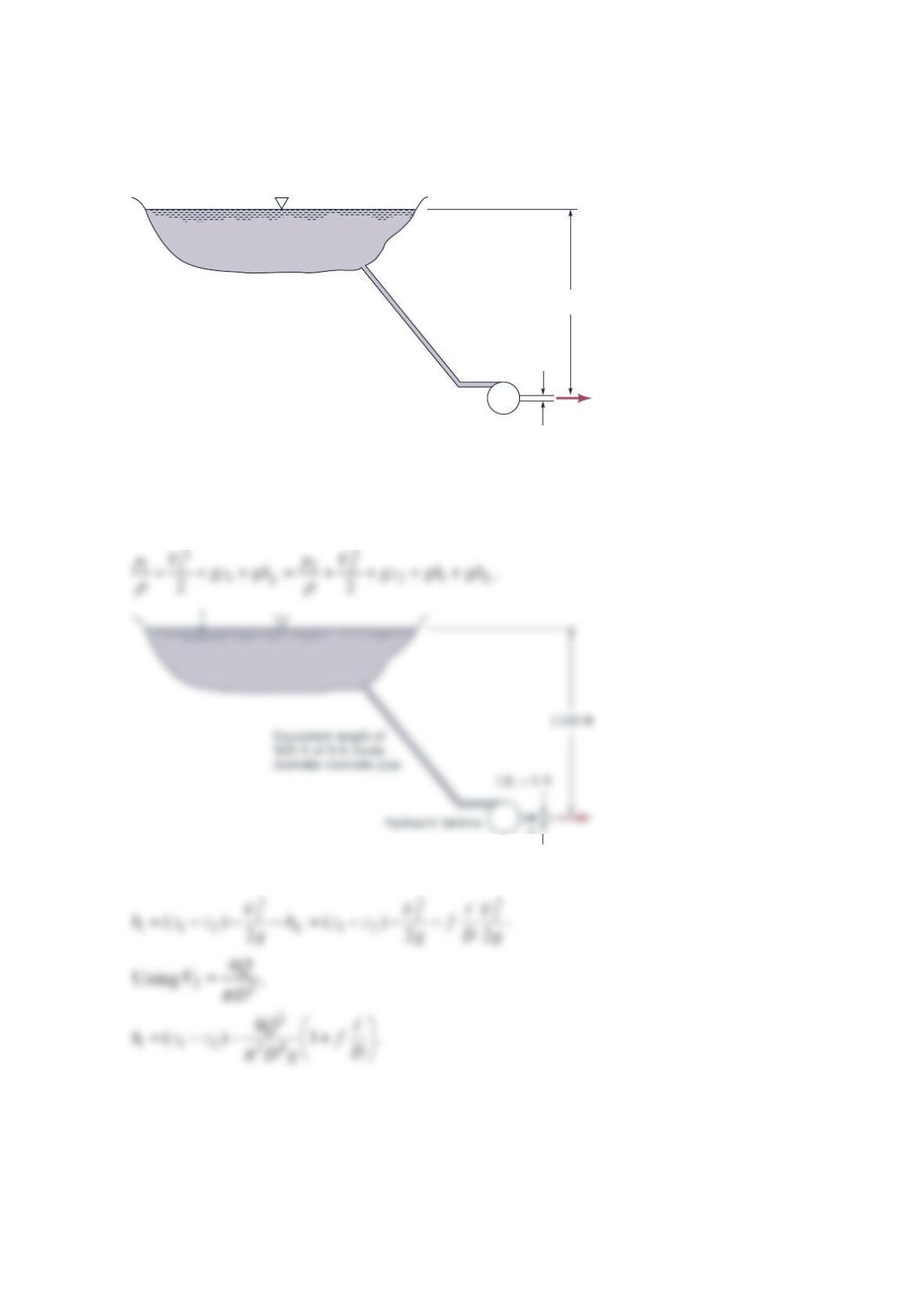
Problem 8.77
A hydraulic turbine takes water from a lake with the piping system shown in the figure
below. Find the head ht available to the turbine for flowrates of 0, 5000, 10000, 15000, and
20000 ft3/min.
Solution 8.77
Assume constant fluid density and steady state. Apply the mechanical energy equation
from the lake’s water surface (1) to the turbine outlet (2).
Now p1 = p2 = patm, V1 ≈ 0, and hp = 0 to get
1100 ft
I.D. = 5 ft
Hydraulic turbine
Equivalent length of
900 ft of 5-ft inside
diameter concrete pipe
2
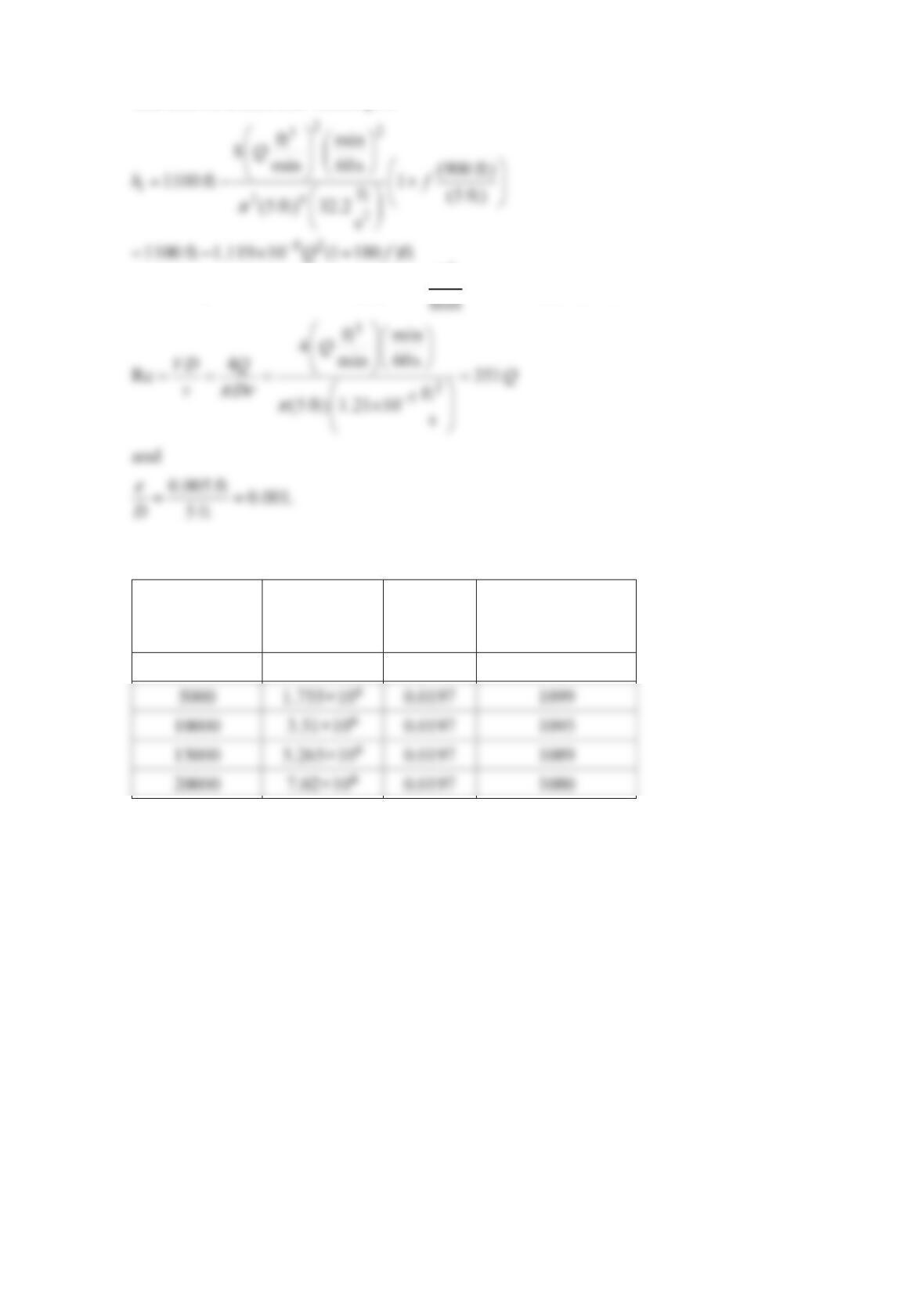
The known numerical values give
Assuming 60 °F water, noting Q is in
3
ft
Using the Moody chart, we tabulate the available turbine head t
h
versus Q.
Q
(ft3/min) Re f Available head,
ht (ft)
0 0 0.0198 1100
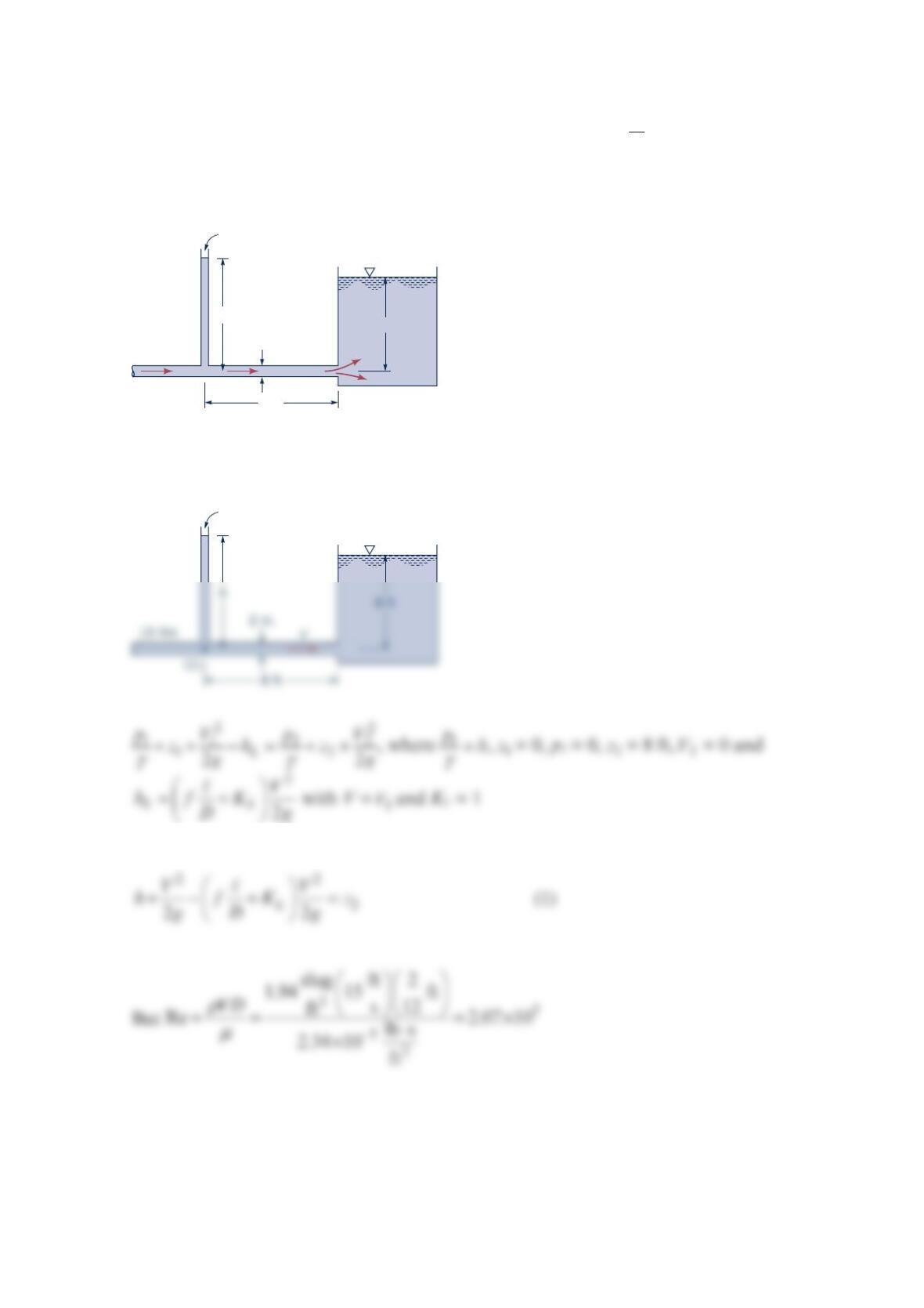
Problem 8.78
Water flows through a
2
-in.-diameter pipe with a velocity of ft
1
5s as shown in the figure
below. The relative roughness of the pipe is 0.004, and the loss coefficient for the exit is 1.0.
Determine the height, h, to which the water rises in the piezometer tube.
Solution 8.78
Thus
8 ft
8 ft
2 in.
15 ft/s
h
Open
Open
(2)
•
Hence from the figure above with 0.004
D
ε
=, we obtain f = 0.029 so that Eq. (1) becomes
Transition range
Laminar flow
Wholly turbulent flow
0.1
0.09
0.08
0.07
0.06
0.05
0.04
0.05
0.04
0.03
0.02
0.015
Problem 8.79
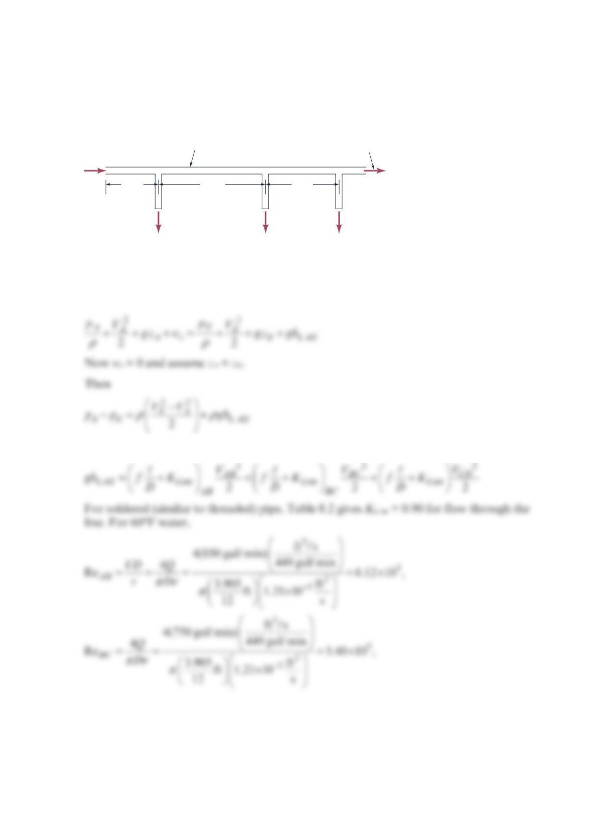
The figure below shows the 60°F water flowrates from the branches of a main supply line.
Find the total pressure drop (pA − pE) for soldered copper pipe. Assume that the loss
coefficient for each tee is based on the threaded type.
Solution 8.79
Assume constant density and steady state. Applying the mechanical energy equation from
A to E gives
where
A
Q
BCDE
70 ft 90 ft140 ft
Main supply line, 4-in.
type L copper pipe
(actual I.D. is 3.905 in.)
100 gal/min 150 gal/min 100 gal/min
500 gal/min
and
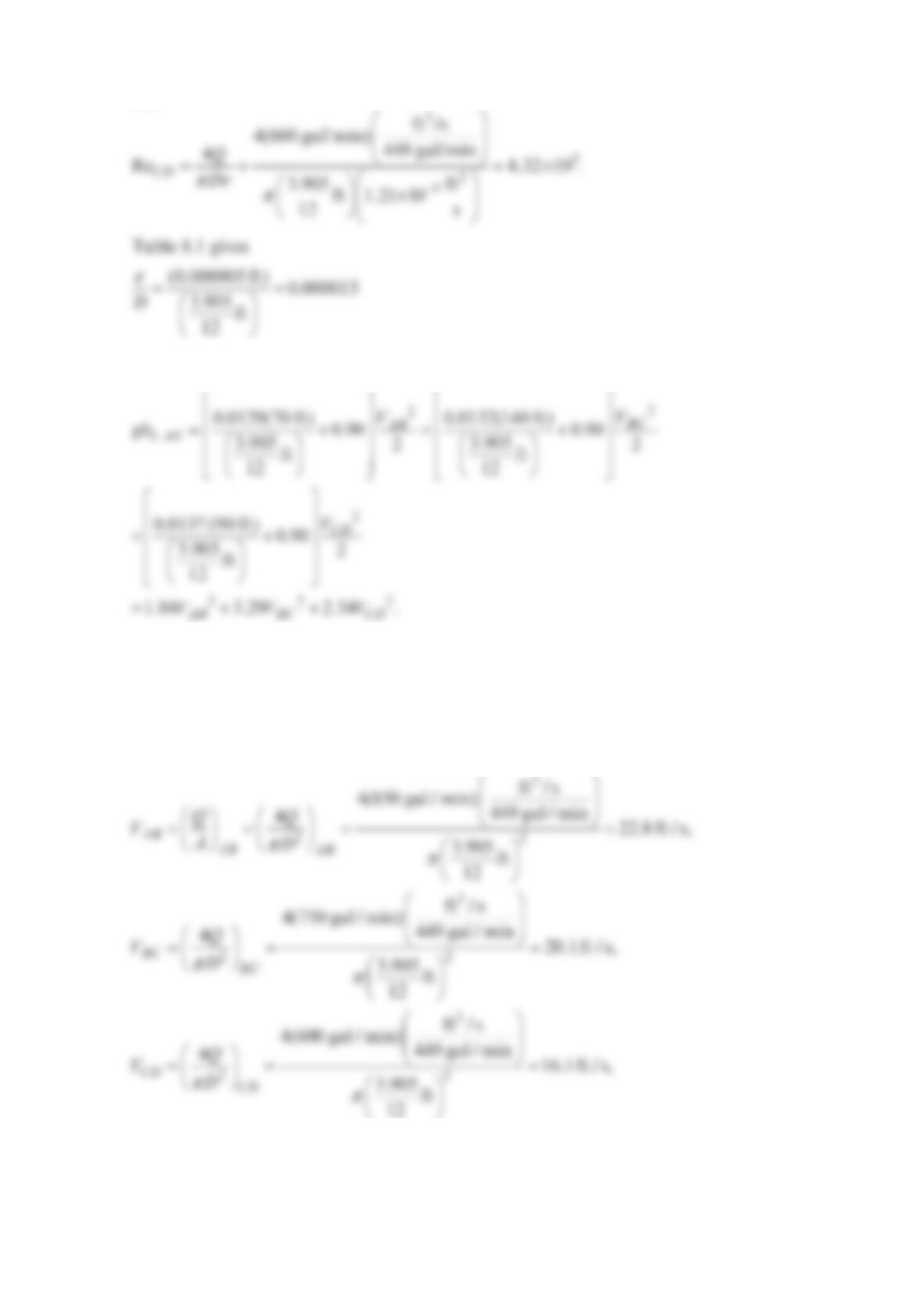
So the Moody chart gives fAB = 0.0129, fBC = 0.0132, fCD = 0.0137.
Since VA = VAB, the mechanical energy equation gives
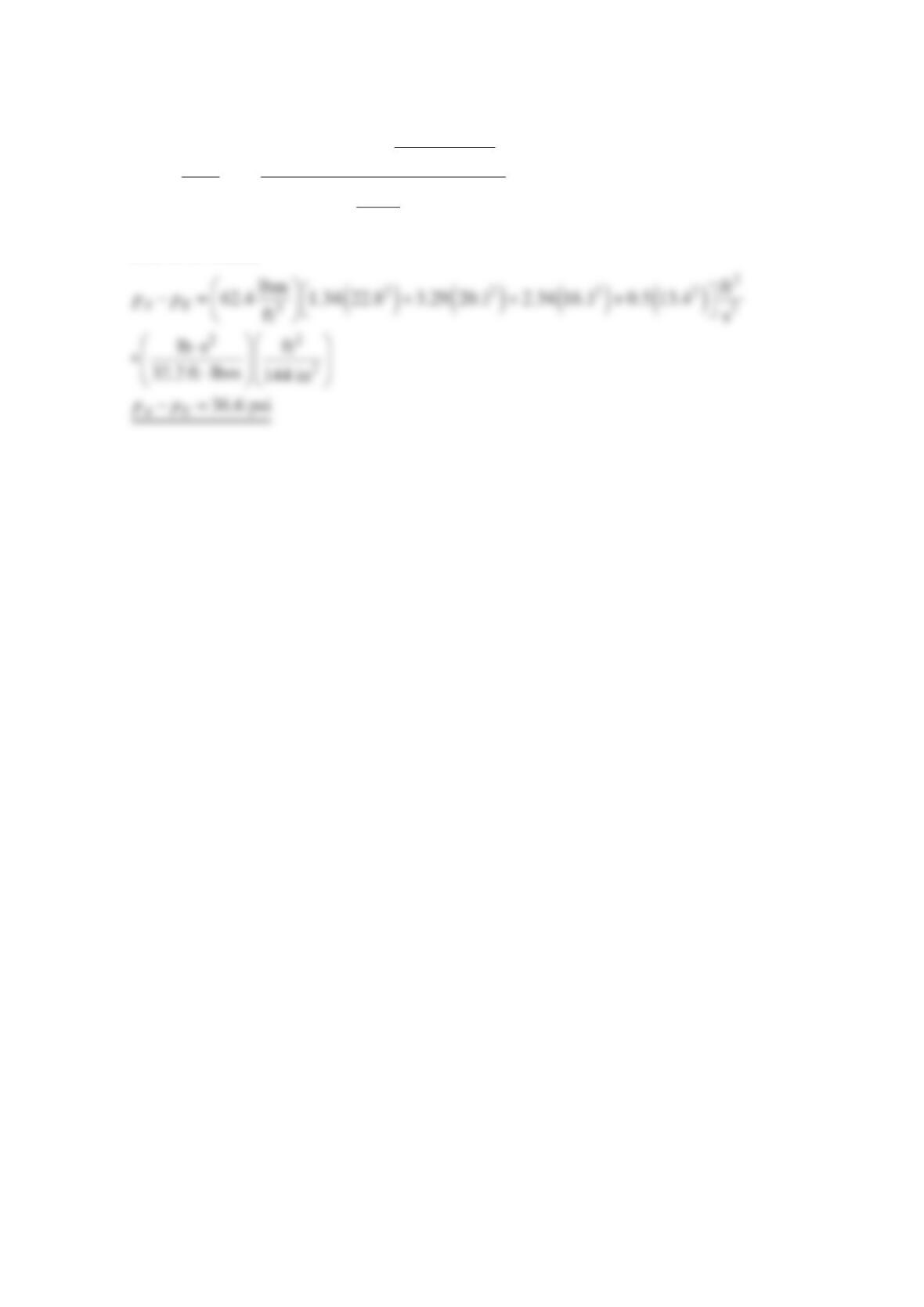
2222
(1.84 0.50) 3.29 2.34 0.5
A E AB BC CD E
p
pVVVV
ρ
−= − + + +
The velocities are
and
3
22
ft / s
4(500 gal / min) 449 gal / min
413.4 ft / s
3.905 ft
12
E
E
Q
V
D
ππ
== =
For 60°F water,