Chap. 7 Spread Footings: Geotechnical Ultimate Limit States
7.15 A certain column carries a vertical downward load of 1200 kN. It is to be supported on a 1 m
deep, square footing. The soil beneath this footing has the following properties: γ = 20.5 kN/m3,
cʹ=5 kPa,
φ
ʹ=36o. The groundwater table is at a depth of 1.5 m below the ground surface.
Using ASD, compute the footing width required for a factor of safety of 3.5.
Solution
Use Terzaghi’s method
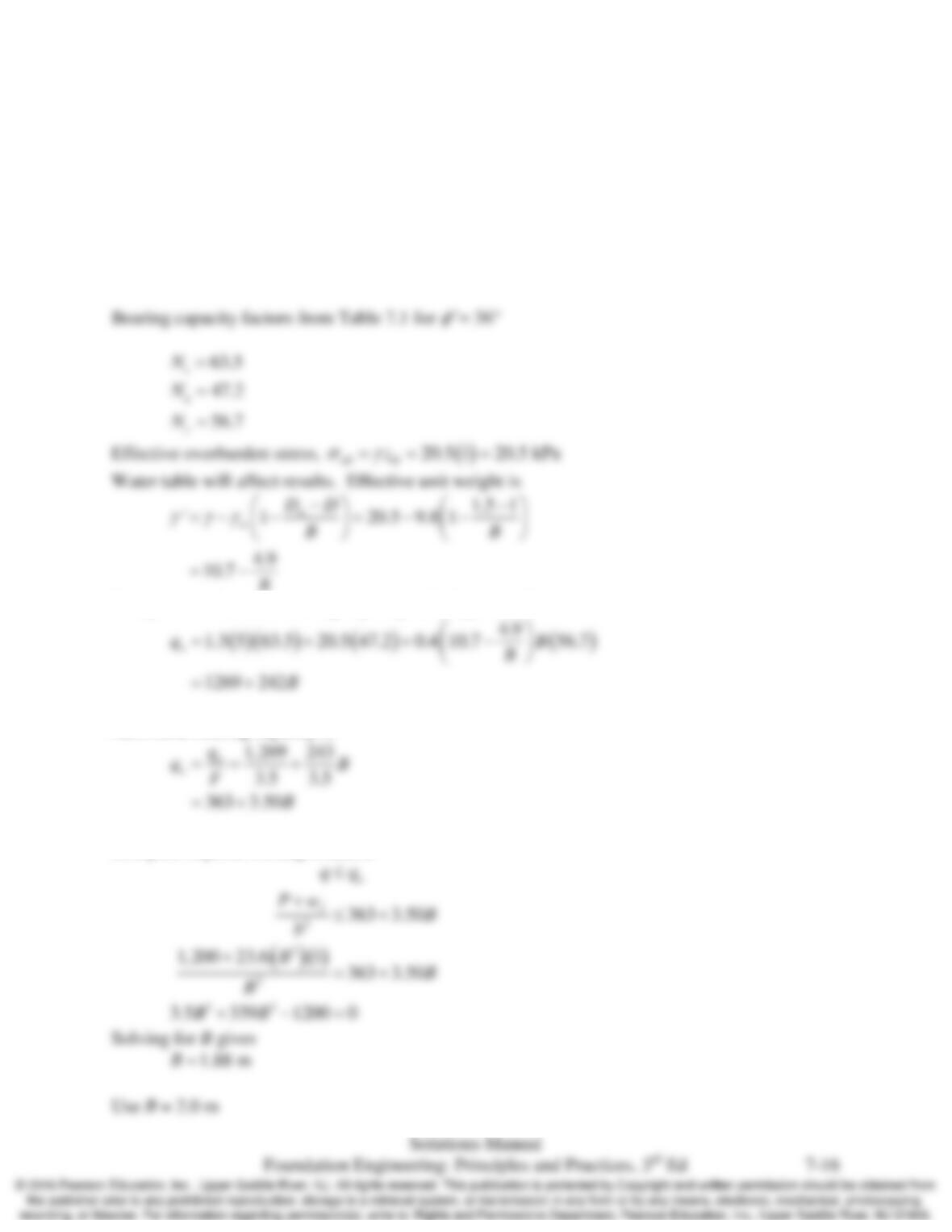
Compute nominal unit bearing capacity with Equation 7.4
Allowable bearing capacity is
Compute required footing width, B
Chap. 7 Spread Footings: Geotechnical Ultimate Limit States
7.16 A building column carries a factored ultimate vertical downward load of 320 k. It is to be
supported on a 3-ft deep, square footing. The soil beneath this footing has the following
properties: γ = 20.5 kN/m3, cʹ=5 kPa,
φ
ʹ =36°. The groundwater table is at a depth of 5 ft below
the ground surface. Using LRFD, with a resistance factor of 0.5, compute the required footing
width.
Solution
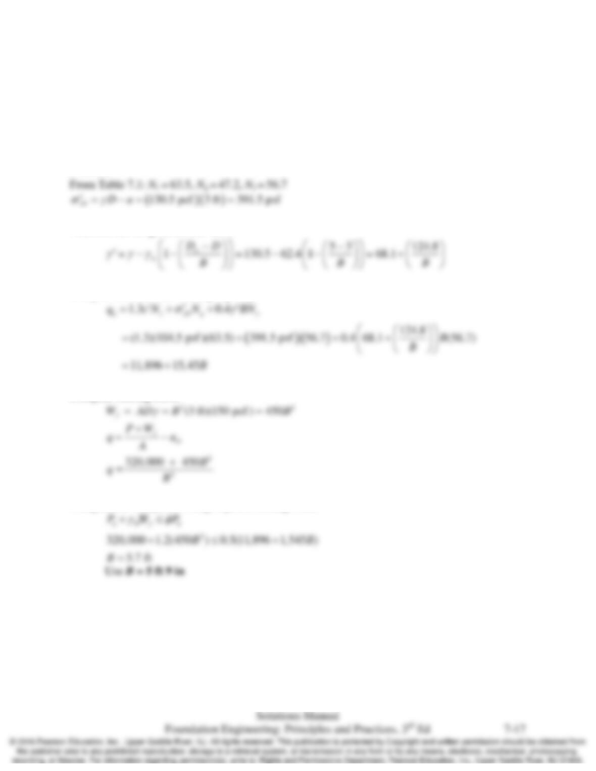
Must correct for groundwater table
Compute nominal unit bearing capacity
Compute bearing stress
Using LRFD compute footing required footing width
Chap. 7 Spread Footings: Geotechnical Ultimate Limit States
7.17 A 3–ft square footing is founded at a depth of 2.5 ft and carries an unfactored vertical column
load of 65 k. The underlying clay has an undrained shear strength of 1,500 lb/ft2. Compute the
allowable shear load this column can carry using ASD with a sliding factor of safety of 1.5
Solution
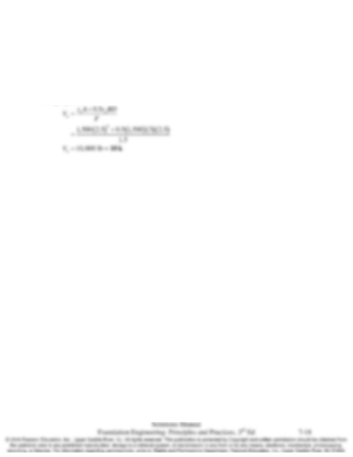
Using Equation 7.49:
7.18 A building column carries factored ultimate loads of 5,500 kN vertical and 1,200 kN horizontal.
The column is founded on 1.5-m square footing at a depth of 1.7 m. The soil is a cohesionless
sand with
φ
ʹ =32°, γ = 118.7 lb/ft3. Using LRFD with an active earth pressure load factor of 1.5
determine if this footing satisfies requirements for sliding.
Solution
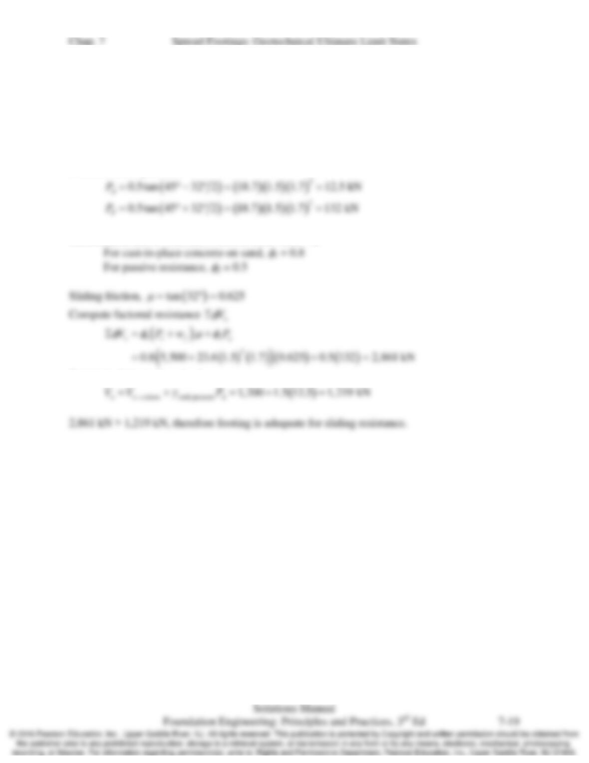
Calculate earth pressures
Geotechnical LRFD resistance factors, from Table 7.2
Compute ultimate shear load

Chap. 7 Spread Footings: Geotechnical Ultimate Limit States
7.19 Develop a spread sheet to compute allowable total vertical column loads using the ASD method
and factored ultimate vertical column loads using LRFD. The spreadsheet should consider only
vertical loads on a square or continuous footing bearing on single uniform soil. It should allow
the input of footing width, depth, water table depth, soil strength parameters, a Factor of safety
for ASD and a geotechnical resistance factor for LRFD. It should compute the bearing capacity
based on both Terzaghi’s and Vesić’s methods.
Solution
Chap. 7 Spread Footings: Geotechnical Ultimate Limit States
7.20 A certain column carries a vertical downward load of 424 k. It is to be supported on a 3-ft deep
rectangular footing. Because of a nearby property line, this footing may be no more than 5 ft
wide. The soil beneath this footing is a silty sand with the following properties: γ = 124 lb/ft3, cʹ
=50 lb/ft2,
φ
ʹ=34o. The groundwater table is at a depth of 6 ft below the ground surface. Using
ASD and the spreadsheet developed in Problem 7.19 to compute the footing length required for a
factor of safety of 3.0.
Solution
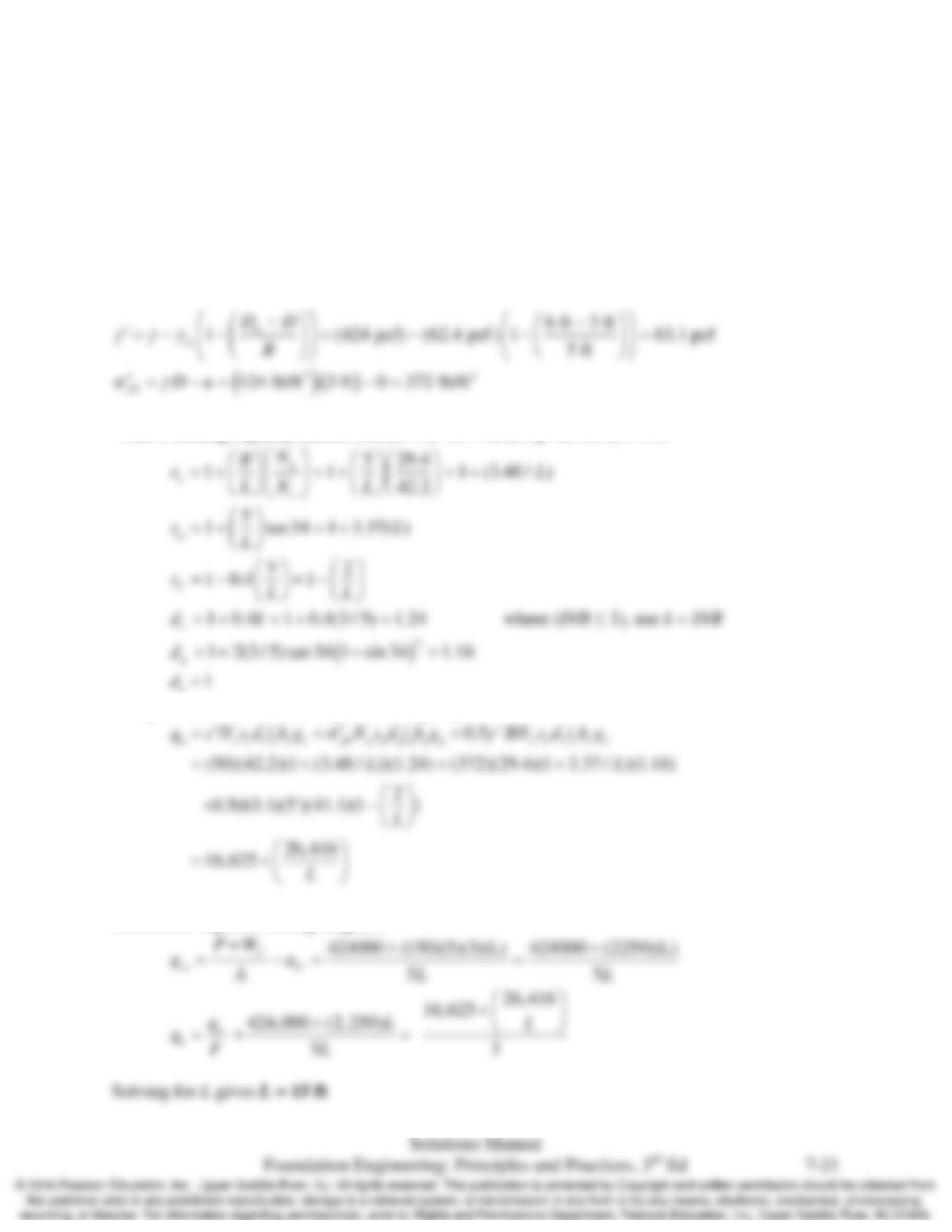
Vesić’s bearing capacity factors (Table 7.1) Nc= 42.2, Nq= 29.4, Nγ= 41.1
Compute nominal unit bearing stress using Equation 7.13
Determine required footing length, L
7.21 Repeat problem 7.20 using LRFD assuming the factored ultimate vertical column load is 560 k.
Solution
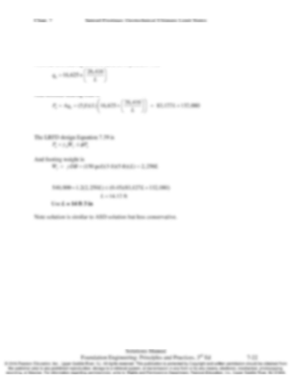
Nominal unit bearing stress is same as in problem 7.20
From Table 7.2, assume the LRFD resistance factor is 0.45
Chap. 7 Spread Footings: Geotechnical Ultimate Limit States
7.22 Conduct a bearing capacity analysis on the Fargo Grain Elevator (see sidebar) and back–calculate
the average undrained shear strength of the soil. The groundwater table is at a depth of 6 ft
below the ground surface. Soil strata A and B have unit weights of 110 lb/ft3; stratum D has 95
lb/ft3. The unit weight of stratum C is unknown. Assume that the load on the foundation acted
through the centroid of the mat.
Solution
For a
ϕ
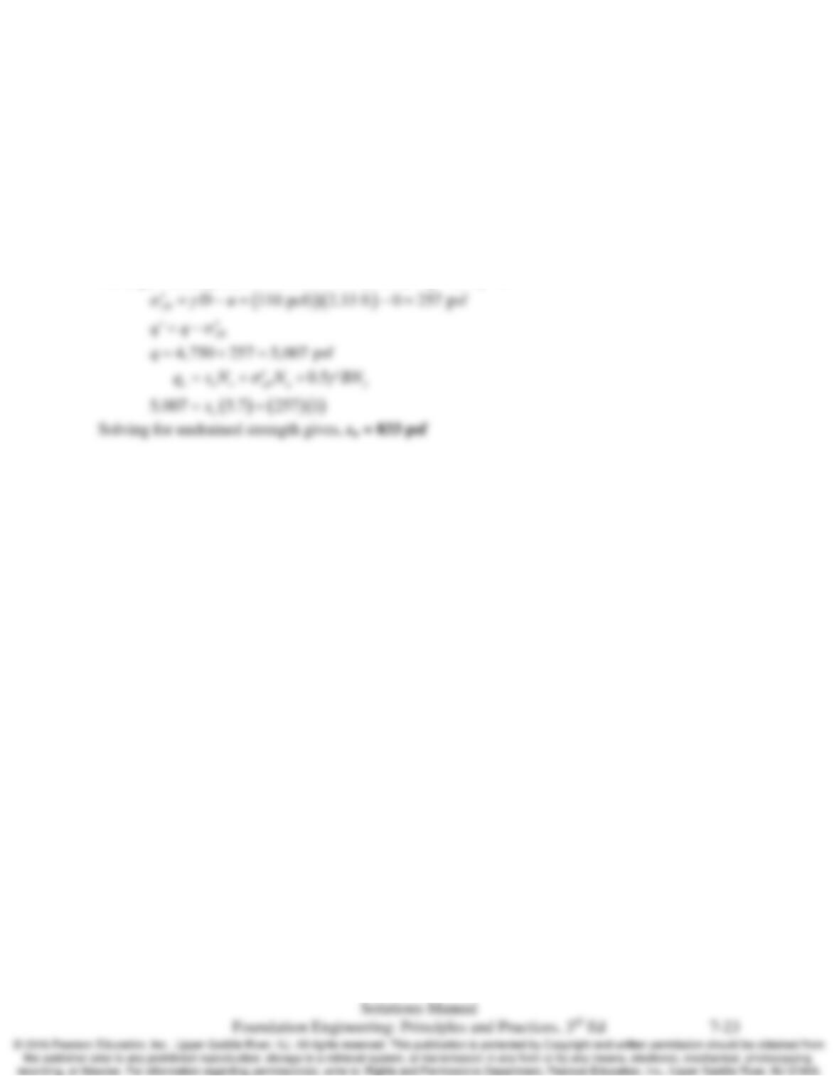
T= 0 analysis, from Table 7.1: Nc= 5.7, Nq= 1, Nγ= 0
Chap. 7 Spread Footings: Geotechnical Ultimate Limit States
7.23 Three columns, A, B, and C, are collinear, 500 mm in diameter, and 2.0 m on-center. They have
unfactored vertical downward loads of 1000, 550, and 700 kN, respectively, and are to be
supported on a single, 1.0 m deep rectangular combined footing. The soil beneath this proposed
footing has the following properties: γ = 19.5 kN/m3, cʹ=10 kPa, and
φ
ʹ= 31o. The groundwater
table is at a depth of 25 m below the ground surface.
(a) Using ASD, determine the minimum footing length, L, and the placement of the columns on
the footing that will place the resultant load at the centroid of the footing. The footing must
extend at least 500 mm beyond the edges of columns A and C.
(b) Using the results from part a., determine the minimum footing width, B, that will maintain a
factor of safety of 2.5 against a bearing capacity failure. Show the final design in a sketch.
Hint: Assume a value for B, compute the allowable bearing capacity, then solve for B. Repeat
this process until the computed B is approximately equal to the assumed B.
Solution
Part A
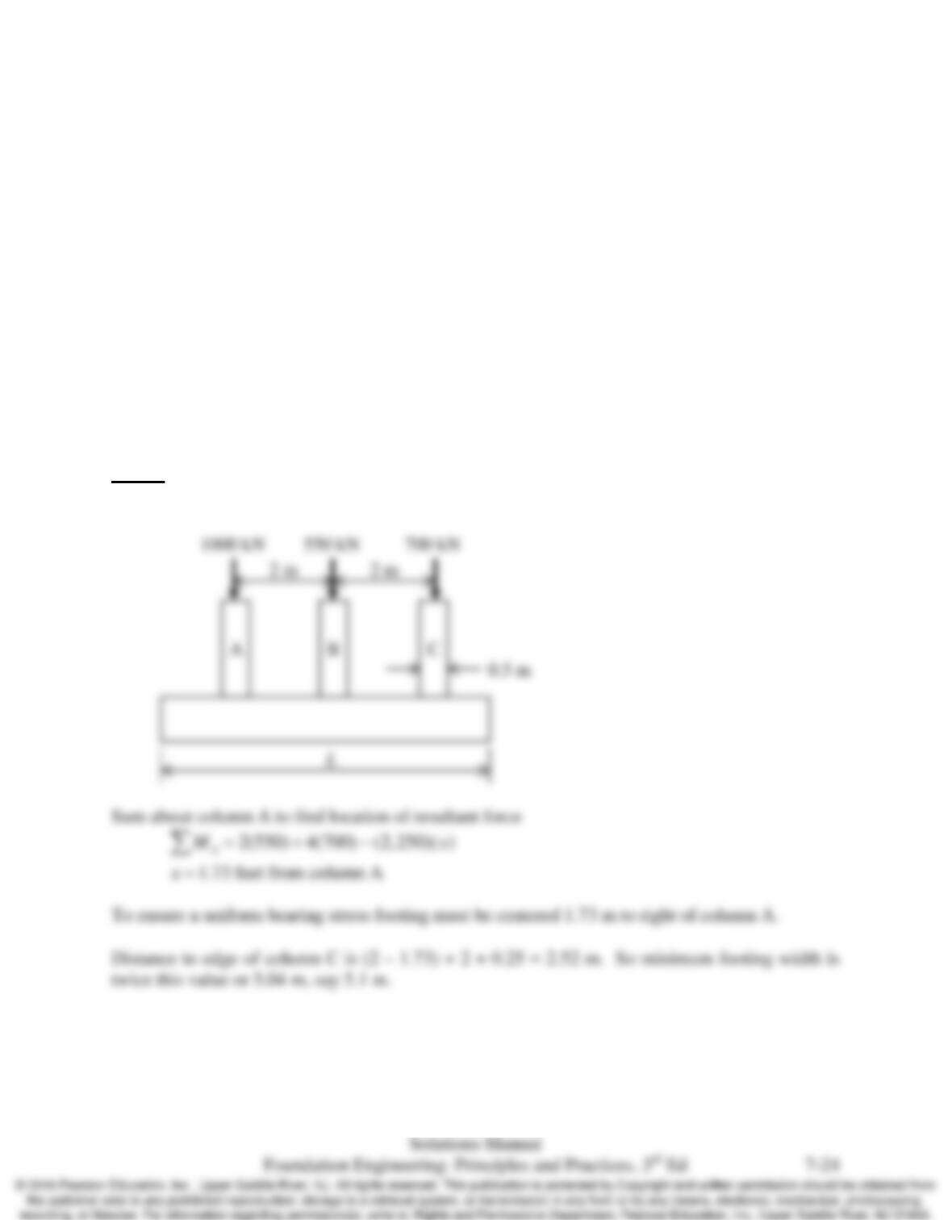
Column configuration is:
Chap. 7 Spread Footings: Geotechnical Ultimate Limit States
Part B
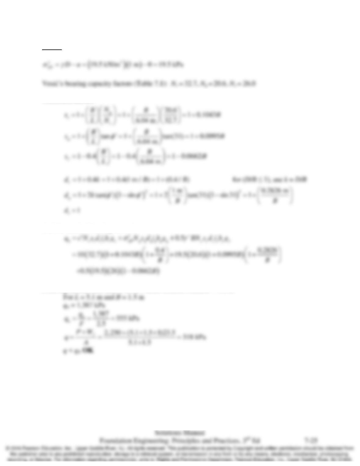
Correction factors
And the nominal bearing stress is:
From a practical limit take B to be 3 times column width, B = 1.5 m
Chap. 7 Spread Footings: Geotechnical Ultimate Limit States
7.24 Two columns, A and B, are to be built 6 ft 0 in apart (measured from their centerlines). Column
A has a vertical downward dead load and live loads of 90 k and 80 k, respectively. Column B
has corresponding loads of 250 k and 175 k. The dead loads are always present, but the live
loads may or may not be present at various times during the life of the structure. It is also
possible that the live load would be present on one column, but not the other.
These two columns are to be supported on a 4 ft 0 in deep rectangular spread footing founded on
a soil with the following parameters: γ = 122 lb/ft3,
φ
ʹ = 37°, and cʹ = 100 lb/ft2. The
groundwater table is at a very great depth. Use ASD in this problem.
(a) The location of the resultant of the loads from columns A and B depends on the amount of
live load acting on each at any particular time. Considering all of the possible loading
conditions, how close could it be to column A? To column B?
(b) Using the results of part a., determine the minimum footing length, L, and the location of the
columns on the footing necessary to keep the resultant force within the middle third of the
footing under all possible loading conditions. The footing does not need to be symmetrical.
The footing must extend at least 24 in beyond the centerline of each column.
(c) Determine the minimum required footing width, B, to maintain a factor of safety of at least
2.5 against a bearing capacity failure under all possible loading conditions.
(d) If the B computed in part c is less than the L computed in part b, then use a rectangular
footing with dimensions B × L. If not, then redesign using a square footing. Show your final
design in a sketch.
Solution
Part A
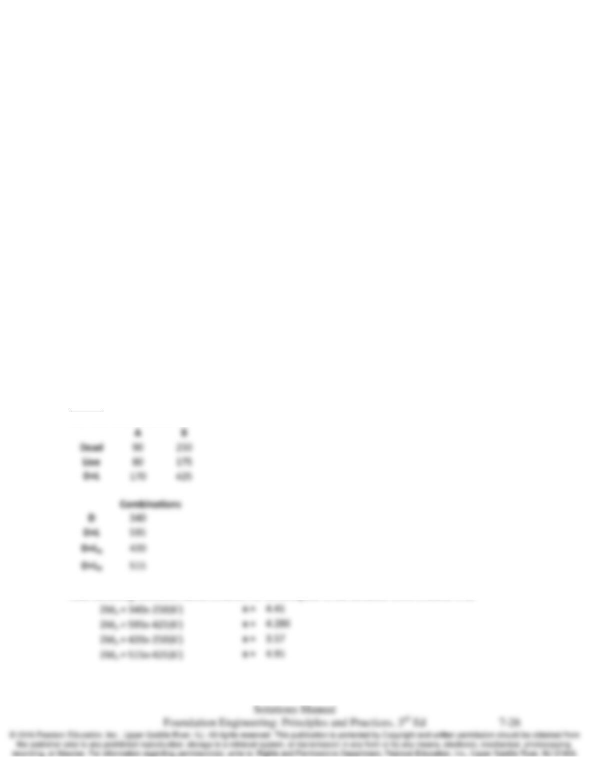
The load combinations are
And summing moments about column A, we compute x, the distance from column A as
Chap. 7 Spread Footings: Geotechnical Ultimate Limit States
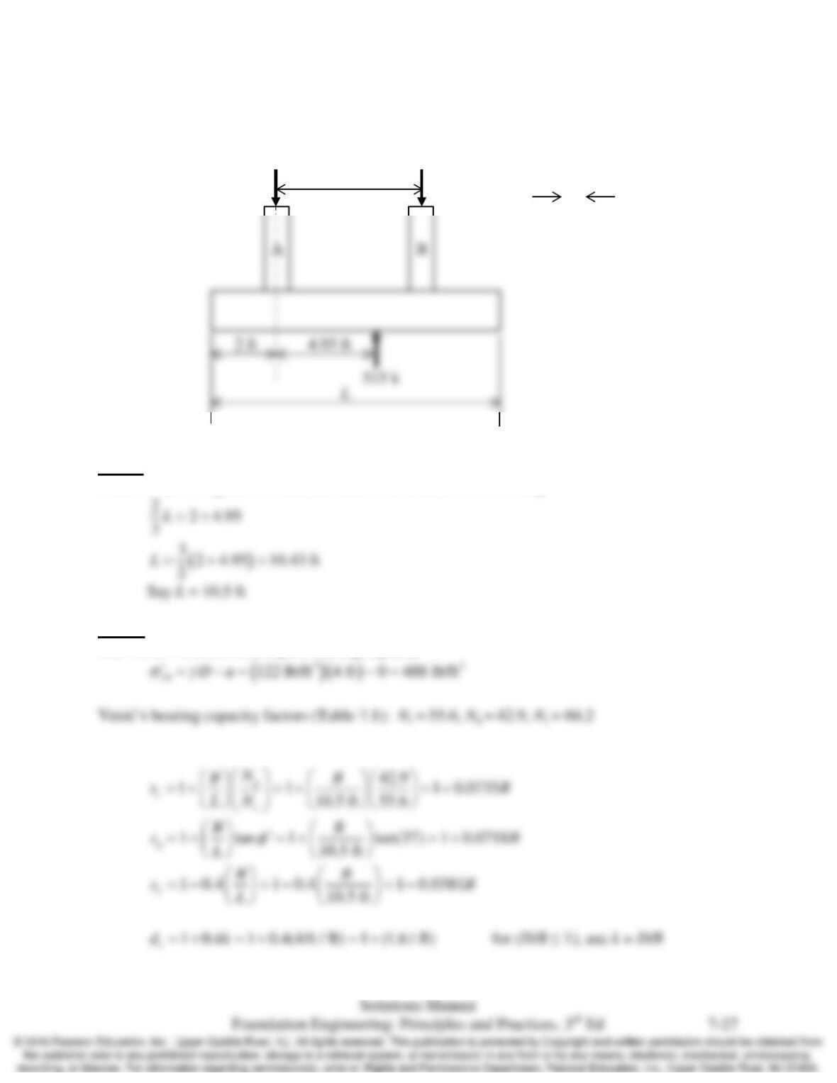
So the greatest eccentricity is x = 4.95 ft from column A or 1.05 ft from column B as shown
below.
Part B
From the above figure, for resultant load be in middle 1/3 of footing
Part C
Use Vesić’s method to compute bearing capacity
Correction factors
0.5 m
6 ft
90 k
425 k
515 k
Chap. 7 Spread Footings: Geotechnical Ultimate Limit States
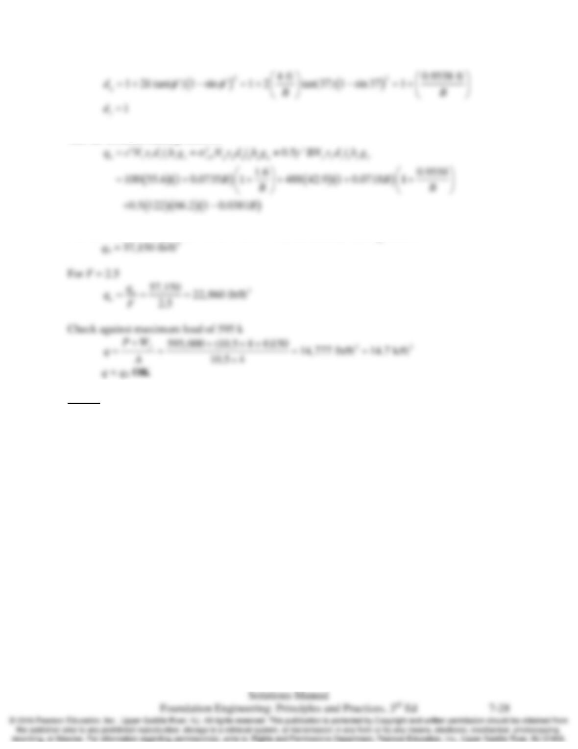
And the nominal bearing stress is:
The minimum footing width is 4 ft. For B = 4 ft, the nominal bearing stress is
Part D
No need to redesign. Final footing is 4 ft by 10 ft 6 in.
Chap. 7 Spread Footings: Geotechnical Ultimate Limit States
7.25 In May 1970, a 70 ft tall, 20 ft diameter concrete grain silo was constructed at a site in Eastern
Canada (Bozozuk, 1972b). This cylindrical silo, which had a weight of 183 tons, was supported
on a 3 ft wide, 4 ft deep ring foundation. The outside diameter of this foundation was 23.6 ft,
and its weight was about 54 tons. There was no structural floor (in other words, the contents of
the silo rested directly on the ground).
The silo was then filled with grain. The exact weight of this grain is not known, but was
probably about 533 tons. Unfortunately, the silo collapsed on September 30, 1970 as a result of
a bearing capacity failure.
The soils beneath the silo are primarily marine silty clays. Using an average undrained shear
strength of 500 lb/ft2, a unit weight of 80 lb/ft3, and a groundwater table 2 ft below the ground
surface, compute the ASD factor of safety against a bearing capacity failure, then comment on
the accuracy of the analysis, considering the fact that a failure did occur.
Solution
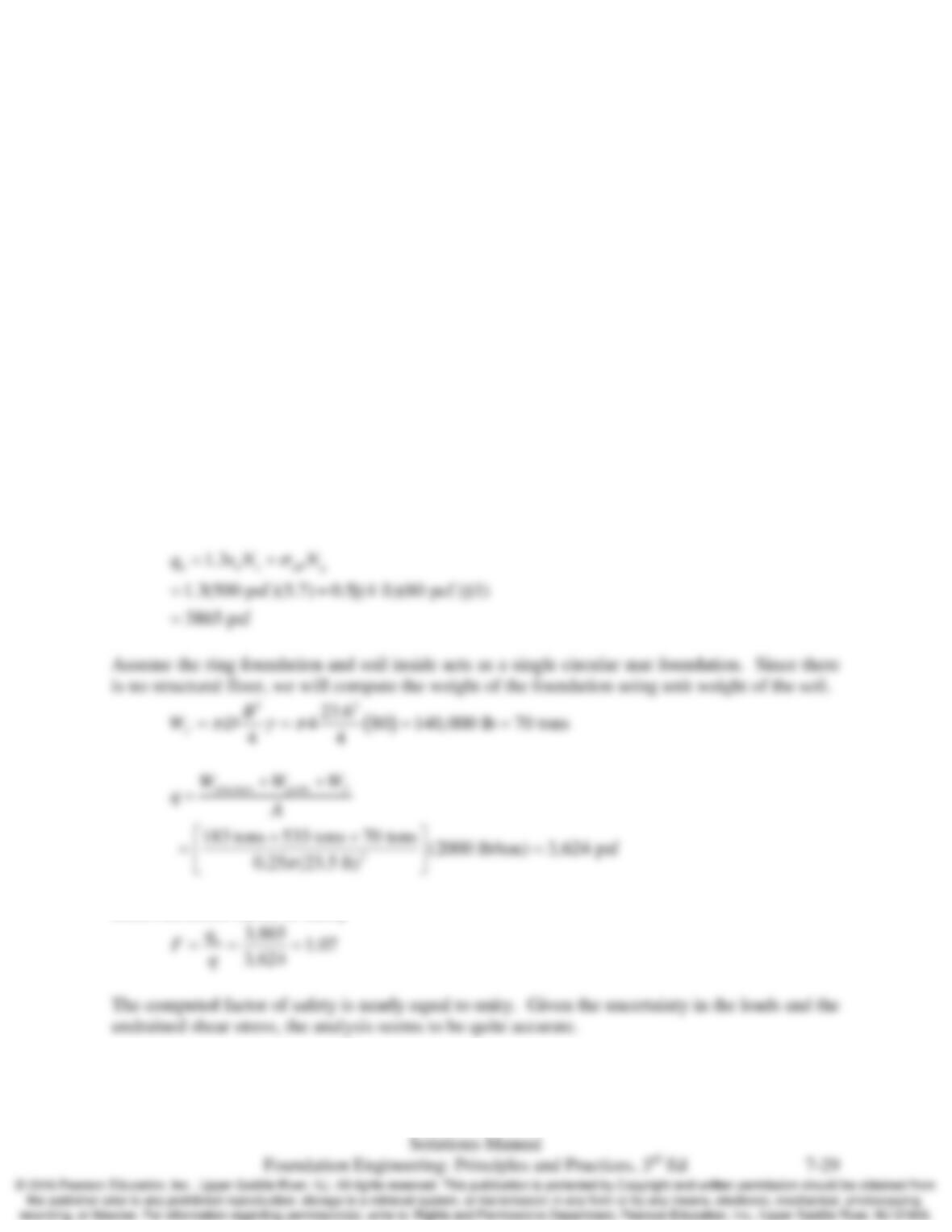
This is an undrained condition in a saturated clay so a total stress analysis is appropriate. For
this analysis the shear strength is defined as cT = su and ϕT = 0, and we ignore the groundwater
table. Using Terzaghi’s solution, from Table 7.1: Nc =5.7, Nq = 1.0, and Nγ = 0.0.
Back calculated factor of safety