
PROBLEM 7.35 (Cont.)
(b) When the tube is half full, the upper half of the tube will act as a fin. The total rate of heat loss per
unit mass will be qM = qM1 + qM2 where qM1 is the radial heat loss that is the same as in part (a) and qM2
is the heat loss to the upper half of the copper tubing, which serves as a fin. From part (a) qM1 = 185
W/kg. Assuming an infinite fin and recognizing that the cross-sectional area is associated with the
inner and outer diameters of the tubing,
COMMENTS: (1) The fin effect is significant, and the water in the half-full tube will freeze before
the water in the full tube. (2) The temperature distribution in the copper tubing above the water level in
the half-full tubing is
θ
/
θ
b = exp-mx where x is a local coordinate with origin at the water level. For this
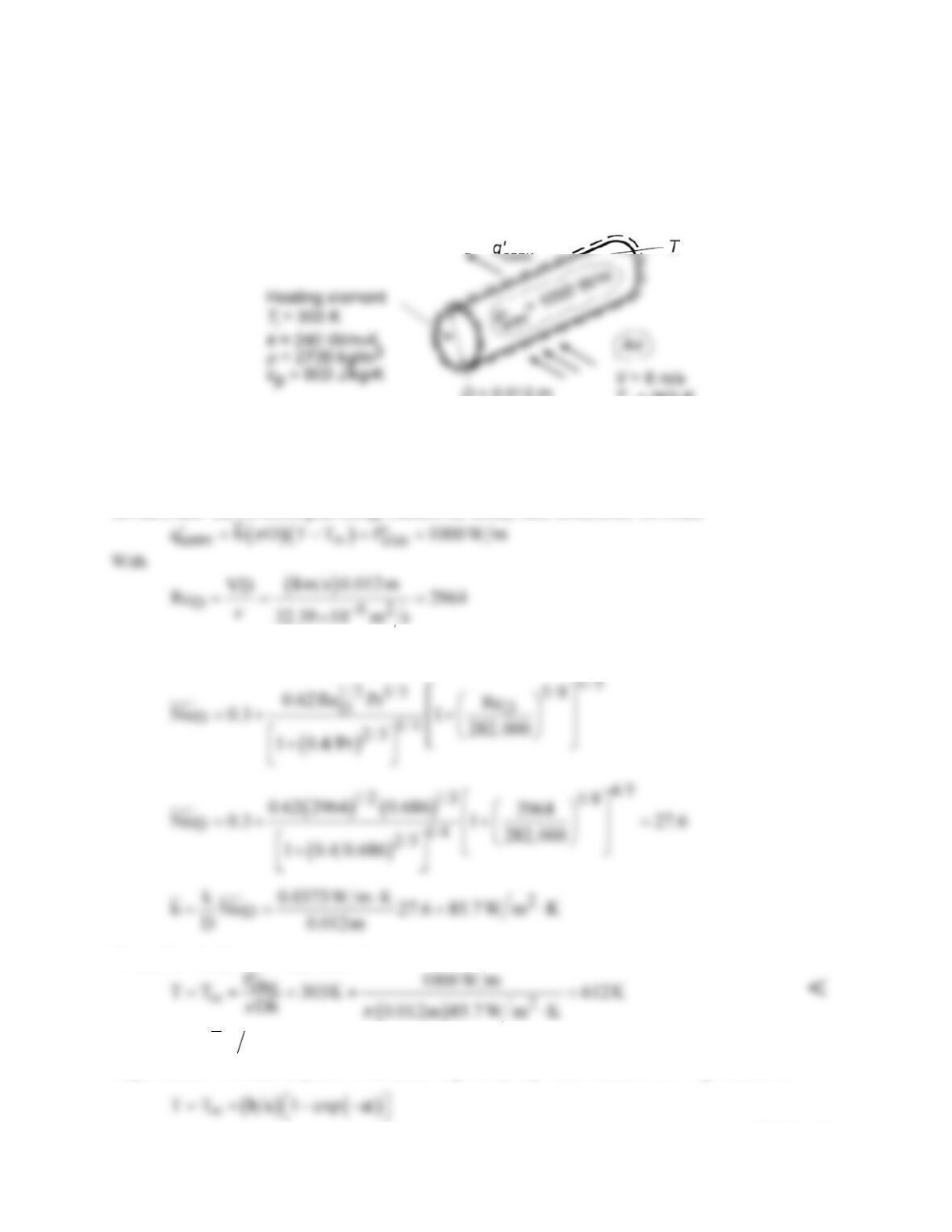
problem,
PROBLEM 7.36
KNOWN: Initial temperature, power dissipation, diameter, and properties of heating element. Velocity
and temperature of air in cross flow.
FIND: (a) Steady–state temperature, (b) Time to come within 10°C of steady–state temperature.
SCHEMATIC:
D= 0.012 m
T
∞
= 303 K
ASSUMPTIONS: (1) Uniform heater temperature, (2) Negligible radiation.
PROPERTIES: Table A.4, air (assume Tf ≈ 450 K): ν = 32.39 × 10⁻⁶ m2/s, k = 0.0373 W/m⋅K, Pr =
0.686.
ANALYSIS: (a) Performing an energy balance for steady–state conditions, we obtain
the Churchill and Bernstein correlation, Eq. 7.54, yields
Hence, the steady–state temperature is
(b) With Bi =
o
hr k
= 85.7 W/m2⋅K(0.006 m)/240 W/m⋅K = 0.0021, a lumped capacitance analysis may
be performed. The time response of the heater is given by Eq. 5.25, which, for Ti =
T
¥
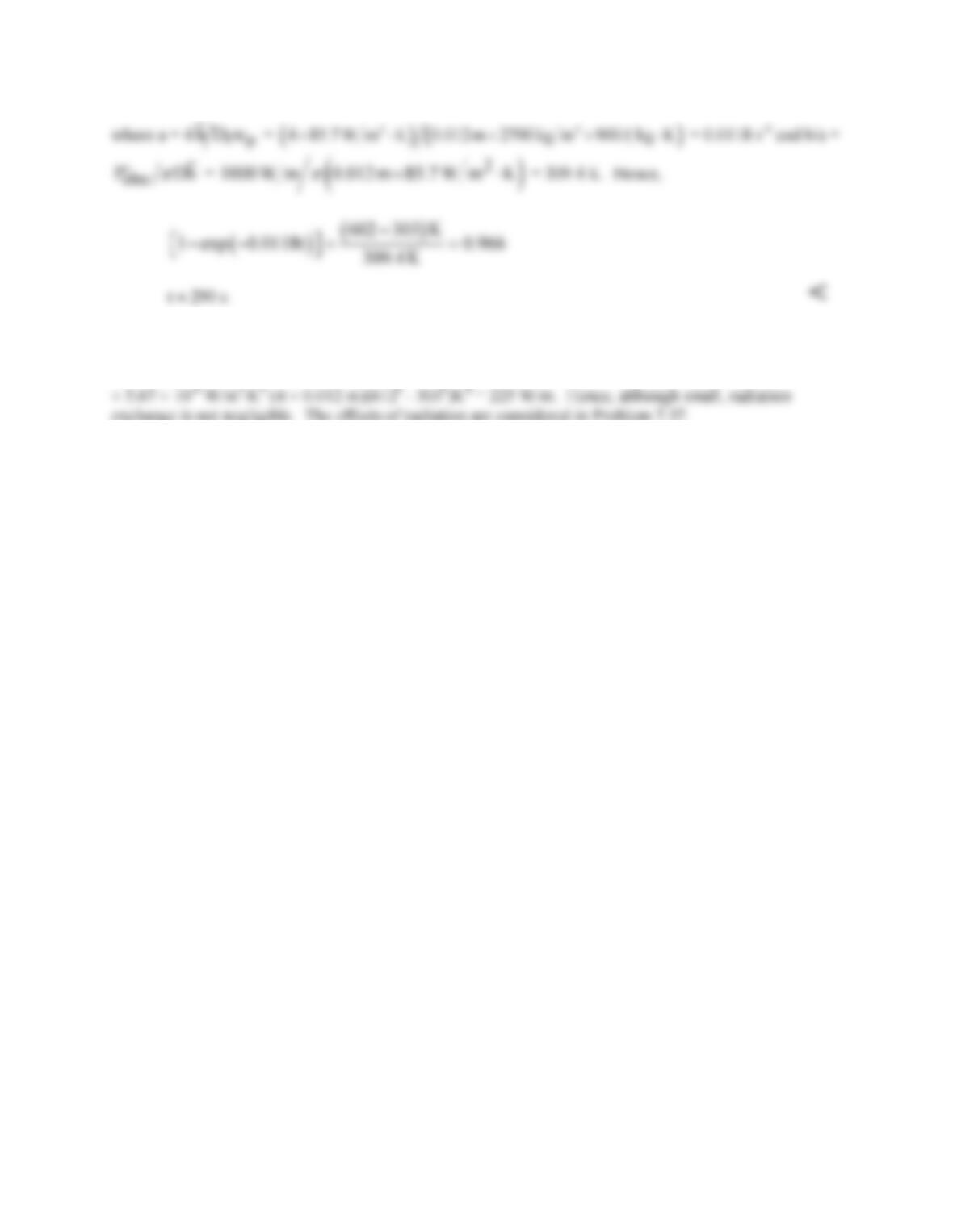
, reduces to
Continued…
PROBLEM 7.36 (Cont.)
COMMENTS: (1) For T = 612 K and a representative emissivity of ε = 0.8, net radiation exchange
between the heater and surroundings at Tsur =
T¥
= 303 K would be
( )
()
44
rad sur
q DT T
εs π
′= −
= 0.8
(2) The assumed value of Tf is very close to the actual value, rendering the selected air properties
accurate.
PROBLEM 7.37
KNOWN: Initial temperature, power dissipation, diameter, and properties of a heating element.
Velocity and temperature of air in cross flow. Temperature of surroundings.
FIND: (a) Steady–state temperature, (b) Time to come within 10°C of steady–state temperature, (c)
Variation of power dissipation required to maintain a fixed heater temperature of 275°C over a range of
velocities.
SCHEMATIC:
D= 0.012 m
T∞= 303 K
ASSUMPTIONS: (1) Uniform heater surface temperature, (2) Surroundings are large.
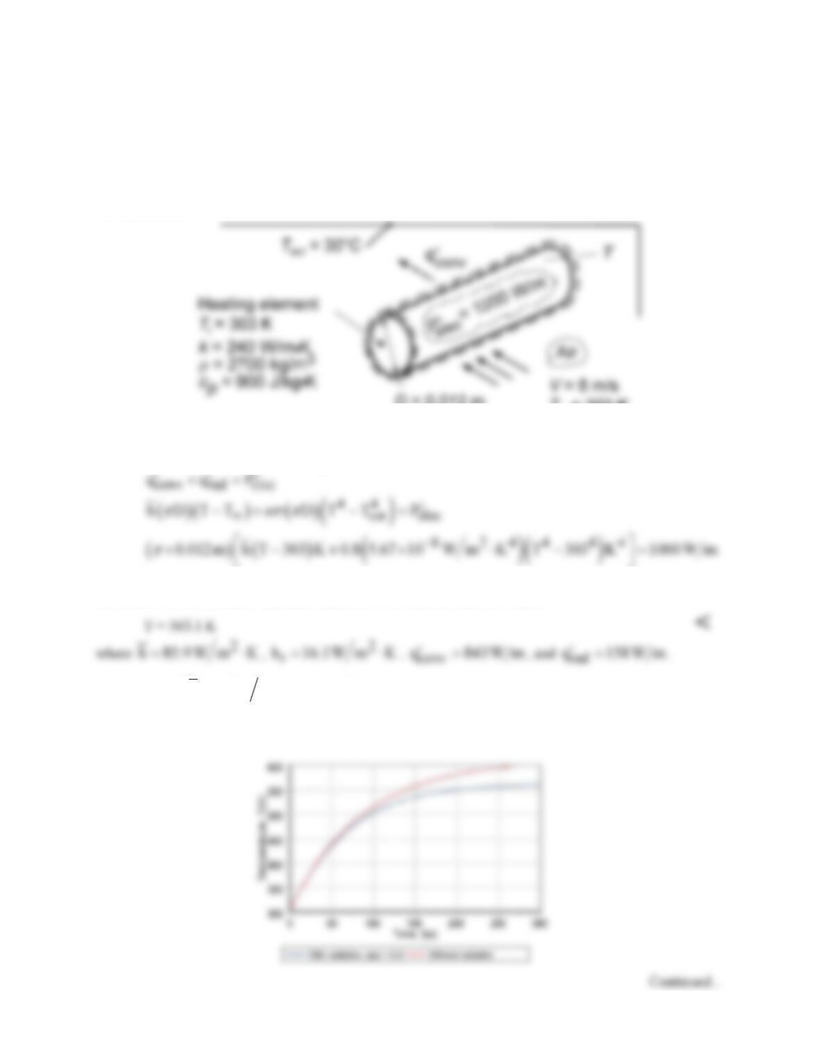
ANALYSIS: (a) Performing an energy balance for steady–state conditions, we obtain
Using the IHT Energy Balance Model for an Isothermal Solid Cylinder with the Correlations Tool Pad
for a Cylinder in Crossflow and the Properties Tool Pad for Air, we obtain
(b) With Bi =
( )
ro
hhrk+
= (102 W/m2⋅K)0.006 m/240 W/m⋅K = 0.0026, the transient behavior may
be analyzed using the lumped capacitance method. Using the IHT Lumped Capacitance Model to
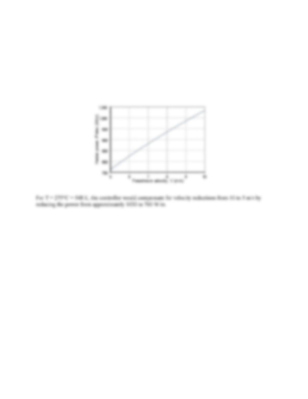
perform the numerical integration, the following temperature histories were obtained.
PROBLEM 7.37 (Cont.)
The agreement between predictions with and without radiation for t < 50s implies negligible radiation.
However, as the heater temperature increases with time, radiation becomes significant, yielding a reduced
heater temperature. Steady–state temperatures correspond to 563 K and 612 K, with and without
radiation, respectively. The time required for the heater to reach 553 K (with radiation) is t ≈ 215s. <
(c) If the heater temperature is to be maintained at a fixed value in the face of velocity excursions,
provision must be made for adjusting the heater power. Using the Explore and Graph options of IHT
with the model of part (a), the following results were obtained.
COMMENTS: Although convection heat transfer substantially exceeds radiation heat transfer, radiation
is not negligible and should be included in the analysis. If it is neglected, a steady–state temperature of T
= 612 K would be predicted for
elec
P′
= 1000 W/m, in contrast to 563 K from the results of part (a).
PROBLEM 7.38
KNOWN: Air at atmospheric pressure in cross flow over a cylinder. Cylinder diameter, length, and
temperature. Air velocity and temperature.
FIND: Heat transfer coefficient, convection thermal resistance, convection heat transfer rate. Plot
convection heat transfer coefficient and convection heat rate for 0.05 m ≤ D ≤ 0.5 m.
SCHEMATIC:
ASSUMPTIONS: (1) Steady–state incompressible flow conditions, (2) Constant properties, (3)
Negligible end effects.
PROPERTIES: Table A-4, Air, (T = 318 K):
ν
= 17.70 × 10⁻⁶ m2/s, k = 0.0276 W/m⋅K, Pr = 0.704.
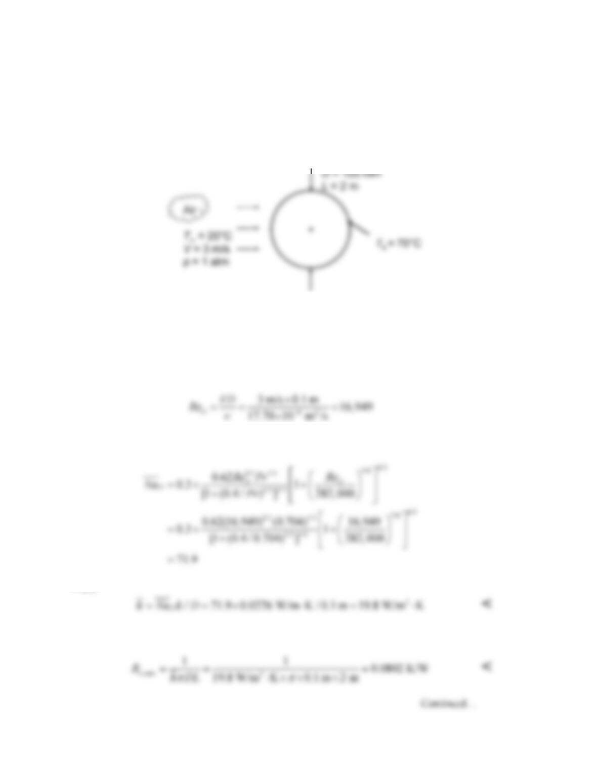
ANALYSIS: The Reynolds number is
Thus, ReDPr > 0.2, and the Churchhill-Bernstein correlation (Equation 7.54) can be used:
Thus,
The thermal resistance is
PROBLEM 7.38 (Cont.)
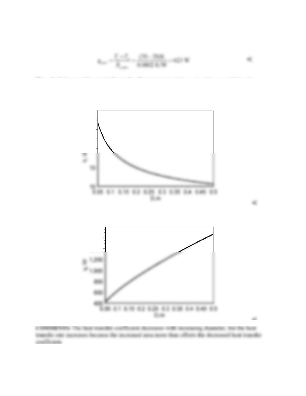
And the convection heat transfer rate is
The calculations can be repeated over the diameter range 0.05 m ≤ D ≤ 0.5 m to yield the plots
below. Note that ReDPr > 0.2 over this entire range, therefore the Churchhill-Bernstein correlation
is applicable.
Convection heat transfer coefficient
30
25
20
Heat transfer rate
1,800
1,600
1,400
<
PROBLEM 7.39
KNOWN: Long, thin metal plate hung vertically in air. Plate width, height, and initial temperature. Air
velocity and temperature.
FIND: Initial rate of heat loss if plate is parallel or perpendicular to flow, accounting for both plate
surfaces. Which orientation maximizes heat loss?
SCHEMATIC:
ASSUMPTIONS: (1) Steady–state incompressible flow conditions, (2) Constant properties, (3)
Negligible radiation effects.
PROPERTIES: Table A-4, Air, (T = 448 K):
ν
= 32.15 × 10⁻⁶ m2/s, k = 0.0372 W/m⋅K, Pr = 0.686.
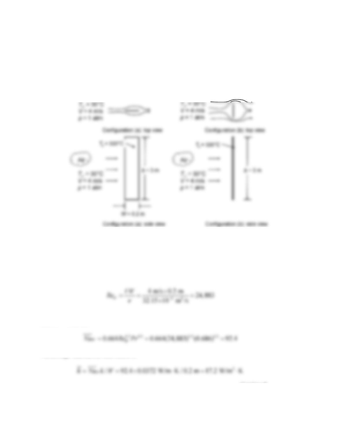
ANALYSIS: For flow parallel to the plate, we calculate the Reynolds number based on the plate
dimension in the flow direction, W:
The flow is laminar since ReW < 5 × 10⁵. The average Nusselt number is given by Equation 7.30 (valid
since Pr > 0.6), thus
The average heat transfer coefficient is
Continued…
PROBLEM 7.39 (Cont.)
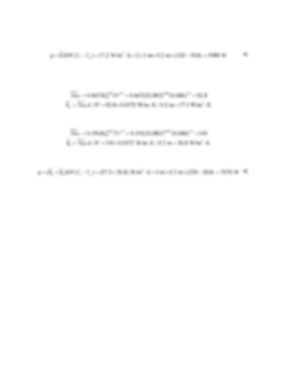
Thus the heat transfer rate from both surfaces of the plate is
When the flow is perpendicular to the plate, Equation 7.52 may be used with the coefficients found in
Table 7.3 for a thin plate perpendicular to the flow. The Reynolds number is again based on the
dimension W. For the front surface,
And for the back surface,
The heat transfer rate from both sides of the plate is
The heat loss is greater for the perpendicular orientation. <
COMMENTS: The radiation heat transfer rate can be estimated by assuming that the surroundings are at
30°C and the emissivity is unity. The result is 7840 W, which is not negligible, however if the plate is
polished the emissivity would be less and the radiation heat transfer could be negligible.
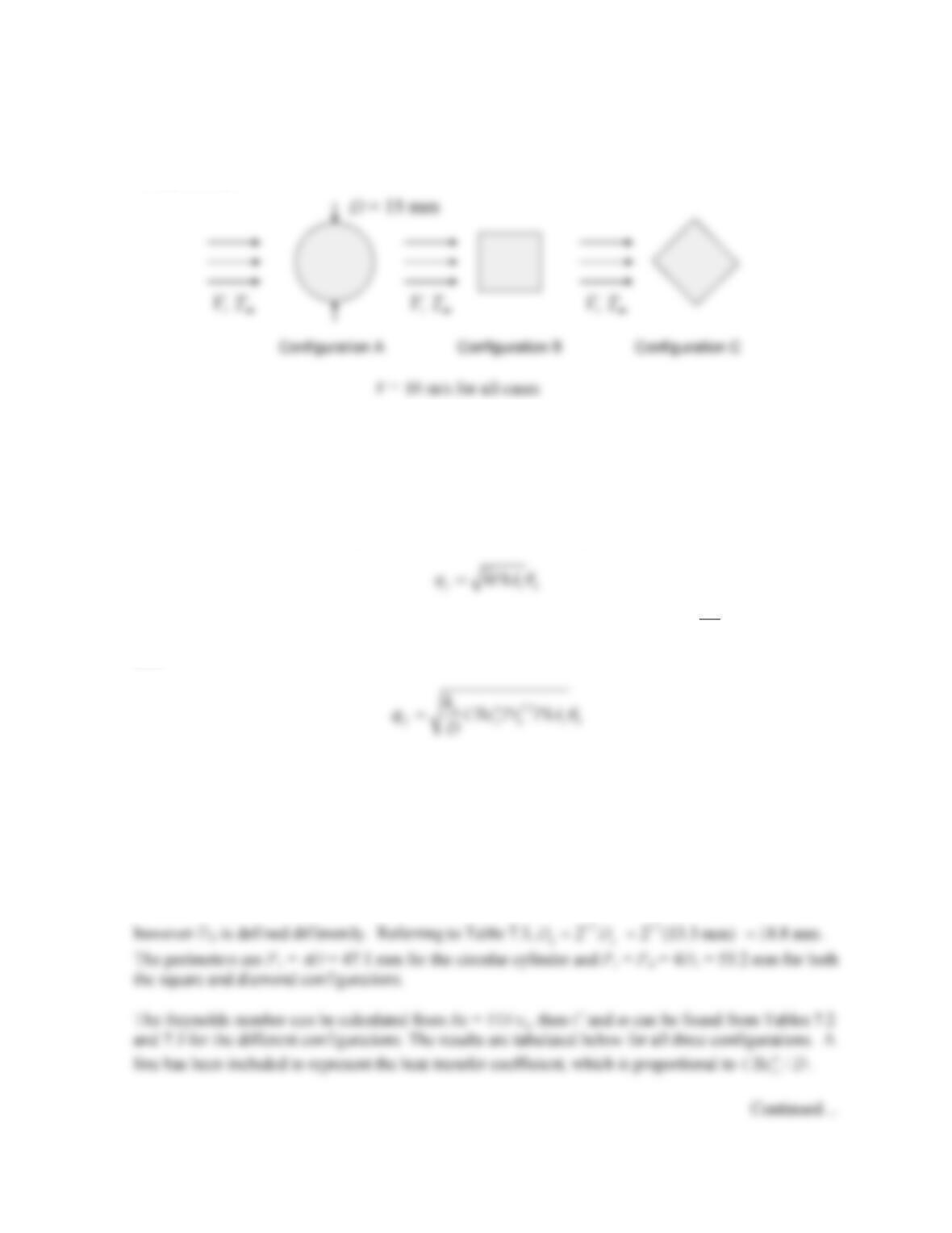
PROBLEM 7.40
KNOWN: Geometry and dimensions of three pin fins. Velocity and temperature of air in cross flow.
FIND: Which fin has the largest heat transfer rate.
SCHEMATIC:
ASSUMPTIONS: (1) Steady–state, (2) Constant properties, (3) Fins can be treated as infinitely long,
(4) Presence of fin base doesn’t affect heat transfer coefficients.
PROPERTIES: Table A-4 Air (T = 350 K):
ν
a = 20.92 × 10⁻⁶ m2/s
ANALYSIS: For infinitely long fins, the fin heat transfer rate is given by Equation 3.85:
In every case, the heat transfer coefficient is found from a correlation of the form,
1/3m
D
D
Nu CRe Pr=
,
thus
where subscript a refers to air properties. Since each fin has the same cross–sectional area, the
parameters that vary from one configuration to another are D, C, ReD, m, and P. Thus, it is sufficient
to examine the combination parameter
/
m
D
CRe P D
to determine which fin has the largest heat transfer
rate.
The cross-sectional area of the circular cylinder is Ac =
π
D2/4. Thus the dimension of the square, Ds,
is
1/2 1/ 2 1/2
/ 2 (15 mm) / 2 13.3 mm
sc
DA D
ππ
= = = =
. The dimension of the diamond is the same,

PROBLEM 7.40 (Cont.)
Configuration A
(circular)
Configuration B
(square)
Configuration C
(diamond)
D (mm)
15
13.3
18.8
For fins of equal mass, the square fin configuration has the largest heat transfer rate. <
COMMENTS: (1) For the same cross–sectional area, the square and diamond configurations have
larger perimeters than the circular cylinder, which contributes to the larger heat transfer rate. (2) For
the same cross–sectional area, the square and diamond configurations have larger heat transfer
coefficients, which also contributes to the larger heat transfer rates.
P (mm)
47.1
53.2
53.2
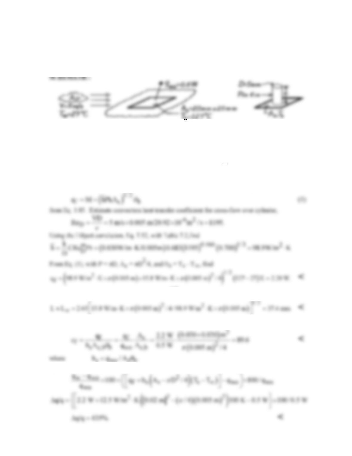
PROBLEM 7.41
KNOWN: Pin fin installed on a surface with prescribed heat rate and temperature.
FIND: (a) Maximum heat removal rate possible, (b) Length of the fin, (c) Effectiveness, εf, (d)
Percentage increase in heat rate from surface due to fin.
ASSUMPTIONS: (1) Steady-state conditions, (2) Conditions over As are uniform for both
situations, (3) Conditions over fin length are uniform, (4) Flow over pin fin approximates cross-flow.
PROPERTIES: Table A-4, Air (Tf = (T∞ + Ts)/2 = (27 + 127)°C/2 = 350 K): ν = 20.92 × 10⁻⁶
m2/s, k = 30.0 × 10⁻³ W/m⋅K, Pr = 0.700. Table A-1, SS AISI304 (
T
= Tf = 350 K): k = 15.8
W/m⋅K.
ANALYSIS: (a) Maximum heat rate from fin occurs when fin is infinitely long,
(b) From Example 3.9, L ≈ L∞ = 2.65(kAc/hP)1/2. Hence,
(c) From Eq. 3.86, with hs used for the base area As, the effectiveness is
s wo s b
(d) The percentage increase in heat rate with the installed fin (w) is
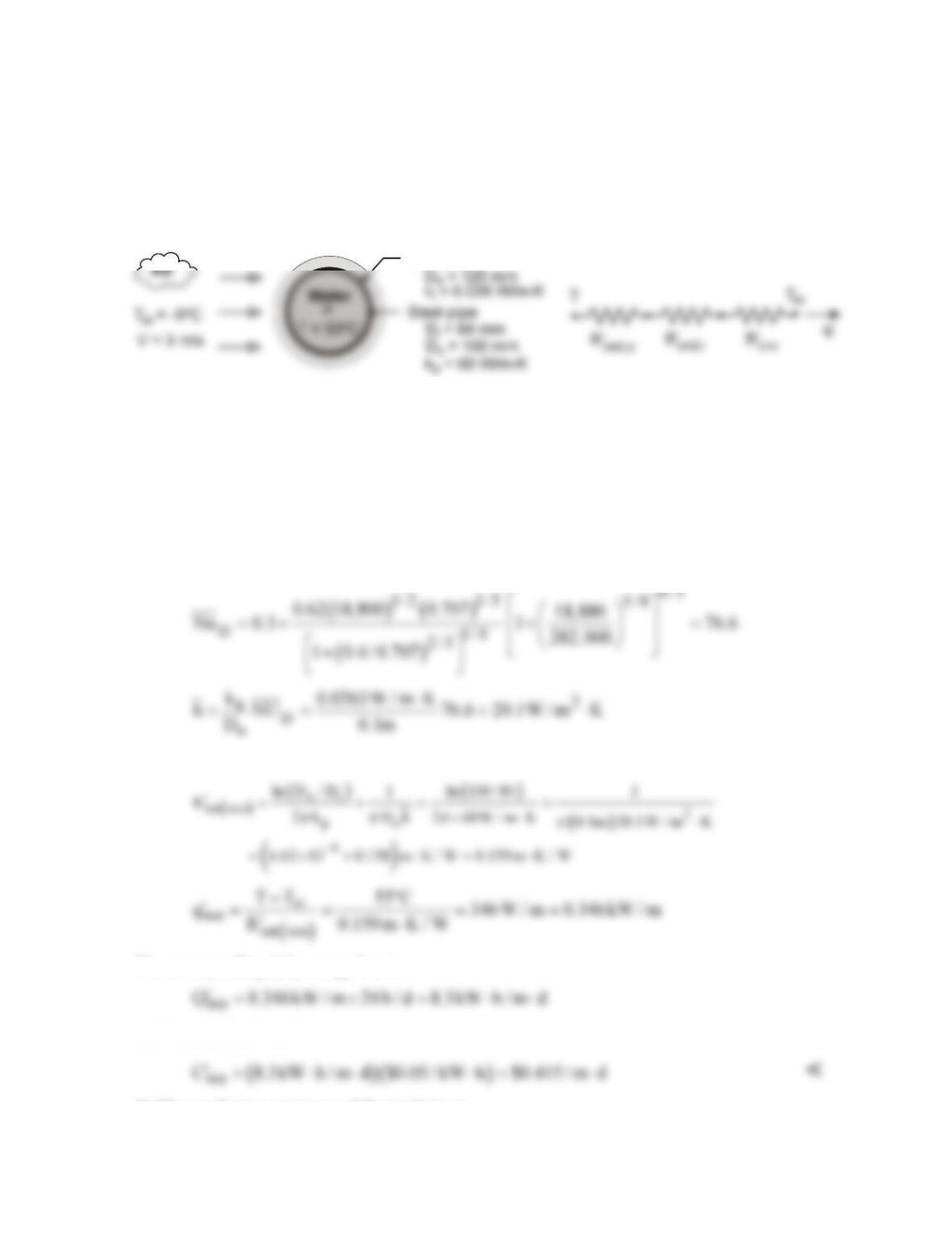
PROBLEM 7.42
KNOWN: Diameter, thickness and thermal conductivity of steel pipe. Temperature of water flow in
pipe. Temperature and velocity of air in cross flow over pipe. Cost of producing hot water.
FIND: (a) Cost of daily heat loss from an uninsulated pipe, (b) Savings associated with insulating the
pipe.
SCHEMATIC:
Insulation
ASSUMPTIONS: (1) Steady-state, (2) Negligible convection resistance for water flow, (3)
Negligible contact resistance between insulation and pipe, (4) Negligible radiation.
PROPERTIES: Table A-4, air
( )
,
fa
p 1atm, T 300K : k 0.0263 W / m K=≈= ⋅
62
15.89 10 m / s, Pr 0.707.
ν
−
=×=
ANALYSIS: (a) With
62
Do
Re VD / 3 m / s 0.1m /15.89 10 m / s 18, 880,
ν
−
==× ×=
application of the
Churchill-Bernstein correlation yields
Without the insulation, the total thermal resistance and heat loss per length of pipe are then
The corresponding daily energy loss is
and the associated cost is
(b) The conduction resistance of the insulation is
Continued …
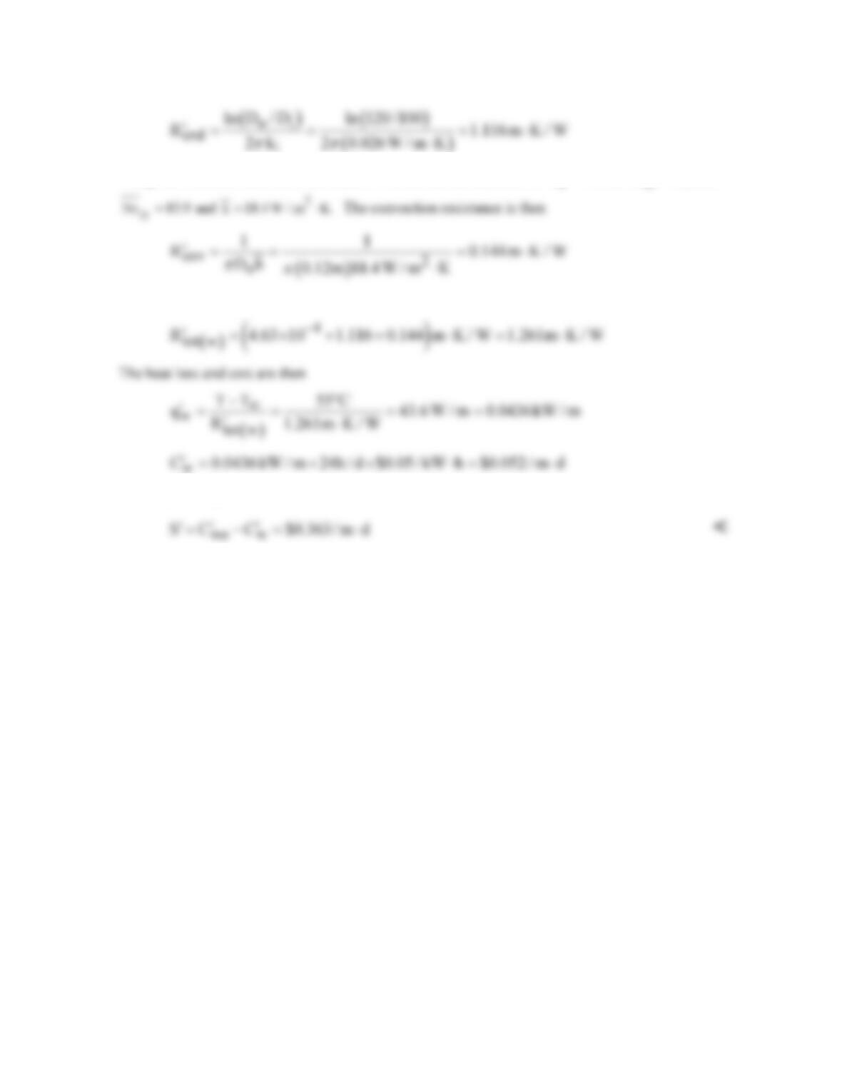
PROBLEM 7.42 (Cont.)
Using the Churchill-Bernstein correlation with an outside diameter of
o
D 0.12m,=
D
Re 22, 660,=
and the total resistance is
The daily savings is then
COMMENTS: (1) The savings are significant, and the pipe should be insulated. (2) Assuming a
negligible temperature drop across the pipe wall, a pipe emissivity of εp = 0.6 and surroundings at
sur
T 268K,=
the radiation coefficient associated with the uninsulated pipe is
( )
r sur
h TT
εs
= +
( )
( )
2 2 8 24
sur
T T 0.6 5.67 10 W / m K 591K
−
+ =×× ⋅
( )
2 22 2
323 268 K 3.5 W / m K.+= ⋅
Accordingly,
radiation increases the heat loss estimate of Part (a) by approximately 17%.
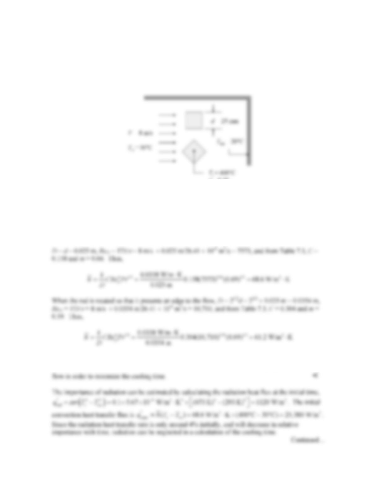
PROBLEM 7.43
KNOWN: Dimension and initial temperature of long aluminum rods of square cross-section.
Velocity and temperature of air in cross flow. Rod emissivity and surroundings temperature.
FIND: Which orientation of the rod relative to the cross flow should be used to minimize the time
needed for the rods to reach a temperature of 60°C. Required cooling time for preferred configuration.
SCHEMATIC:
ε
= 0.10
ASSUMPTIONS: (1) Constant properties.
PROPERTIES: Table A-4, Air (T = 400 K):
ν
= 26.41 × 10⁻⁶ m2/s, k = 0.0338 W/m⋅K, Pr = 0.690.
Table A-1, Pure aluminum (T = 500 K):
ρ
s = 2702 kg/m3, cp,s = 991 J/kg⋅K, ks = 235 W/m⋅K.
ANALYSIS: The heat transfer coefficient can be calculated from Equation 7.52, with the dimension
D defined differently for the two configurations, as shown in Table 7.3. When the air flows
perpendicular to a face of the rod,
Radiation will affect both rods in the same way, therefore the rod with the larger value of convection
heat transfer coefficient will cool faster. The rod should be oriented with a face perpendicular to the

PROBLEM 7.43 (Cont.)
The cooling process can be modeled using the lumped capacitance approximation, provided the Biot
number is small. Using a characteristic length of L = V/As = d/4 = 0.00625 m, the Biot number is
Therefore, the lumped capacitance approximation is valid and the cooling time is given by Equation
5.5,
3
2
2702 kg/m 0.025 m 991 J/kg K 400 30
ln ln ln 613 s
4 4 68.6 W/m K 60 30
ii
s
TT
Vc dc
thA h T T
θ
ρρ
θ
∞
∞
−××⋅ −
= = = =
− ×⋅ −
<
COMMENTS: IHT was used to solve this problem including the effect of radiation. The required
cooling time, including radiation, is 601 s. Inclusion of radiation has a minor effect on the cooling
time, as expected.
.
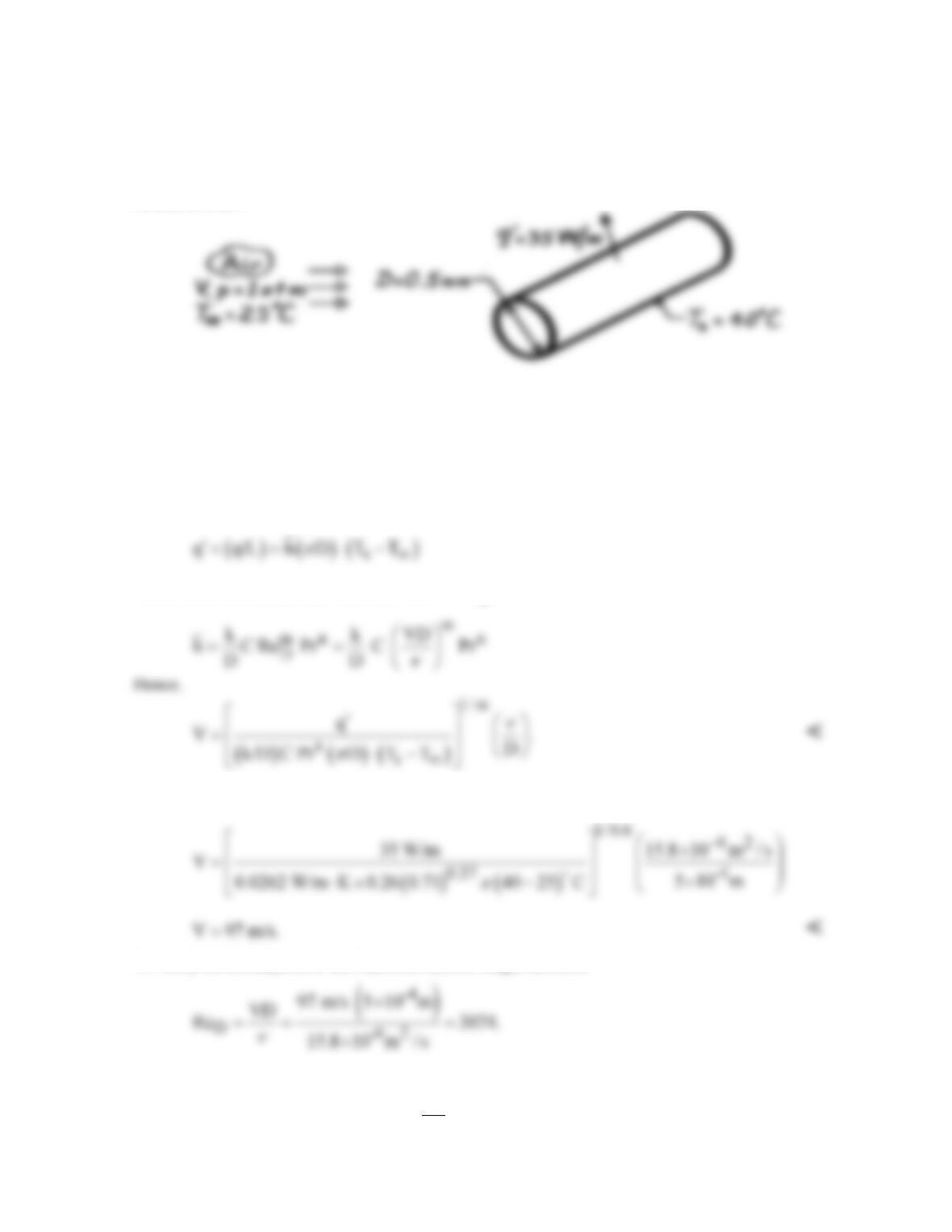
PROBLEM 7.44
KNOWN: Temperature and heat dissipation in a wire of diameter D.
FIND: (a) Expression for flow velocity over wire, (b) Velocity of airstream for prescribed
conditions.
SCHEMATIC:
ASSUMPTIONS: (1) Steady-state conditions, (2) Uniform wire temperature, (3) Negligible
radiation.
PROPERTIES: Table A-4, Air (T∞ = 298 K, 1 atm): ν = 15.8 × 10⁻⁶ m2/s, k = 0.0262 W/m⋅K, Pr =
0.71; (Ts = 313 K, 1 atm): Pr = 0.705.
ANALYSIS: (a) The rate of heat transfer per unit cylinder length is
where, from the Zhukauskas relation, with Pr ≈ Prs,
(b) Assuming (103 < ReD < 2 × 10⁵), C = 0.26, m = 0.6 from Table 7.4. Hence,
To verify the assumption of the Reynolds number range, calculate
Hence the assumption was correct.
COMMENTS: The major uncertainty associated with using this method to determine V is that
associated with use of the correlation for
D
Nu .
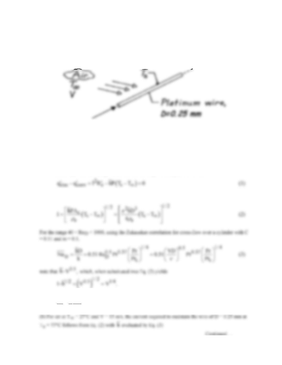
PROBLEM 7.45
KNOWN: Platinum wire maintained at a constant temperature in an airstream to be used for
determining air velocity changes.
FIND: (a) Relationship between fractional changes in current to maintain constant wire temperature
and fractional changes in air velocity and (b) Current required when air velocity is 15 m/s.
SCHEMATIC:
ASSUMPTIONS: (1) Steady-state conditions, (2) Cross-flow of air on wire with 40 < ReD < 1000,
(3) Radiation effects negligible, (4) Wire is isothermal.
PROPERTIES: Platinum wire (given): Electrical resistivity, ρe = 17.1 × 10⁻⁵ Ohm⋅m; Table A-4,
Air (T∞ = 27°C = 300 K, 1 atm): ν = 15.89 × 10⁻⁶ m2/s, k = 0.0263 W/m⋅K, Pr = 0.707; (Ts = 77°C
= 350 K, 1 atm): Prs = 0.700.
ANALYSIS: (a) From an energy balance on a unit length of the platinum wire,
where the electrical resistance per unit length is
e ec
R /A ,
ρ
′=
P = πD, and Ac = πD2/4. Hence,
Differentiating the proportionality and dividing the result by the proportionality, it follows that
I 1V
.
I 4V
∆∆
≈
(4) <
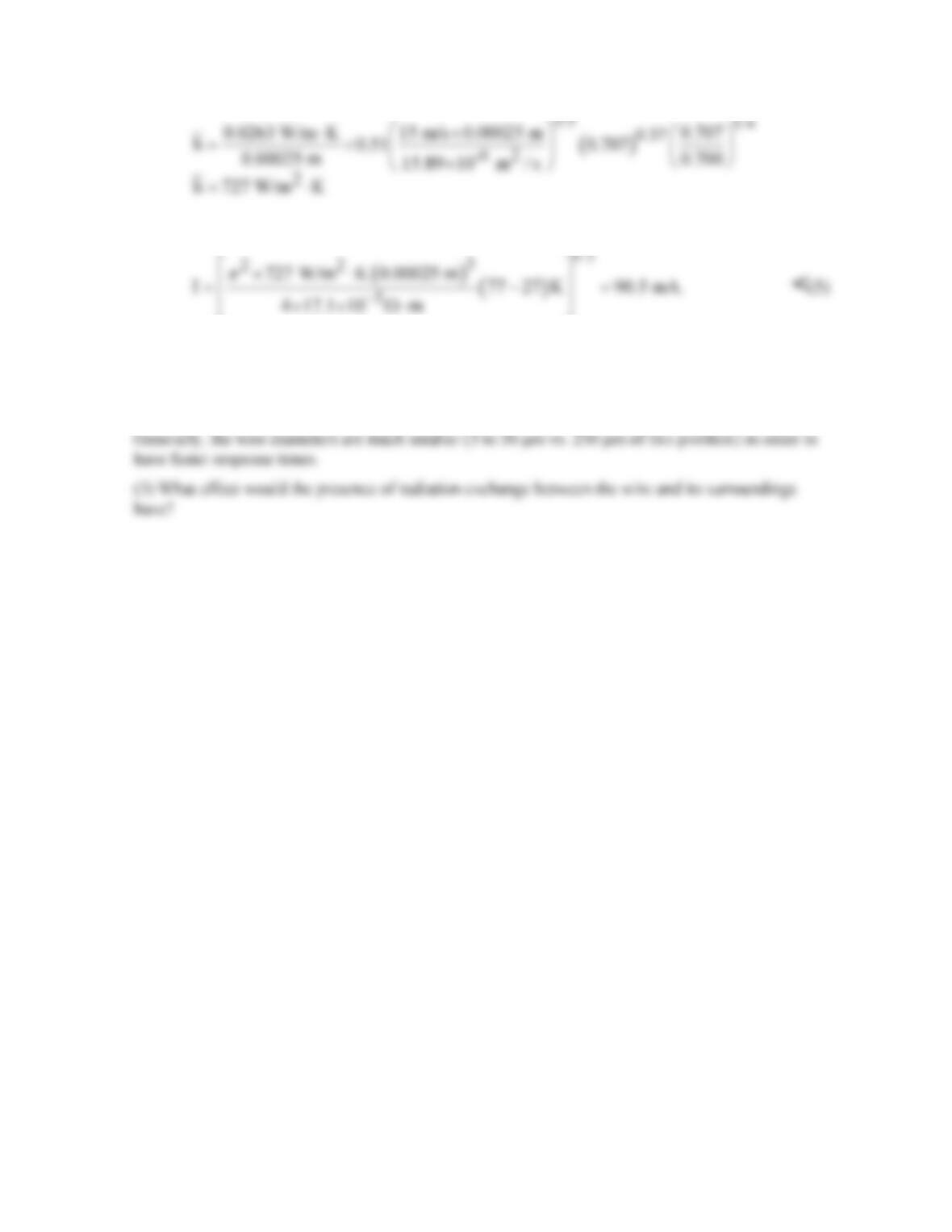
PROBLEM 7.45 (Cont.)
where ReD = 236. Hence the required current is
COMMENTS: (1) To measure 1% fractional velocity change, a 0.25% fractional change in current
must be measured according to Eq. (4). From Eq. (5), this implies that ∆I = 0.0025I = 0.0025 × 90.5
mA = 226 µA. An electronic circuit with such measurement sensitivity requires care in its design.
(2) Instruments built on this principle to measure air velocities are called hot-wire anemometers.
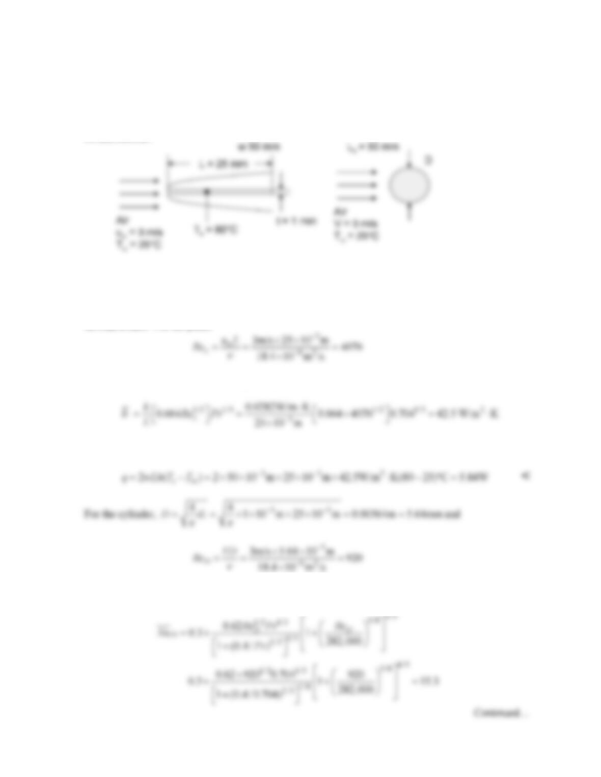
PROBLEM 7.46
KNOWN: Dimensions of a flat plate in parallel flow. Plate and air temperatures and air velocity.
Dimensions of a horizontal cylinder.
FIND: Convective heat loss rate from top and bottom of the flat plate and from the cylinder.
SCHEMATIC:
ASSUMPTIONS: (1) Steady–state conditions, (2) Constant properties.
PROPERTIES: Table A.4, air (Tf = (80°C + 25°C)/2 = 52.5°C ≈ 325K, p = 1 atm):
ν
= 18.4×10⁻⁶
m2/s, Pr = 0.704, k = 0.0282 W/m⋅K.
ANALYSIS: For the plate,
Therefore, the flow is laminar and Eq. 7.30 yields
and the convective heat transfer rate from the top and bottom of the flat plate is
Equation 7.54 yields