PROBLEM 7.68
KNOWN: Conditions associated with Example 7.7, but with reduced longitudinal and transverse
pitches.
FIND: (a) Air side convection coefficient, (b) Tube bundle pressure drop, (c) Heat rate.
SCHEMATIC:
ASSUMPTIONS: (1) Steady-state conditions, (2) Uniform tube surface temperature, (3) Negligible
radiation and incompressible flow.
PROPERTIES: Table A-4, Atmospheric air (T∞ = 288 K): ρ = 1.217 kg/m3, ν = 14.82 × 10⁻⁶ m2/s,
k = 0.0253 W/m⋅K, Pr = 0.71, cp = 100.7 J/kg⋅K; (Ts = 343 K): Pr = 0.701.
ANALYSIS: (a) From the tube pitches, find
Hence, the maximum velocity occurs on the transverse plane, and
and (ST/SL) = 1 < 2, it follows from Table 7.5 that
1
C 0.35 m 0.60.= =
Hence, from the Zukauskas correlation and Table 7.6 (C2 = 0.95),
(b) From the Zukauskas relation
PROBLEM 7.68 (Cont.)
Hence
( )
2
32
1.217 kg/m 30 m/s
p 7 1.02 0.38 1490 N/m
2
D=× =
p 0.0149D=
bar. <
(c) The air outlet temperature is obtained from
The log mean temperature difference is
COMMENTS: Making the tube bank more compact has the desired effect of increasing the
convection coefficient and therefore the heat transfer rate. However, it has the adverse effect of
increasing the pressure drop and hence the fan power requirement. Note that the convection
coefficient increases by a factor of (234/135.6) = 1.73, while the pressure drop increases by a factor of
h
PROBLEM 7.69
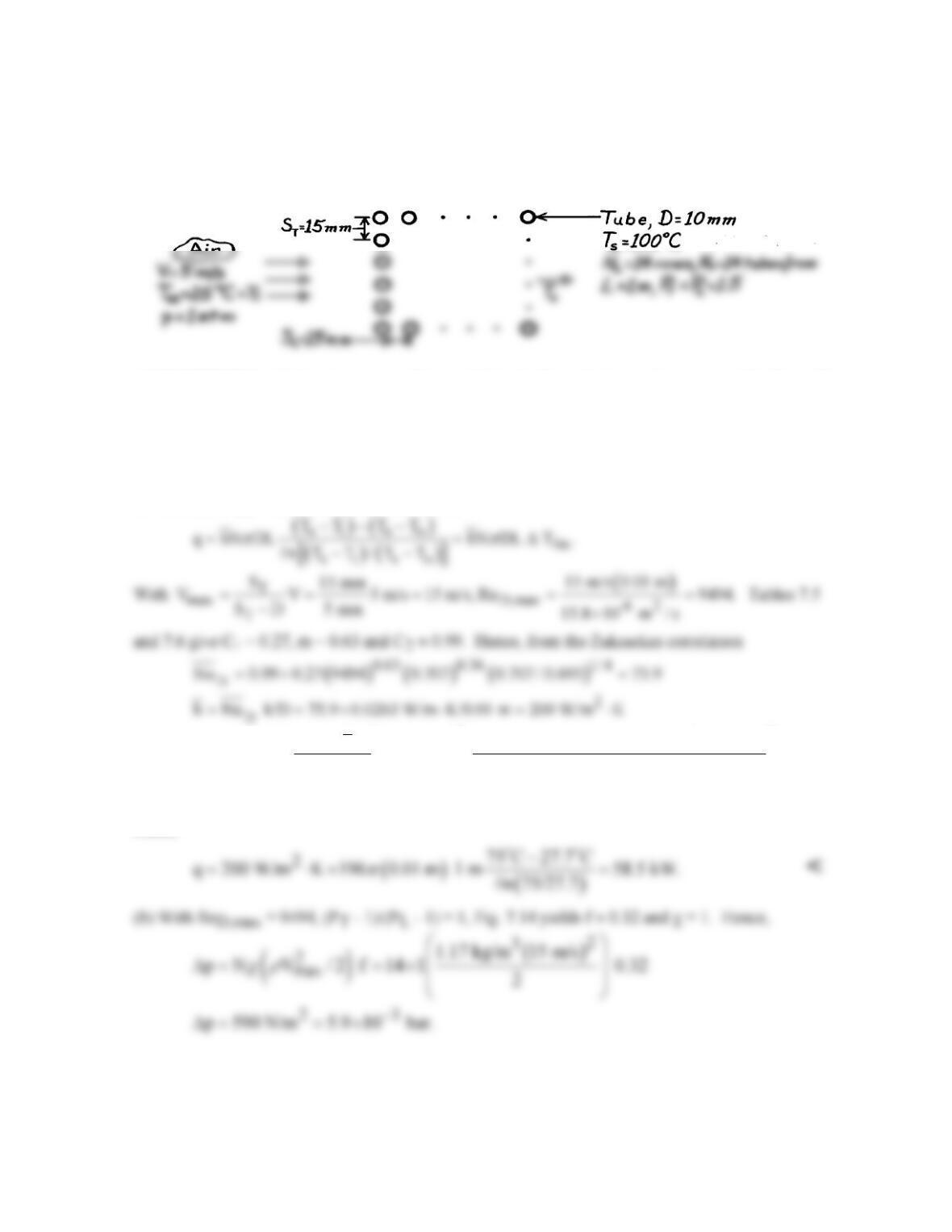
KNOWN: Surface temperature and geometry of a tube bank. Velocity and temperature of air in
cross flow.
FIND: (a) Total heat transfer, (b) Air flow pressure drop.
SCHEMATIC:
ASSUMPTIONS: (1) Steady-state conditions, (2) Negligible radiation and incompressible flow, (3)
Uniform surface temperature.
PROPERTIES: Table A-4, Atmospheric air (T∞ = 298 K): ν = 15.8 × 10⁻⁶ m2/s, k = 0.0263
W/m⋅K, Pr = 0.707, cp = 1007 J/kg⋅K, ρ = 1.17 kg/m3; (Ts = 373 K): Pr = 0.695.
ANALYSIS: (a) The total heat transfer rate is
( )
2
so si 3
TTp
DNh 0.01 m 196 200 W/m K
T T T T exp 75 C exp
VN S c 1.17 kg/m 5 m/s 14 0.015 m 1007 J/kg K
ππ
ρ
× ×× ⋅
−= − − = − × ×× × ⋅
a
so
T T 27.7 C.−=
a
Hence
COMMENTS: The heat transfer rate would have been substantially overestimated (93.3 kW) if the
inlet temperature difference (Ts – Ti) had been used in lieu of the log-mean temperature difference.
PROBLEM 7.70
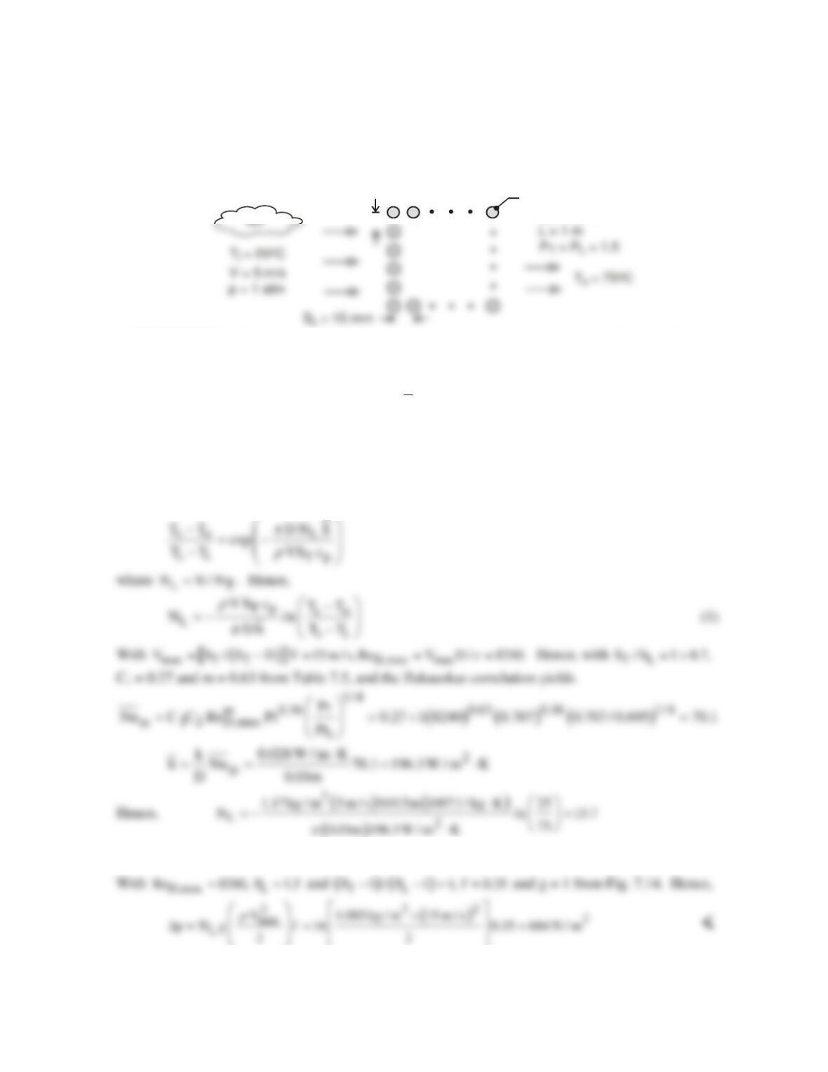
KNOWN: Surface temperature and geometry of a tube bank. Inlet velocity and inlet and outlet
temperatures of air in cross flow over the tubes.
FIND: Number of tube rows needed to achieve the prescribed outlet temperature and corresponding
pressure of drop of air.
SCHEMATIC:
Tube, D = 10 mm
TC
s o
= 100
S
T
= 15 mm
ASSUMPTIONS: (1) Steady-state, (2) Negligible temperature drop across tube wall and uniform
outer surface temperature, (3) Constant properties, (4) C2 ≈ 1, (5) Negligible radiation and
incompressible flow.
PROPERTIES: Table A-4, Atmospheric air.
( )
( )
3
io
T T T / 2 323K : 1.085 kg / m ,
ρ
=+= =
p
c 1007 J / kg K,= ⋅
62
18.2 10 m / s, k 0.028 W / m K, Pr 0.707;
ν
−
=× = ⋅=
( )
i
T 298K :=
3
1.17 kg / m ;
ρ
=
( )
ss
T 373K : Pr 0.695.= =
ANALYSIS: The temperature difference
( )
s
TT−
decreases exponentially in the flow direction, and
at the outlet
and 16 tube rows should be used
L
N 16=
<
COMMENTS: (1) With C2 = 0.99 for NL = 16 from Table 7.6, assumption 4 is appropriate. (2)
Note use of the density evaluated at Ti = 298K in Eq. (1).
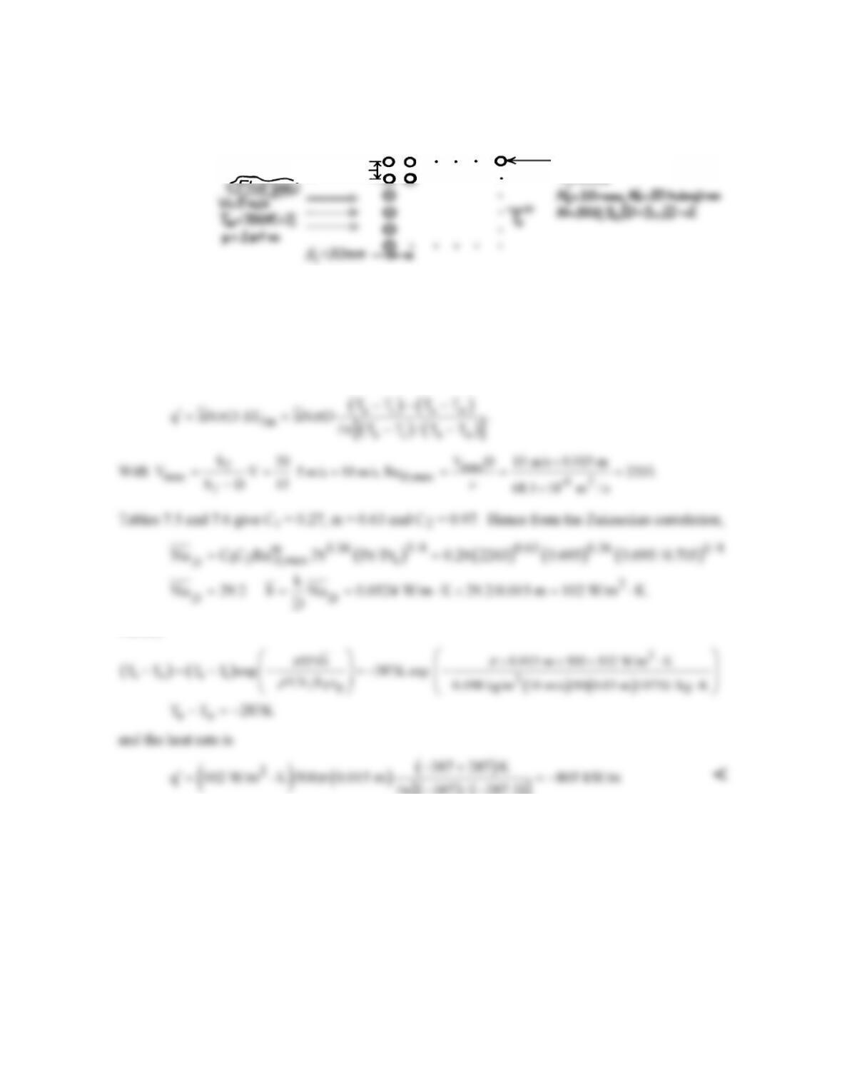
PROBLEM 7.71
KNOWN: Geometry, surface temperature, and air flow conditions associated with a tube bank.
FIND: Rate of heat transfer per unit length.
SCHEMATIC:
ASSUMPTIONS: (1) Steady-state conditions, (2) Negligible radiation effects and incompressible
flow, (3) Gas properties are approximately those of air.
PROPERTIES: Table A-4, Air (313K, 1 atm): Pr = 0.705; Table A-4, Air (700K, 1 atm): ν = 68.1
× 10-6 m2/s, k = 0.0524 W/m⋅K, Pr = 0.695, ρ = 0.498 kg/m3, cp = 1075 J/kg⋅K.
ANALYSIS: The rate of heat transfer per unit length of tubes is
Hence,
( ) ( )
[ ]
n 387 / 287.3
−−
COMMENTS: (1) There is a significant decrease in the gas temperature as it passes through the tube
bank. Hence, the heat rate would have been overestimated (- 931 kW) if the inlet temperature
difference had been used in lieu of the log-mean temperature difference. (2) The negative sign
implies heat transfer to the water. (3) If the temperature of the water increases substantially, the
assumption of uniform Ts becomes poor. The extent to which the water temperature increases
depends on the water flow rate.
S
T
=30mm Tube,D=15mm
T
=313K
PROBLEM 7.72
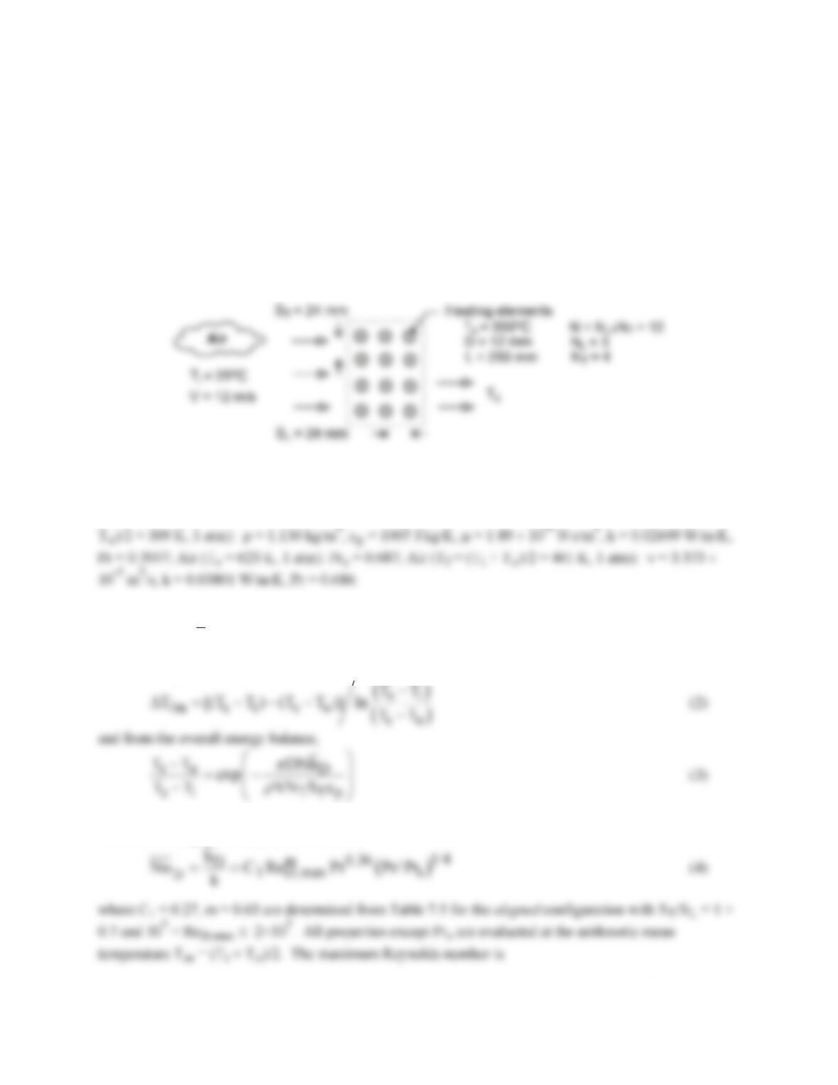
KNOWN: An air duct heater consists of an aligned arrangement of electrical heating elements with SL =
ST = 24 mm, NL = 3 and NT = 4. Atmospheric air with an upstream velocity of 12 m/s and temperature of
25°C moves in cross flow over the elements with a diameter of 12 mm and length of 250 mm maintained
at a surface temperature of 350°C.
FIND: (a) The total rate of heat transfer to the air and the temperature of the air leaving the duct heater,
(b) The pressure drop across the element bank and the fan power requirement, (c) Compare the average
convection coefficient obtained in part (a) with the value for an isolated (single) element; explain the
relative difference between the results; (d) What effect would increasing the longitudinal and transverse
pitches to 30 mm have on the exit temperature of the air, the total heat rate, and the pressure drop?
SCHEMATIC:
ASSUMPTIONS: (1) Steady–state conditions, (2) Negligible radiation effects, (3) Negligible effect of
change in air temperature across tube bank on air properties.
PROPERTIES: Table A-4, Air (Ti = 298, 1 atm ): ρ = 1.171 kg/m3, cp = 1007 J/kg⋅K; Air (Tm = (Ti +
ANALYSIS: (a) The total rate of heat transfer to the air is determined from the rate equation
( )
Dm
q N h DL T
π
= D
(1)
where the log mean temperature difference is
The properties ρ and cp in Eq. (3) are evaluated at the inlet temperature Ti. The average convection
coefficient using the Zukauskus correlation,
Continued …
PROBLEM 7.72 (Cont.)
D,max max
Re V D /
ρm
=
(5)
where for the aligned arrangement, the maximum velocity occurs at the transverse plane
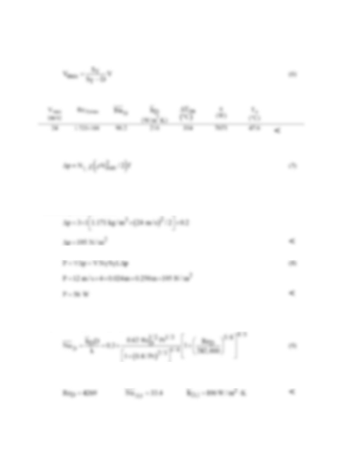
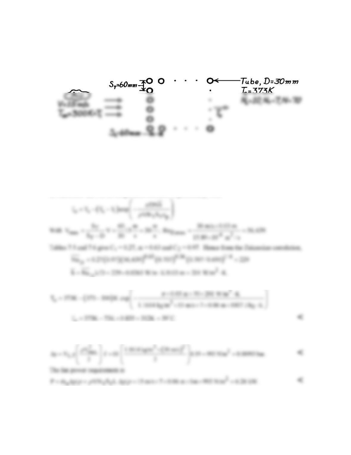
The results of the analyses for ST = SL = 24 mm are tabulated below.
(b) The pressure drop across the tube bundle is
where the friction factor, f, and correction factor, χ, are determined from Fig. 7.14 using ReD,max = 1.723
× 104,
f = 0.2 χ = 1
Substituting numerical values,
The fan power requirement is
where ∀ is the volumetric flow rate. For this calculation, ρ in Eq. (7) was evaluated at Tm.
(c) For a single element in cross flow, the average convection coefficient can be estimated using the
Churchill-Bernstein correlation,
where all properties are evaluated at the film temperature, Tf = (Ti + To)/2. The results of the
calculations are
Continued …
PROBLEM 7.72 (Cont.)
For the isolated element,
2
D,1
h 106 W / m K,= ⋅
compared to the average value for the array,
2
D
h 216 W / m K.= ⋅
Because the first row of the array acts as a turbulence grid, the heat transfer
coefficient for the second and third rows will be larger than for the first row. Here, the array value is
twice that for the isolated element.
(d) The effect of increasing the longitudinal and transverse pitches to 30 mm, should be to reduce the
outlet temperature, heat rate, and pressure drop. The effect can be explained by recognizing that the
maximum Reynolds number will be decreased, which in turn will result in lower values for the
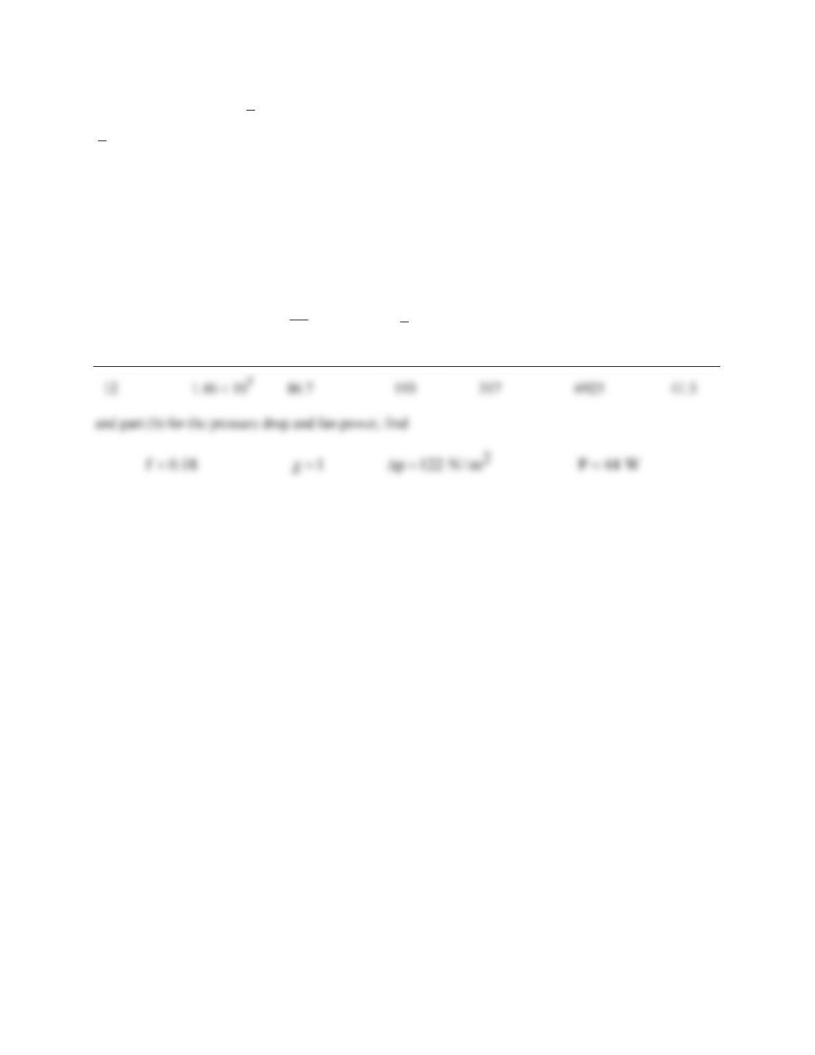
convection coefficient and pressure drop. Repeating the calculations of part (a) for SL = ST = 30 mm,
find
Vmax ReD,max
D
Nu
D
h
m
TD
q To
(m/s) (W/m2⋅K) (°C) (W) (°C)
PROBLEM 7.73
KNOWN: Surface temperature and geometry of a tube bank. Velocity and temperature of air in
cross–flow.
FIND: (a) Air outlet temperature, (b) Pressure drop and fan power requirements.
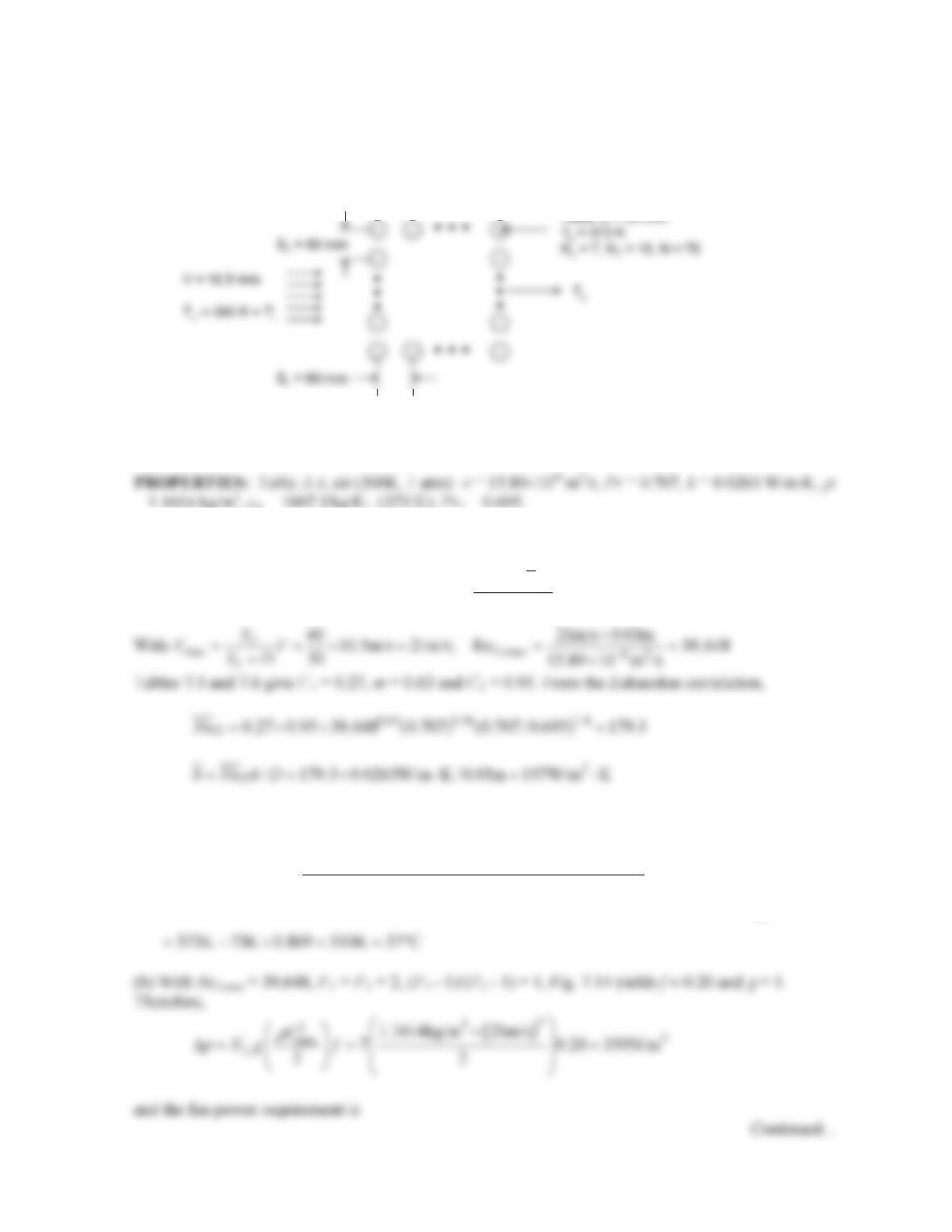
SCHEMATIC:
ASSUMPTIONS: (1) Steady-state conditions, (2) Negligible radiation, (3) Air pressure is
approximately one atmosphere, (4) Uniform surface temperature.
PROPERTIES: Table A-4, Air (300 K, 1 atm): ρ = 1.1614 kg/m3, cp = 1007 J/kg⋅K, ν = 15.89 ×
10-6 m2/s, k = 0.0263 W/m⋅K, Pr = 0.707; (373K): Pr = 0.695.
ANALYSIS: (a) The air temperature increases exponentially, with
D
Hence,
o
(b) With ReD,max = 5.66 × 10⁴, PL = 2, (PT – 1)/(PL – 1) = 1, Fig. 7.14 yields f ≈ 0.19 and χ = 1.
Hence,
COMMENTS: The heat rate is
( ) ( )
apo i TT po i
qmcT T VNSL cT T
ρ
= −= −
( )
3
q 1.1614 kg/m 15 m/s 7 0.06m 1m 1007 J/kg K 312 300 K 88.4 kW.= × ×× × × ⋅ − =
PROBLEM 7.74
KNOWN: Surface temperature and geometry of tube bank. Velocity and temperature of air in cross-
flow.
FIND: (a) Air outlet temperature, (b) Pressure drop and fan power requirements.
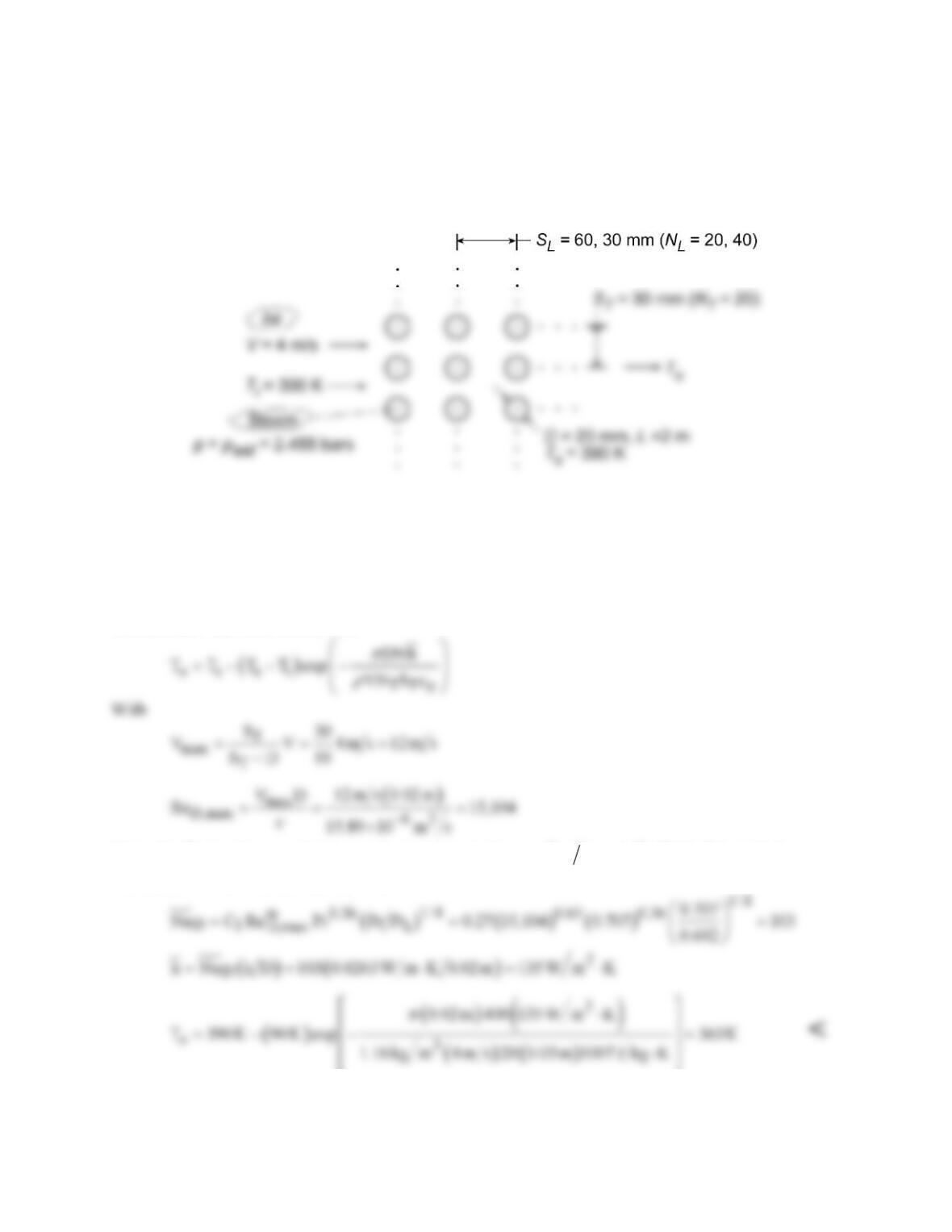
SCHEMATIC:
ASSUMPTIONS: (1) Steady–state conditions, (2) Negligible radiation, (3) Air pressure
approximately one atmosphere, (4) Uniform surface temperature.
= 1.1614 kg/m3, cp = 1007 J/kg∙K; (373 K): Prs = 0.695.
ANALYSIS: (a) The outlet air temperature may be found from
( )exp
o s si
TTp
DNh
T T TT VN S c
π
ρ
=−− −
and therefore,
2
3
0.03m 70 157W/m K
373K 73K exp 1.1614kg/m 10.5m/s 10 0.06m 1007J/kg K
o
T
π
× ×× ⋅
=−−
× ×× × ⋅
<

PROBLEM 7.74 (Cont.)
COMMENTS: Note that the mass flow rate here is the same as in Problem 7.73. In Problem 7.73,
for NL = 7 and NT = 10, the outlet temperature, pressure drop, and fan power requirements are To =
39°C, Dp = 993 N/m2, and P = 6.26 kW, respectively. Placing the tube bundle with fewer tubes in the
streamwise direction (NL/NT < 1) results in a higher overall heat transfer rate (lower air outlet
temperature) since the downstream tubes experience a larger temperature difference between the tube
wall and the flowing air. In addition, a significantly lower pressure drop and pumping power is
needed. However, the cross–sectional area of the duct within which the tube bundle is placed must be
increased, and therefore capital cost of installation would be higher, for the NL/NT < 1 case.
PROBLEM 7.75
KNOWN: Tube geometry and flow conditions for steam condenser. Surface temperature and pressure
of saturated steam.
FIND: (a) Coolant outlet temperature, (b) Heat and condensation rates, (c) Effects of reducing
longitudinal pitch and change in velocity.
SCHEMATIC:
ASSUMPTIONS: (1) Steady-state, (2) Negligible radiation, (3) Negligible effect of temperature change
on air properties, (parts a and b), (4) Applicability of convection correlation outside designated range.
PROPERTIES: Table A.4, air (Ti = 300 K): ρ = 1.16 kg/m3, cp = 1007 J/kg⋅K, ν = 15.89 × 10⁻⁶ m2/s, k
= 0.0263 W/m⋅K, Pr = 0.707. (Ts = 390 K): Pr = 0.692. Table A.6, saturated water at 2.455 bars: hfg =
2.183 × 10⁶ J/kg.
ANALYSIS: (a) From Section 7.6,
Using the Zhukauskas correlation outside its designated range
( )
TL
S S 0.5=
, Table 7.5 yields C1 =
0.27 and m = 0.63. Hence, with C2 = 1,
(b) With q =
q′
L,
Continued…
PROBLEM 7.75 (Cont.)
( )
lm
q N h DL T
π
= D
where
The condensation rate is
(c) For SL = 0.03 m, NL = 40 and N = 800, using IHT with the foregoing model and the Properties Tool
Pad to evaluate air properties at (Ti + To)/2, we obtain
o lm cond
As expected, q and
cond
m
increase with increasing NL. However, due to a corresponding increase in To,
and hence a reduction in DTlm, the increase is not commensurate with the two–fold increase in surface
area for the tube bank.
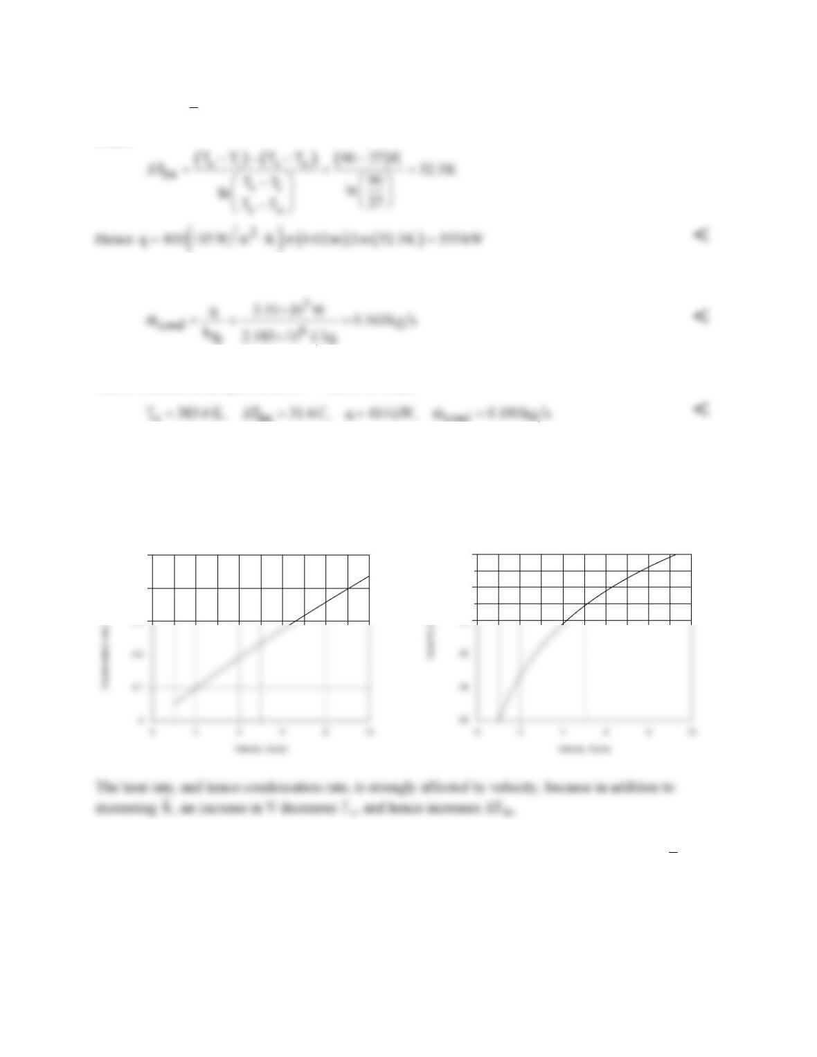
The effect of velocity is shown below.
0.3
0.4
0.5
32
36
40
COMMENTS: (1) The calculations of part (a) should be repeated with air properties evaluated at (Ti +
To)/2. (2) the condensation rate could be increased significantly by using a water–cooled (larger
h
),
rather than an air-cooled, condenser.
PROBLEM 7.76
KNOWN: Temperature of single round air jet.
FIND: Minimum jet diameter for which Equation 7.71 can be applied.
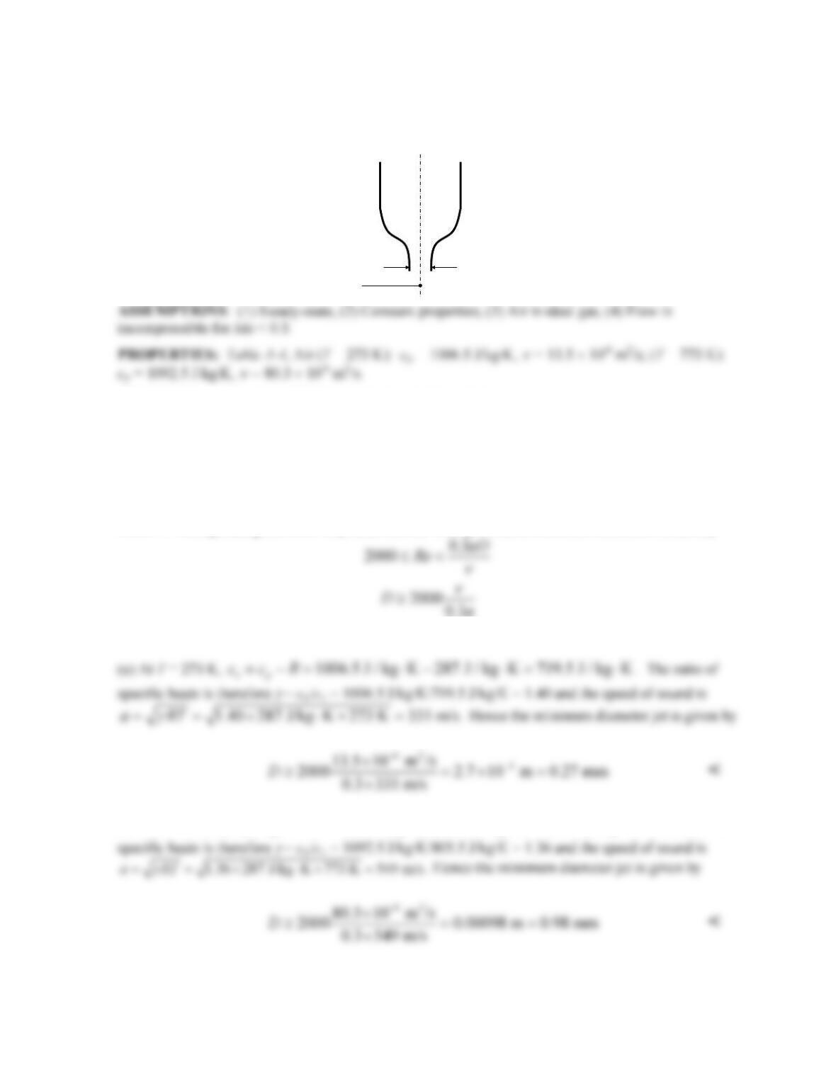
SCHEMATIC:
ANALYSIS: (a) Equation 7.71 is restricted to the Reynolds range:
2000 400,000Re≤≤
With Re = VD/
ν
, this restricts VD, but does not limit D directly. Therefore there must be another
constraint, namely the flow must be incompressible, which is valid for Ma = V/a < 0.3, where a is the
speed of sound. The Mach number constraint implies V < 0.3a, which in turn means that Re <
0.3aD/
ν
. Incorporating the lower Reynolds number limit provides a minimum bound on D, namely
Also, the gas constant for air is R ≡ R/M = 8315 J/kmol∙K/28.97 kg/kmol = 287 J/kg.
1006.5 J / kg K 287 J / kg K 719.5 J / kg K
ccR≡ −= ⋅− ⋅= ⋅
(b) For T = 773 K,
1092.5 J / kg K 287 J / kg K 805.5 J / kg K
vp
ccR≡ −= ⋅− ⋅= ⋅
. The ratio of
COMMENTS: If jet diameters smaller than these limits are to be used, alternative approaches
would need to be taken to estimate the corresponding convection heat transfer rates.
D
min
Air, T
e
= 0°C, 500°C
PROBLEM 7.77
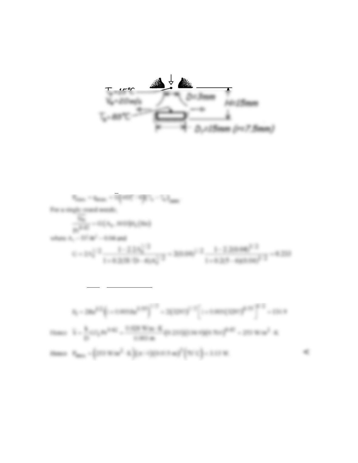
KNOWN: Geometry of air jet impingement on a transistor. Jet temperature and velocity. Maximum
allowable transistor temperature.
FIND: Maximum allowable operating power.
SCHEMATIC:
ASSUMPTIONS: (1) Steady-state conditions, (2) Isothermal surface, (3) Bell-shaped nozzle, (4) All
of the transistor power is dissipated to the jet.
PROPERTIES: Table A-4, Air (Tf = 323 K, 1 atm): ν = 18.2 × 10⁻⁶ m2/s, k = 0.028 W/m⋅K, Pr =
0.704.
ANALYSIS: The maximum power or heat transfer rate by convection is
With
( )
e
-6 2
20 m/s 0.003 m
VD
Re 3297
18.2 10 m / s
ν
= = =
×
COMMENTS: (1) All conditions required for use of the correlation are satisfied.
(2) Power dissipation may be enhanced by allowing for heat loss through the side and base of the
transistor.
PROBLEM 7.78
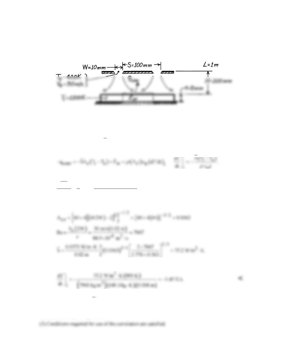
KNOWN: Dimensions of heated plate and slot jet array. Jet exit temperature and velocity. Initial
plate temperature.
FIND: Initial plate cooling rate.
SCHEMATIC:
ASSUMPTIONS: (a) Negligible variation in h along plate, (b) Negligible heat loss from back
surface of plate, (c) Negligible radiation from front surface of plate.
PROPERTIES: Table A-1, AISI 304 Stainless steel (1200 K): k = 28.0 W/m⋅K, cp = 640 J/kg⋅K, ρ
= 7900 kg/m3; Table A-4, Air (
f
T
= 800 K): ν = 84.9 × 10⁻⁶ m2/s, k = 0.0573 W/m⋅K, Pr = 0.709.
ANALYSIS: Performing an energy balance on a control surface about the plate,
i
For an array of slot nozzles,
2/3
3/4
r,o
0.42 r r,o r,o r
Nu 2 2Re
A
3 A /A A /A
Pr
=+
where Ar = W/S = 0.1
Hence,
COMMENTS: (1) Bi =
ht/k
= (73.2 W/m2⋅K) (0.008 m)/28 W/m⋅K = 0.02 and use of the lumped
capacitance method is justified.
(2) Radiation may be significant.
PROBLEM 7.79
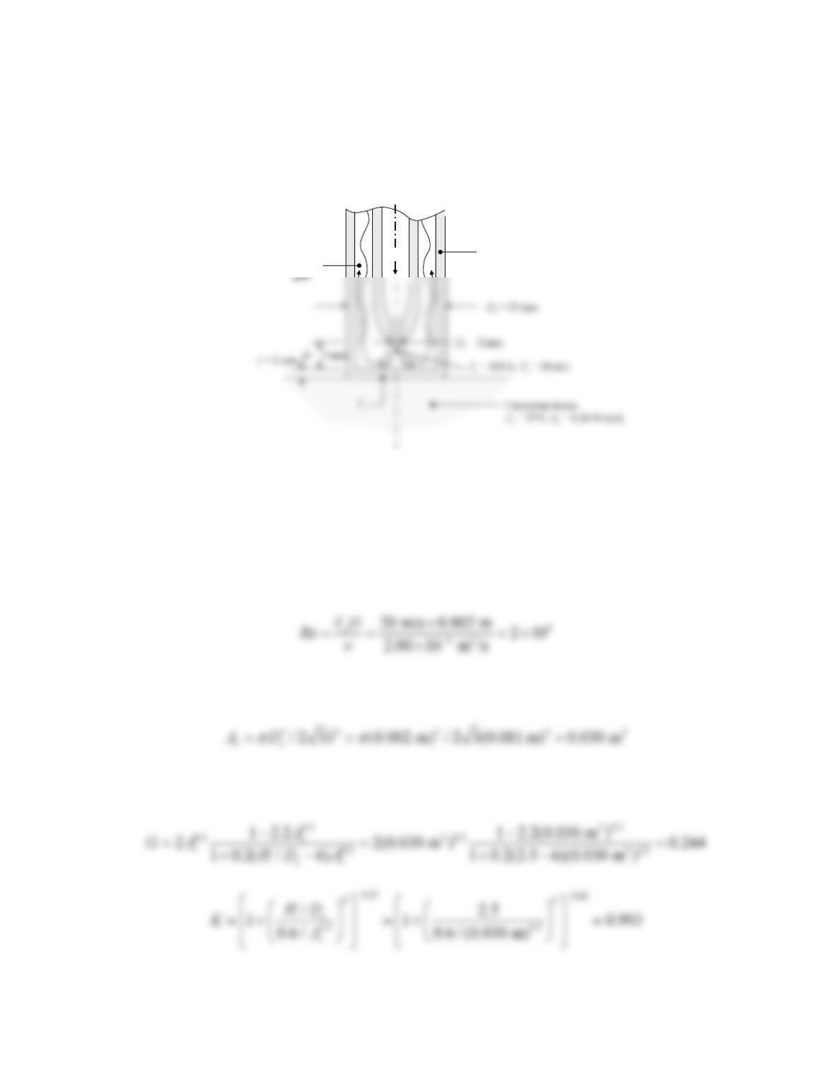
KNOWN: Dimensions and material of a cryogenic probe. Temperature and velocity of nitrogen at jet
exit. Cancerous tissue thermal conductivity and temperature far from the probe.
FIND: (a) Skin surface temperature under probe.
SCHEMATIC:
ASSUMPTIONS: (1) Steady–state conditions, (2) Constant properties, (3) Negligible contact
resistance between skin and probe, (4) Incompressible flow, (5) Due to wall confinement, jet can be
modeled as if it were one in an array.
PROPERTIES: Table A-4, Nitrogen (T
≈
100 K): k = 9.58 × 10⁻³ W/m⋅K,
ν
= 2.00 ×10⁻⁶ m2/s, Pr =
0.768. Table A-1, AISI 302 Stainless Steel (T
≈
300 K): kp = 15.1 W/m⋅K.
ANALYSIS: (a) The Reynolds number is
The jet behaves as if it were in a staggered array, with the probe walls behaving as if they were the
symmetry planes between jets (see Figure 7.18c). Thus S = Do – 2t = 11 mm and
Furthermore, H/De = 2.5. Based on all of these values, the correlation for an array of round nozzles is
valid. From Equations 7.72 and 7.74,
Thus from Equation 7.73,
Continued…
Cryogenic
probe
Spent
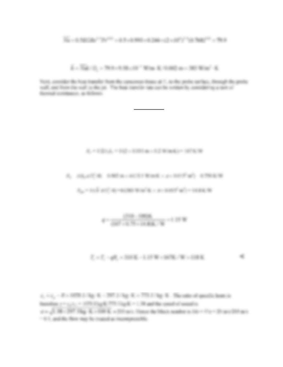
PROBLEM 7.79 (Cont.)
and
jet
ce
cp
TT
qRRR
−
=++
In this expression,
Rc is the resistance associated with the semi–infinite cancerous tissue having a disk of diameter Do at
temperature Ts, as in Table 4.1, Case 10:
Rp represents conduction through the probe wall:
The heat transfer rate is
and q = (Tc – Ts)/Rc, so that
COMMENTS: (1) The assumption of incompressible flow can be checked as follows. For nitrogen,
the gas constant is R ≡ R/M = 8315 J/kmol∙K/28 kg/kmol = 297 J/kg. At 100 K,
PROBLEM 7.80
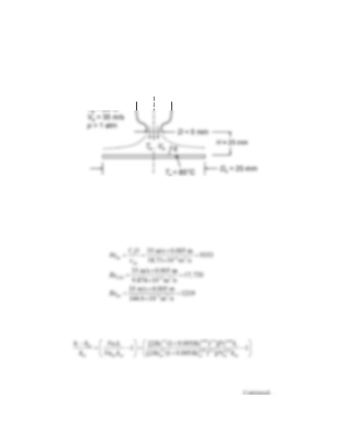
KNOWN: Diameter and temperature of disk–shaped surface cooled by air jet. Nozzle diameter and
distance from surface. Temperature and velocity of air jet.
FIND: Percentage change in average heat transfer coefficient if air replaced with carbon dioxide or
helium.
SCHEMATIC:
Air, CO
2
, or He
s
ASSUMPTIONS: (1) Steady–state incompressible flow conditions, (2) Constant properties, (3)
Negligible radiation effects.
PROPERTIES: Table A-4, Air (T = 328 K):
ν
= 18.71 × 10⁻⁶ m2/s, k = 0.0284 W/m⋅K, Pr = 0.703; CO2
(T = 328 K):
ν
= 9.874 × 10⁻⁶ m2/s, k = 0.0187 W/m⋅K, Pr = 0.751; Helium (T = 328 K):
ν
= 144.6 × 10⁻⁶,
k = 0.162 W/m⋅K, Pr = 0.679.
ANALYSIS: For the three fluids, the Reynolds numbers are:
The Nusselt number is given by Equation 7.71 for a round jet. The parameter G depends only on
geometry. Since we are interested in the percentage change in heat transfer coefficients, G will cancel out.
That is, comparing fluid i to air:
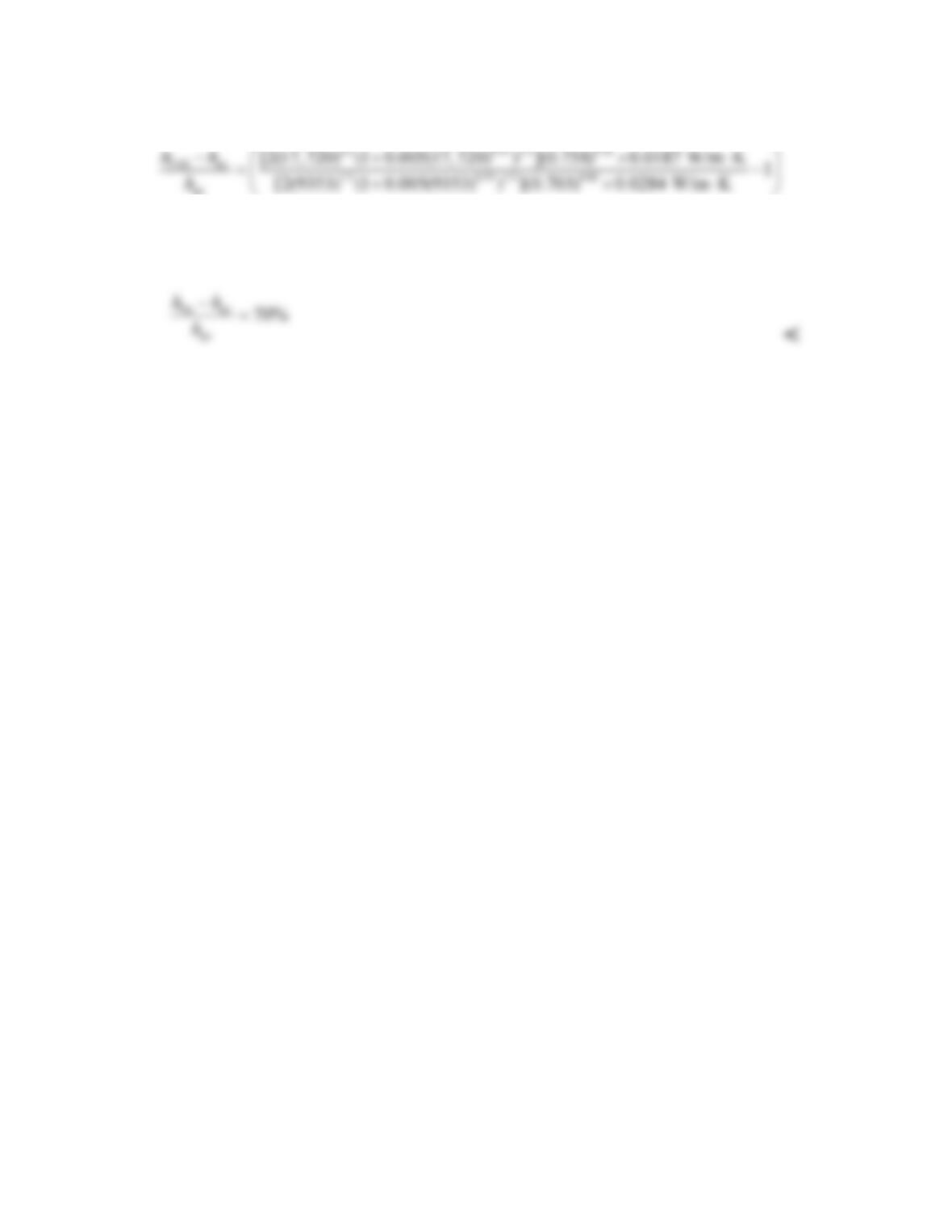
PROBLEM 7.80 (Cont.)
For CO2,
air
1.3%=
<
Similarly for helium,
COMMENTS: The correlation was extrapolated outside of its Reynolds number range for helium.