Problem 7-10
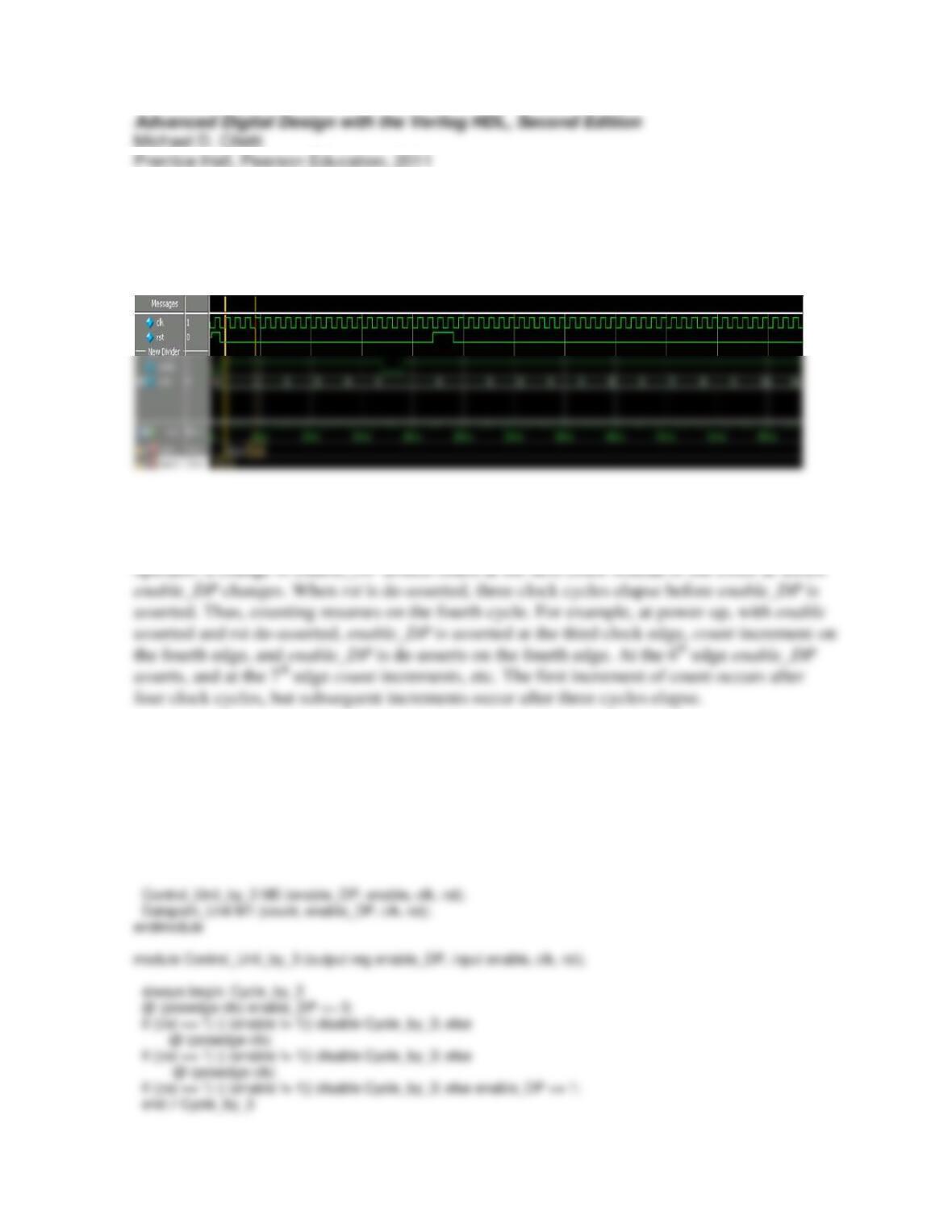
The waveforms below show that the machine takes four clock cycles to recover from a reset
condition.
The code for Binary_Counter_Part_RTL_by_3 is given below. Note that Control_Unit_by_3
is an implicit state machine, and that enable_DP is a Moore output of the machine. The reset
action is synchronous. Because enable_DP and count are assigned value by a nonblocking
The control unit can be modified so that the machine recovers from a reset in three cycles and
incrments the counter in three cycles too.
module Binary_Counter_Part_RT_by_3 #(parameter size = 4) (
output [size -1: 0] count,
input enable, clk, rst
);
wire enable_DP;
endmodule
module Datapath_Unit # (parameter size = 4) (
output reg [size -1: 0] count,
input enable, clk, rst
);
The control unit is modified to form modified_Binary_Counter_Part_RTL as listed below.
module modified_Binary_Counter_Part_RTL #(parameter size = 4) (
output [size -1: 0] count,
input enable, clk, rst
);
wire enable_DP;
forever begin: inner_loop
@ (posedge clk) enable_DP <= 0;
if first == 1) || (enable != 1)) disable Cycle_by_3; else
@ (posedge clk)
if first == 1) || (enable != 1)) disable Cycle_by_3; else
@ (posedge clk)
if first == 1) || (enable != 1)) disable Cycle_by_3; else enable_DP <= 1;
end // inner_loop
end // Cycle_by_3
endmodule
module t_modified_Binary_Counter_Part_RTL #(parameter size = 4) ();
wire [size -1: 0] count;
reg enable, clk, rst;
initial #700 $finish;
initial begin clk = 0; forever #5 clk = ~clk; end
initial fork
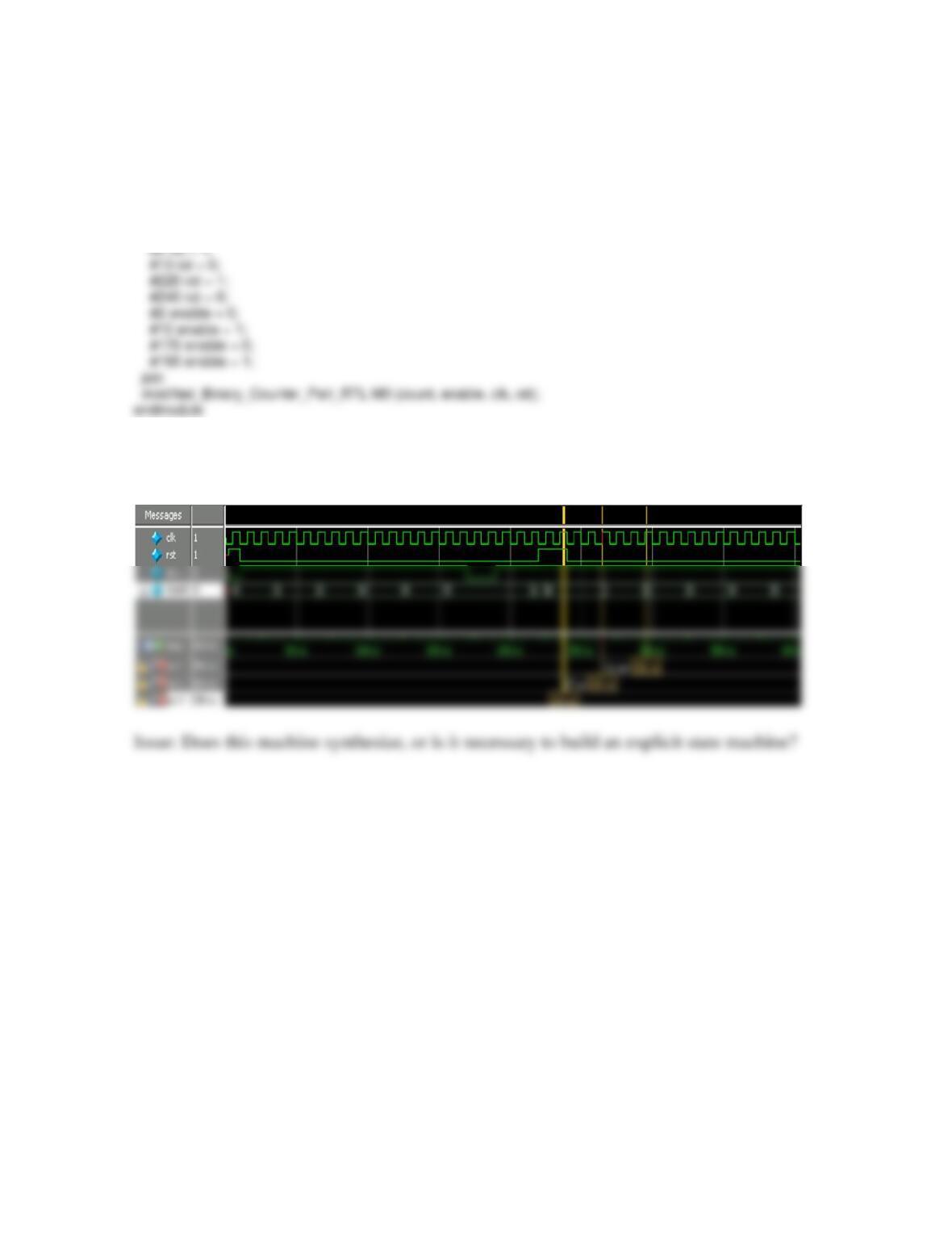
The simulation results below show that count recovers in three clock cycles after rst is de-
asserted.
Problem 7-11
module Binary_Counter_Part_RTL_by_3 #(parameter size = 4)(
output [size -1: 0] count,
input enable,
input clk, rst
always @ (posedge clk) if (rst == 1) state <= s0; else state <= next_state;
always @(state, enable) begin
enable_DP = 0;
case (state)
s0: begin next_state = s1; end
s1: begin next_state = s2; end
if first == 1) || (enable != 1)) disable Cycle_by_3; else
@ (posedge clk)
if first == 1) || (enable != 1)) disable Cycle_by_3; else
@ (posedge clk)
if first == 1) || (enable != 1)) disable Cycle_by_3;
function [size-1: 0] next_count;
input [size-1:0] count;
begin
next_count = count + 1;
end
endfunction
endmodule
initial fork
#2 begin rst = 1; enable = 0; end
#10 rst = 0;
#20 enable = 1;
#120 enable = 0;
#140 enable = 1;
#160 rst = 1;

Problem 7-14
module Prob_7_14 (output reg [2: 0] segment, input [15: 0] value);
always @ (value) case (value)
(0 <= value) && (value <= 8191): segment = 0;
(8192 <= value) && (value <= 8191): segment = 0;
Problem 7-15
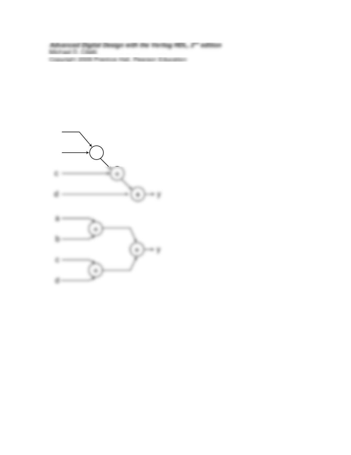
The first description will synthesize combinational logic in which the longest path traverses
three adders. The use of parentheses in the second description directs the synthesis tool to
synthesize a circuit in which the longest path traverses only two adders.
+
a
b
Problem 7-17
1
rst
S_idle
clr_P1_P0: {P1, P0} <= {0, 0}
module Prob_7_17 (output [15: 0] R0, input [7: 0] Data, input En, Ld, clock, reset);
wire clr_P1_P0, Ld_R0, Ld_P1_P0;
P7_17_Control_Unit M0 (clr_P1_P0, Ld_R0, Ld_P1_P0, En, Ld, clock, reset);
P7_17_Datapath_Unit M1 (R0, Data, clr_P1_P0, Ld_R0, Ld_P1_P0,clock, reset);
endmodule
always @ (state, En, Ld) begin
next_state = S_idle;
clr_P1_P0 = 0;
Ld_R0 = 0;
Ld_P1_P0 = 0;
case (state)
next_state = S_1; Ld_P1_P0 = 1;
end
default: next_state = S_idle;
endcase
end
endmodule
module P7_17_Datapath_Unit (output reg [15: 0] R0, input [7: 0] Data, input clr_P1_P0, Ld_R0, Ld_P1_P0,
clock, reset);
reg [7:0] P0, P1;
always @(posedge clock, posedge reset)
if (reset == 1’b1) begin
module t_Prob_7_17 ();
wire [15: 0] R0;
reg [7: 0] Data;
reg En, Ld, clock, reset;
Prob_7_17 M0 (R0, Data, En, Ld, clock, reset);
initial begin #300 $finish; end
#120 En = 1;
#160 Ld = 1; // Loop through S_full, S_1
#180 En = 0; // Return to S_idle
join
endmodule
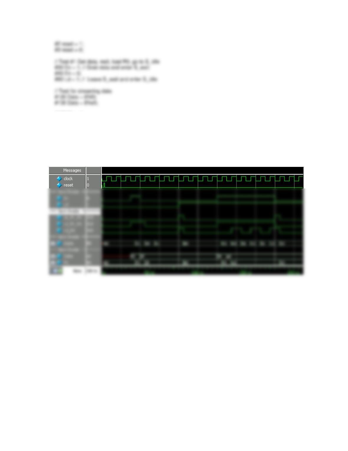
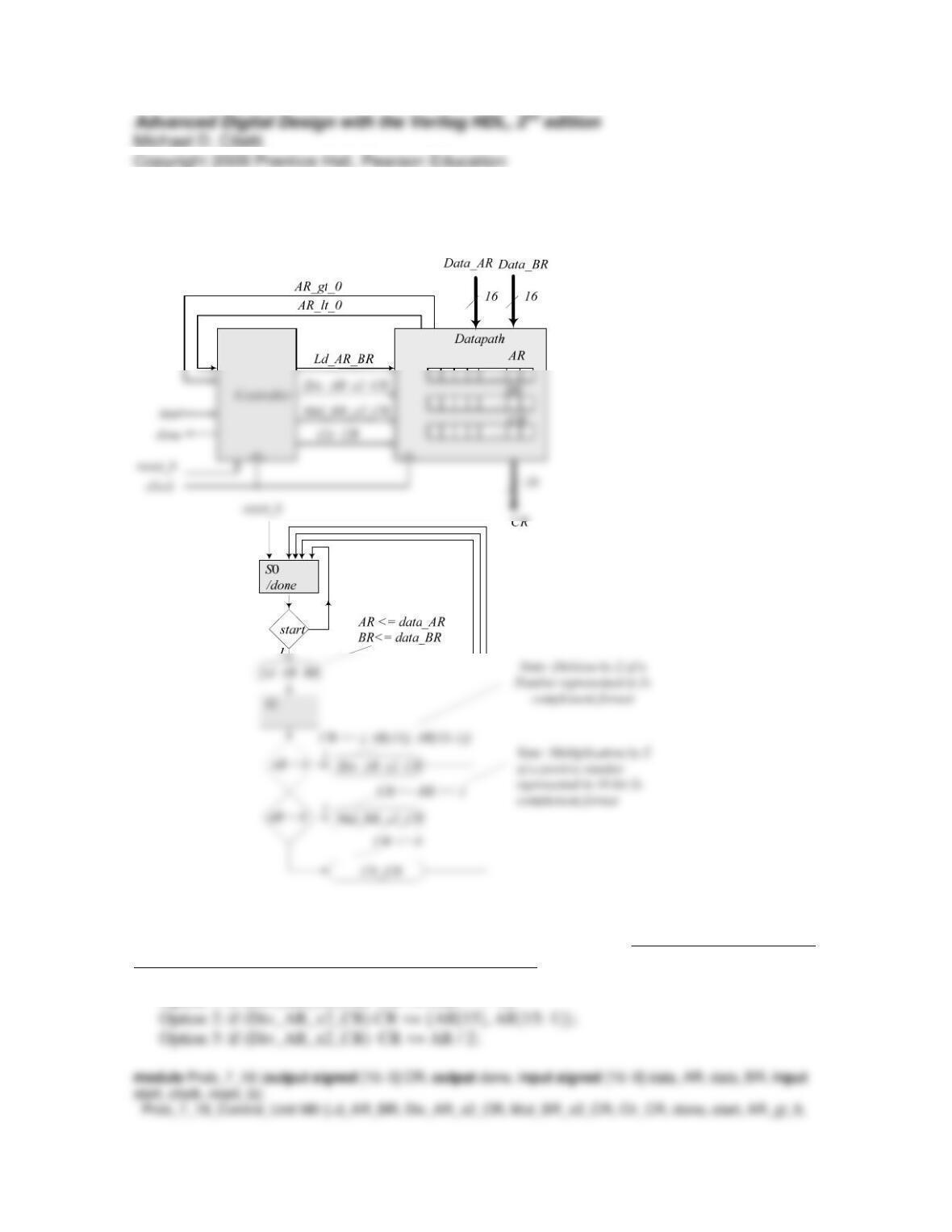
Simulation results for a partial test of the machine are shown below. Tests for additional paths through
the STG are left to the student.
Problem 7-18
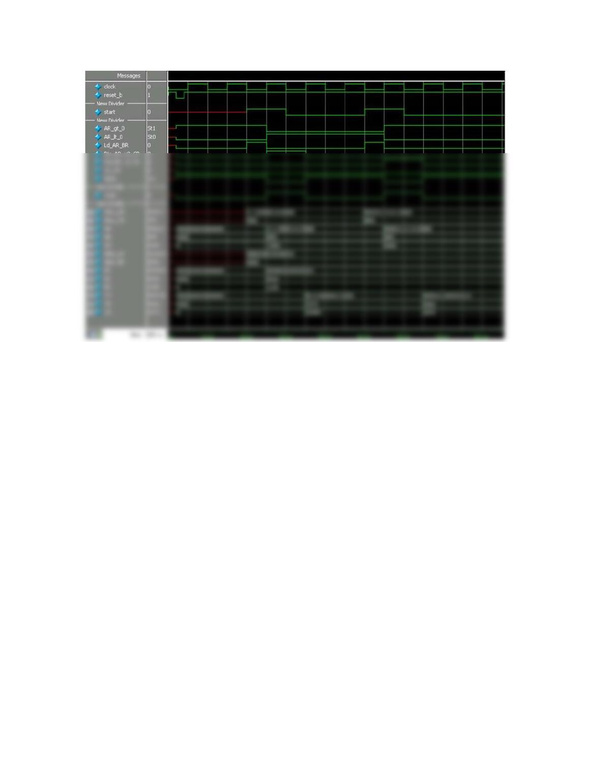
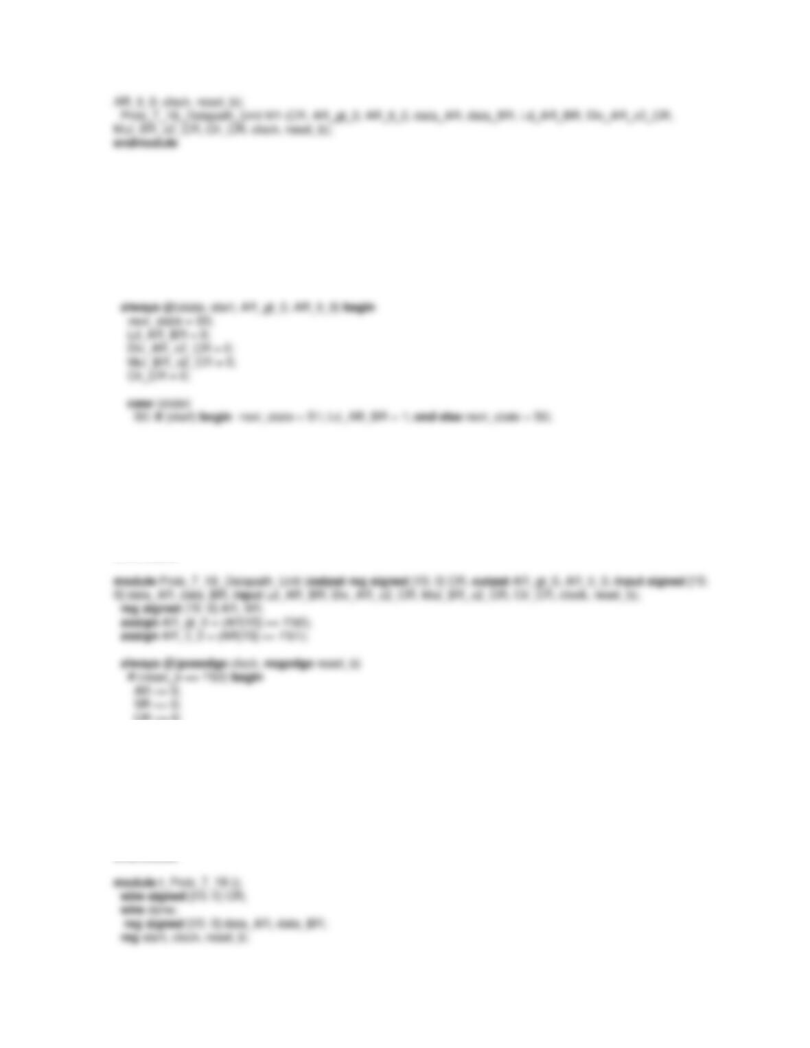
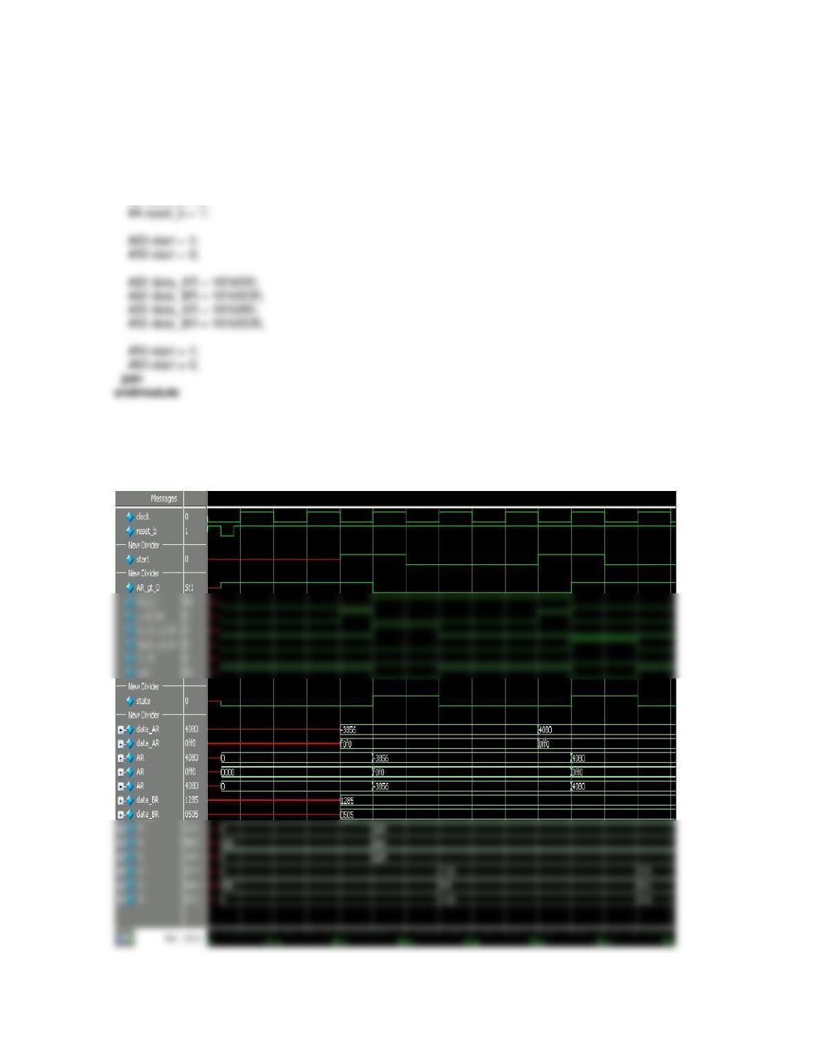
The simulation results below were obtained using the signed declarations shown in the code.
The three options shown below for dividing AR, a negative value, produce the same results
only if the relevant variables are declared to be signed.
Option 1: if (Div_AR_x2_CR) CR <= (AR >>> 1);
module Prob_7_18_Control_Unit (output reg Ld_AR_BR, Div_AR_x2_CR, Mul_BR_x2_CR, Clr_CR, output
done, input start, AR_gt_0, AR_lt_0, clock, reset_b);
reg state, next_state;
parameter S0 = 0, S1 = 1;
assign done = (state == S0);
always @(posedge clock, negedge reset_b)
if (reset_b == 0) state <= S0;
else state <= next_state;
S1: begin
next_state = S0;
if (AR_lt_0)Div_AR_x2_CR = 1;
else if (AR_gt_0 > 0) Mul_BR_x2_CR = 1;
else Clr_CR = 1;
end
endcase
end
endmodule
CR <= 0;
end
else begin
if (Ld_AR_BR) begin AR <= data_AR; BR <= data_BR; end
//if (Div_AR_x2_CR) CR <= (AR >>> 1);
if (Div_AR_x2_CR) CR <= {AR[15], AR[15: 1]};
//if (Div_AR_x2_CR) CR <= AR / 2;
if (Mul_BR_x2_CR) CR <= (BR << 1);
if (Clr_CR) CR <= 0;
end
endmodule
Prob_7_18 M0(CR, done, data_AR, data_BR, start, clock, reset_b);
initial #2000 $finish;
initial begin clock = 0; forever #5 clock = ~clock; end
initial fork
reset_b = 1;
#2 reset_b = 0;
The figure below shows simulation results when the variables are not signed. Waveforms are
shown in decimal, hexadecimal, and decimal formats, for comparison
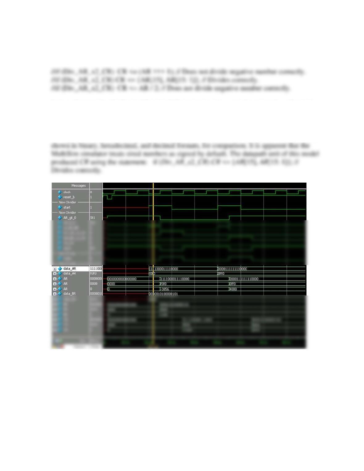
If the variables are not declared signed, the results are mixed:
It is not known why the first (arithmetic shift operator) and second do not produce identical
results. An alternative algorithm would be to first find the magnitude of a negative value, then
divide by shifting, then convert back to a 2s complement representation.
The figure below shows simulation results when the variables are not signed. Waveforms are
Incorrect waveforms are produced by MultiSim when the datapath unit forms CR using:
if (Div_AR_x2_CR) CR <= AR / 2; // Does not divide negative number correctly.
The decimal value of the result is incorrect.