PROBLEM 7.14 (Cont.)
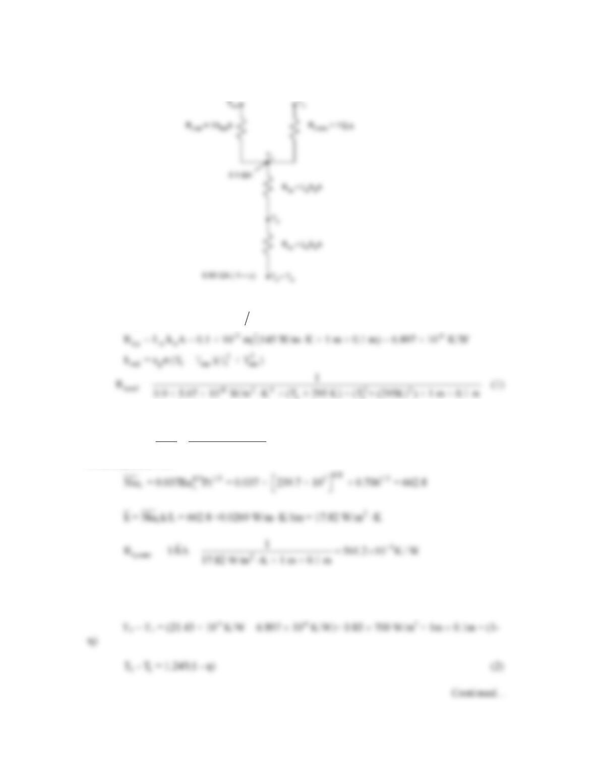
The thermal resistances are
-3 -3
t,g g g
R = L /k A = 3 × 10 m (1.4 W/m K × 1 m × 0.1 m) = 21.43 × 10 K/W⋅
11
For the tripped boundary layer,
3
m
L-5 2
uL 4m/s 1m
Re = = = 239.7×10
1.669 × 10 m /s
×
ν
From Equation 7.38
From the thermal circuit,
3 1 t,g t,a 3 1 t,g t,a
0.83GA (1 – η) = (T – T )/(R + R ) or T – T = (R + R ) 0.83GA (1 – η)
PROBLEM 7.14 (Cont.)
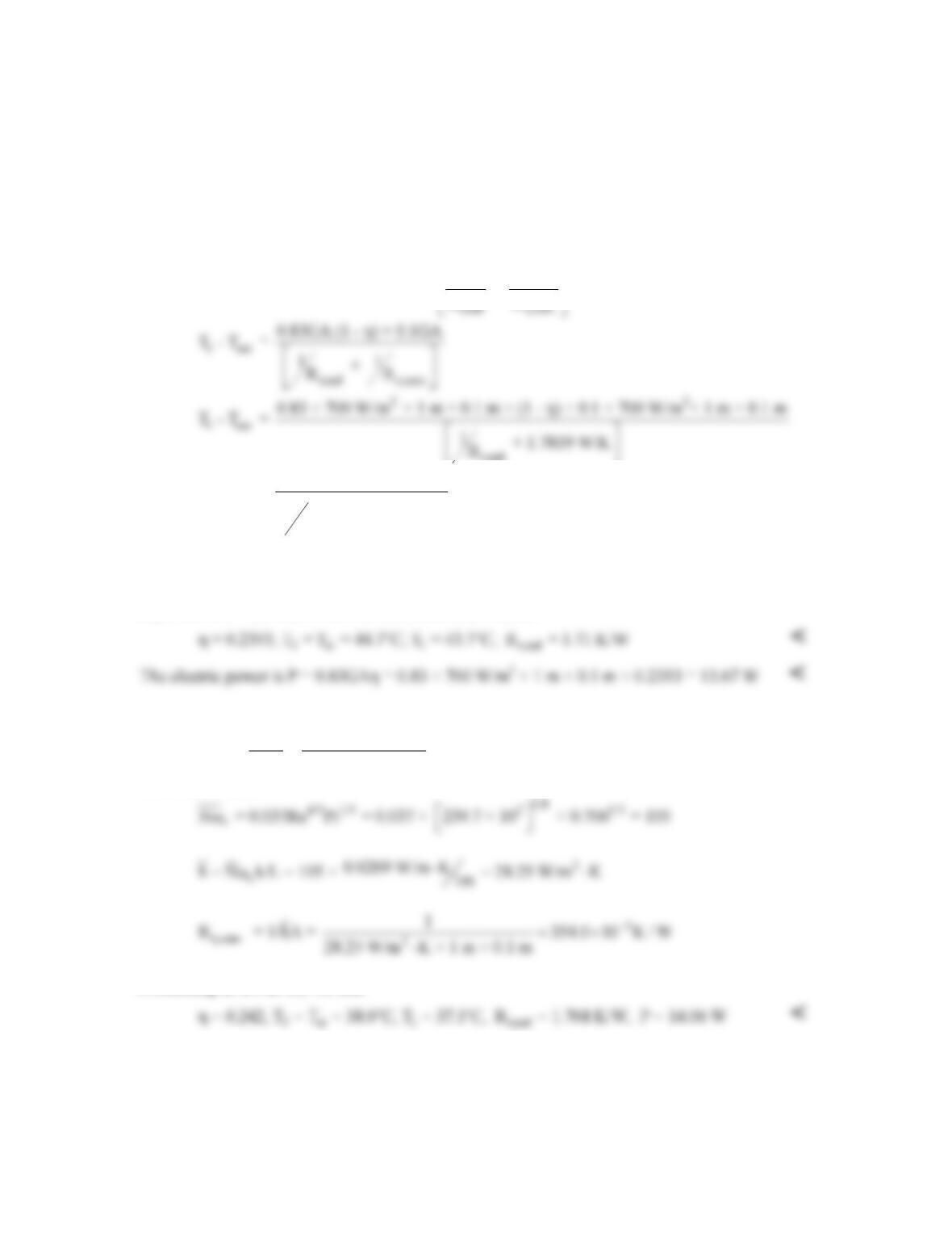
We also note from the thermal circuit,
1 sur t,rad 1 t,conv
0.83GA (1 – η) + 0.1G = (T – T )/R + (T – T )/R
∞
Since T∞ = Tsur
1 sur
11
0.83GA (1 – η) + 0.1G = (T – T ) +
RR
t,rad
1 sur
t,rad
58.1 W (1 – η) + 7 W
T – T =
1+ 1.7819 W/K
R
(3)
where η = 0.28 – 0.001°C-1 × (T3 – 273)°C (4)
Equations (1) – (4) may be solved simultaneously to yield
(b) For the tripped boundary layer
2
m
L-5 2
uL 4/ms 0.1m
Re = = = 239.7×10
1.669 × 10 m /s
×
ν
From Equation 7.38
Proceeding as in Part (a) we find
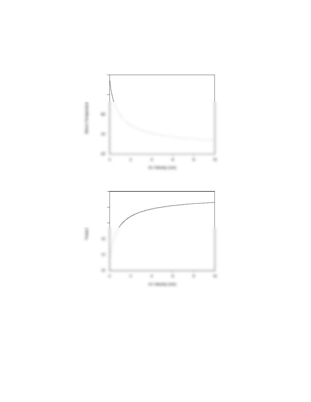
(c) Solving Equations 1 through 4 over the velocity range 0 ≤ um ≤ 10 m/s yields the following
behavior
Continued…
PROBLEM 7.14 (Cont.)
Silicon Temperature vs. Air Velocity
80
100
Electric Power vs Air Velocity
13
14
15
COMMENTS: (1) Changing the orientation of the solar panel to the L = 0.1 m configuration
reduces the temperature of the silicon semiconductor significantly. The influence of the
orientation on the electric power would be more pronounced for warmer air temperatures. (2)
Decreasing the air velocity results in significantly diminished power output. At very low cross
flow velocities, natural convection would become significant and would lead to slightly improved
power output relative to that predicted here. (3) Film temperatures for Parts (a) and (b) are 31.9
°C and 28.6 °C, respectively. The assumed value of the film temperature is good.
PROBLEM 7.15
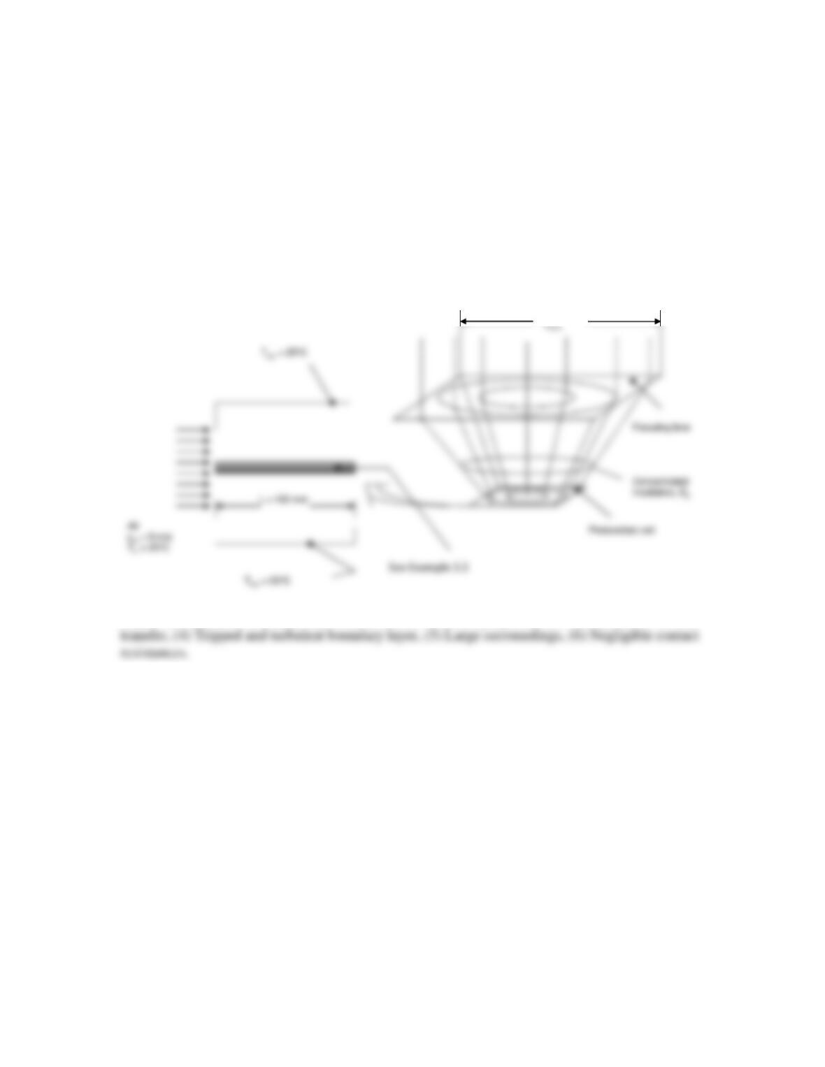
KNOWN: Dimensions of a photovoltaic cell, cooling air velocity and temperature, size of
concentrating lens, photovoltaic construction and properties.
FIND: (a) The electric power output and silicon temperature of a system consisting of a 400 mm
× 400 mm concentrating lens and a 100 mm × 100 mm photovoltaic cell, (b) Variation of the
electric power output and silicon temperature for 100 mm ≤ Llens ≤ 600 mm.
SCHEMATIC:
Solar irradiation, G
Solar irradiation, G
ASSUMPTIONS: (1) Steady-state conditions, (2) Constant properties, (3) One-dimensional heat
PROPERTIES: Given, Glass: kg = 1.4 W/m∙K, εg = 0.90, Adhesive: ka = 145 W/m∙K, Solder, ks
= 50 W/m∙K, Aluminum nitride: kan = 120 W/m∙K, Table A.4, air (assume Tf = 70°C): k =
0.02948 W/m⋅K, ν = 2.022 × 10⁻⁵ m2/s, Pr = 0.701.
ANALYSIS:
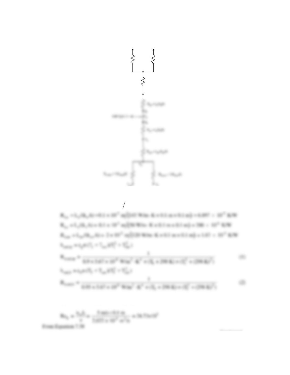
(a) We begin by drawing the thermal circuit,
Continued…
PROBLEM 7.15 (Cont.)
R
t,conv
= 1/(h
conv
A)
T
∞
T
sur
R
t,rad,tp
= 1/(h
rad,tp
A)
T
1
R
t,g
= L
g
/(k
g
A)
T
2
∞
sur
R
t,conv
= 1/(h
conv
A)
T
∞
T
sur
R
t,rad,tp
= 1/(h
rad,tp
A)
T
1
R
t,g
= L
g
/(k
g
A)
T
2
∞
sur
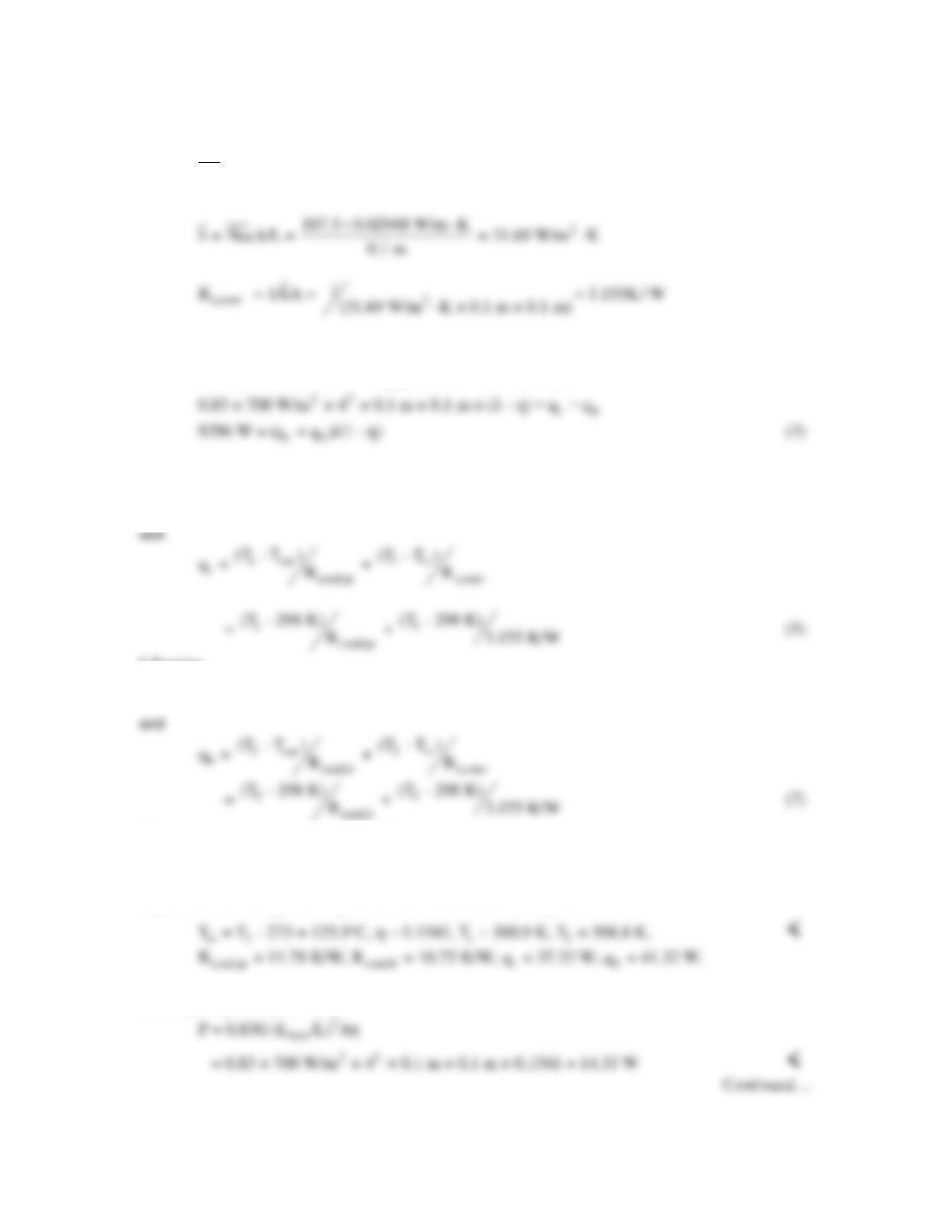
The thermal resistances are
( )
-3
t,g g g
R = L /(k A) = 3 × 10 m 1.4 W/m K × 0.1 m × 0.1 m = 0.2143 K/W⋅
R = L /(k A) =0.1 × 10 m 145 W/m K × 0.1 m × 0.1 m = 6.897 10 K/W⋅×
For the top and bottom tripped boundary layers,
Continued…
PROBLEM 7.15 (Cont.)
0.8
4/5 1/3 3 1/3
LL
Nu = 0.037Re Pr = 0.037 × 24.73 × 10 × 0.701 = 107.5
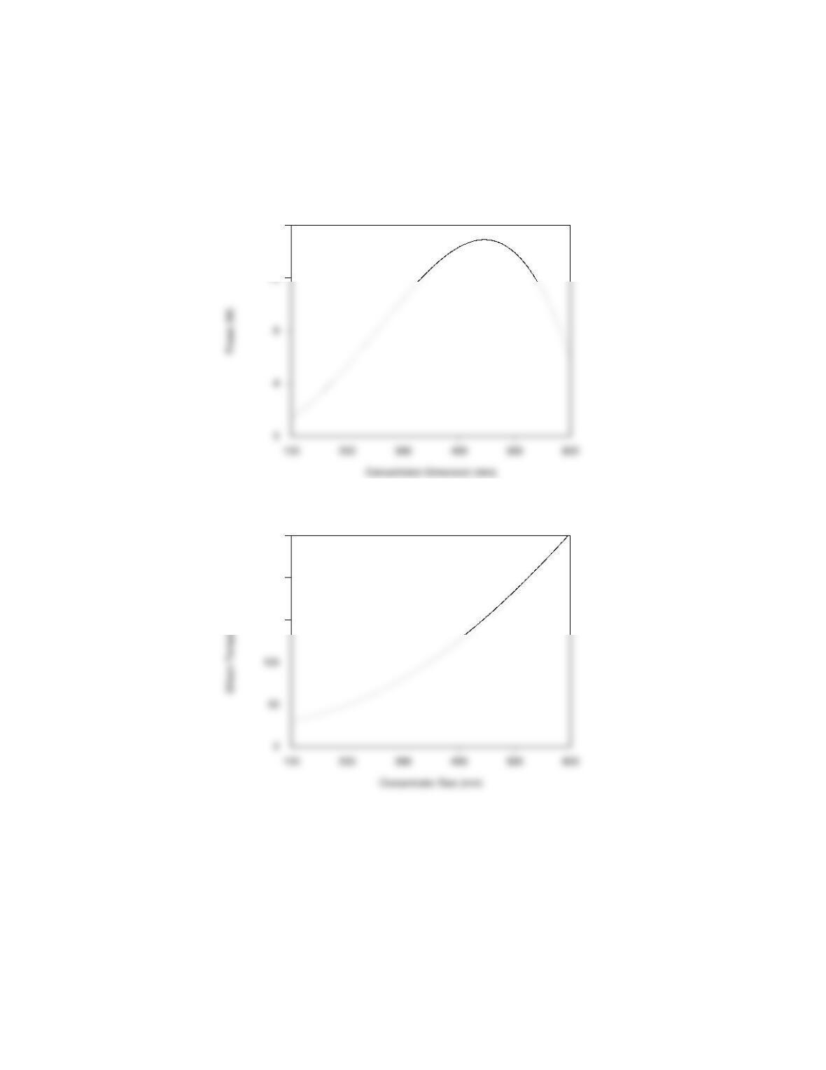
From the thermal circuit,
2
c lens t b
0.83G A (1 – η) = 0.83G (L /L) A(1 – η) = q + q
where
qt = (T3 – T1) /(Rt,a + Rt,g) = (T3 – T1) /0.2144 K/W (4)
Likewise
qb = (T3 – T5) /(Rt,s + Rt,an) = (T3 – T5) /1.87 × 10-3 K/W (6)
The solar–to–electrical conversion efficiency is
-1
3
η = 0.28 – 0.001°C × (T – 273)°C
(8)
Equations (1) through (8) may be solved simultaneously to yield
The electric power produced is
PROBLEM 7.15 (Cont.)
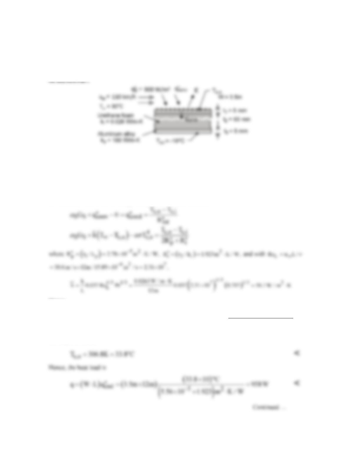
(b) The IHT Software may be used to investigate the sensitivity of the silicon temperature and the
electric power produced in response to the concentrating lense size. Results are shown below. <
Electric Power vs Concentrator Size
16
Silicon Temperature vs Concentrator Size
150
200
250
COMMENTS: (1) The electric power output is highly sensitive to the size of the concentrating
lens The concentrated irradiation continually increases as the concentrator is made larger until,
eventually, the silicon temperature becomes very high and the solar–to–electrical conversion
efficiency becomes small. (2) The electric power could be increased if heat sinks and/or liquid
cooling could be applied to the solar cell, keeping the silicon temperature low and the conversion
efficiency relatively high. (3) The assumed film temperature is a good estimate since Tf,tp = 71.4
°C and Tf,bot = 75.4 °C.
PROBLEM 7.16
KNOWN: Material properties, inner surface temperature and dimensions of roof of refrigerated
truck compartment. Truck speed and ambient temperature. Solar irradiation.
FIND: (a) Outer surface temperature of roof and rate of heat transfer to compartment, (b) Effect of
changing radiative properties of outer surface, (c) Effect of eliminating insulation.
ASSUMPTIONS: (1) Negligible irradiation from the sky, (2) Turbulent flow over entire outer
surface, (3) Average convection coefficient may be used to estimate average surface temperature, (4)
Constant properties.
PROPERTIES: Table A-4, air (p = 1 atm, Tf ≈ 300K): ν = 15.89 × 10⁻⁶ m2/s, k = 0.0263 W/m⋅K,
Pr = 0.707.
ANALYSIS: (a) From an energy balance for the outer surface,
Hence,
( )
( )
( )
s,o
2 2 8 2 44
s,o s,o 52
T 263K
0.6 900 W / m K 56.1 W / m K 303 T 0.6 5.67 10 W / m K T
5.56 10 1.923 m K / W
−
−
−
⋅+ ⋅ − −× × ⋅ =
×+ ⋅
Solving, we obtain
PROBLEM 7.16 (Cont.)
(b) With the special surface finish
( )
S0.20, 0.8 ,
αε
= =
(c) Without the insulation (t2 = 0) and with αS = ε = 0.6,
COMMENTS: (1) Use of the special surface finish reduces the solar input, while increasing
radiation emission from the surface. The cumulative effect is to reduce the heat load by 17%. (2) The
thermal resistance of the aluminum panels is negligible, and without the insulation, the heat load is
enormous.
PROBLEM 7.17
KNOWN: Surface characteristics of a flat plate in an air stream.
FIND: Orientation which minimizes convection heat transfer and the corresponding heat
transfer rate.
SCHEMATIC:
ASSUMPTIONS: (1) Surface B is sufficiently rough to trip the boundary layer when in the
upstream position (Configuration 2).
PROPERTIES: Table A-4, Air (Tf = 296 K, 1 atm): ν = 15.5 × 10⁻⁶ m2/s, k = 26.0 × 10⁻³
W/m⋅K, Pr = 0.708.
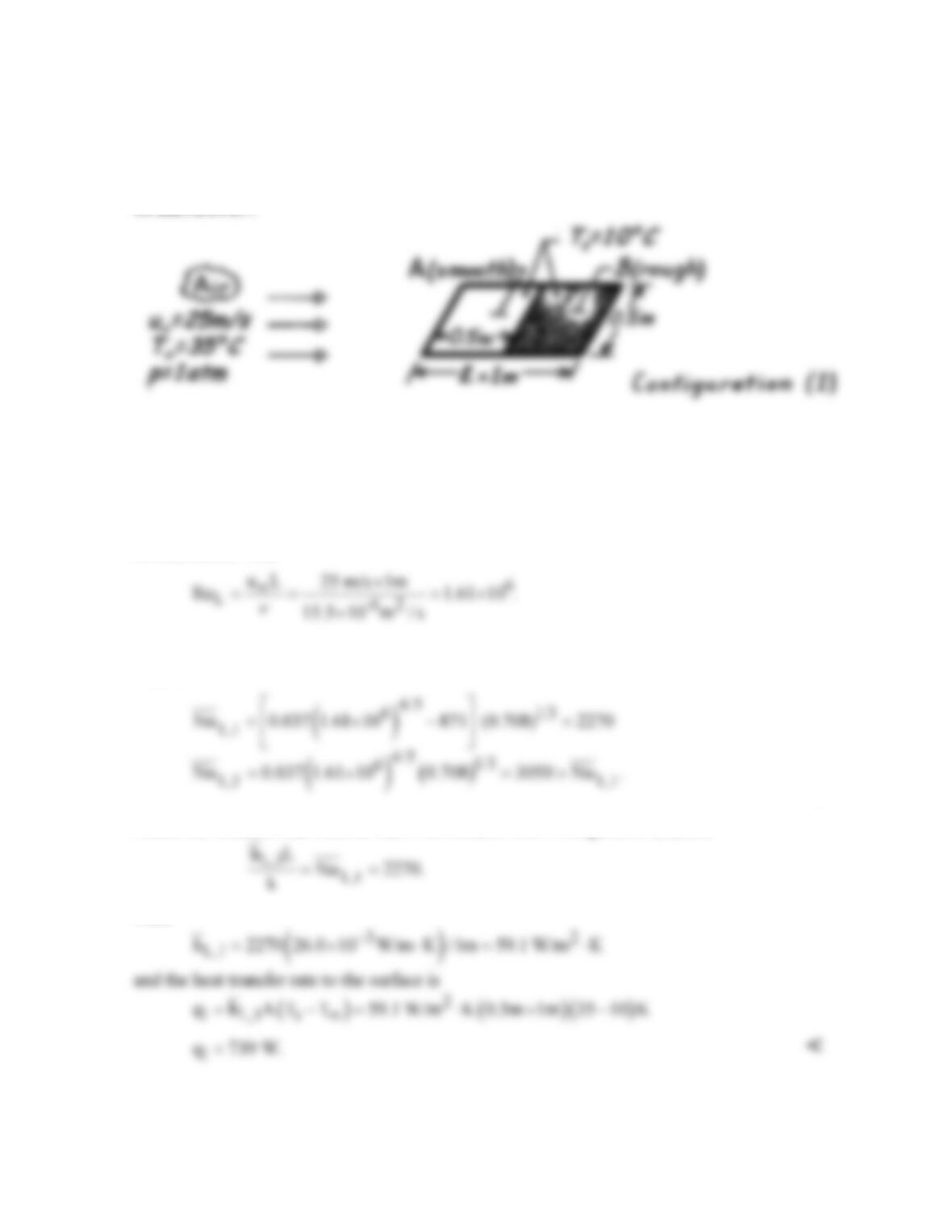
ANALYSIS: Find
Hence in Configuration (1), transition will occur just before the rough surface (xc = 0.31 m).
Note that
Hence the smallest heat transfer rate is associated with Configuration (1), and: <
Thus
PROBLEM 7.18
KNOWN: Dimensions and orientation of a flat plate placed in atmospheric airstream, airstream
velocity and temperature, plate temperature.
FIND: The average convection coefficient for the entire surface.
ASSUMPTIONS: (1) Steady-state conditions, (2) Constant properties, (3) Boundary layer on rough
plate is tripped at leading edge, (4) Transition occurs at Rex,c = 500,000.
PROPERTIES: Table A.4, air (Tf = 296 K, p = 1 atm):
ν
= 15.5 ×10⁻⁶ m2/s, Pr = 0.708, k = 0.0260
W/m⋅K.
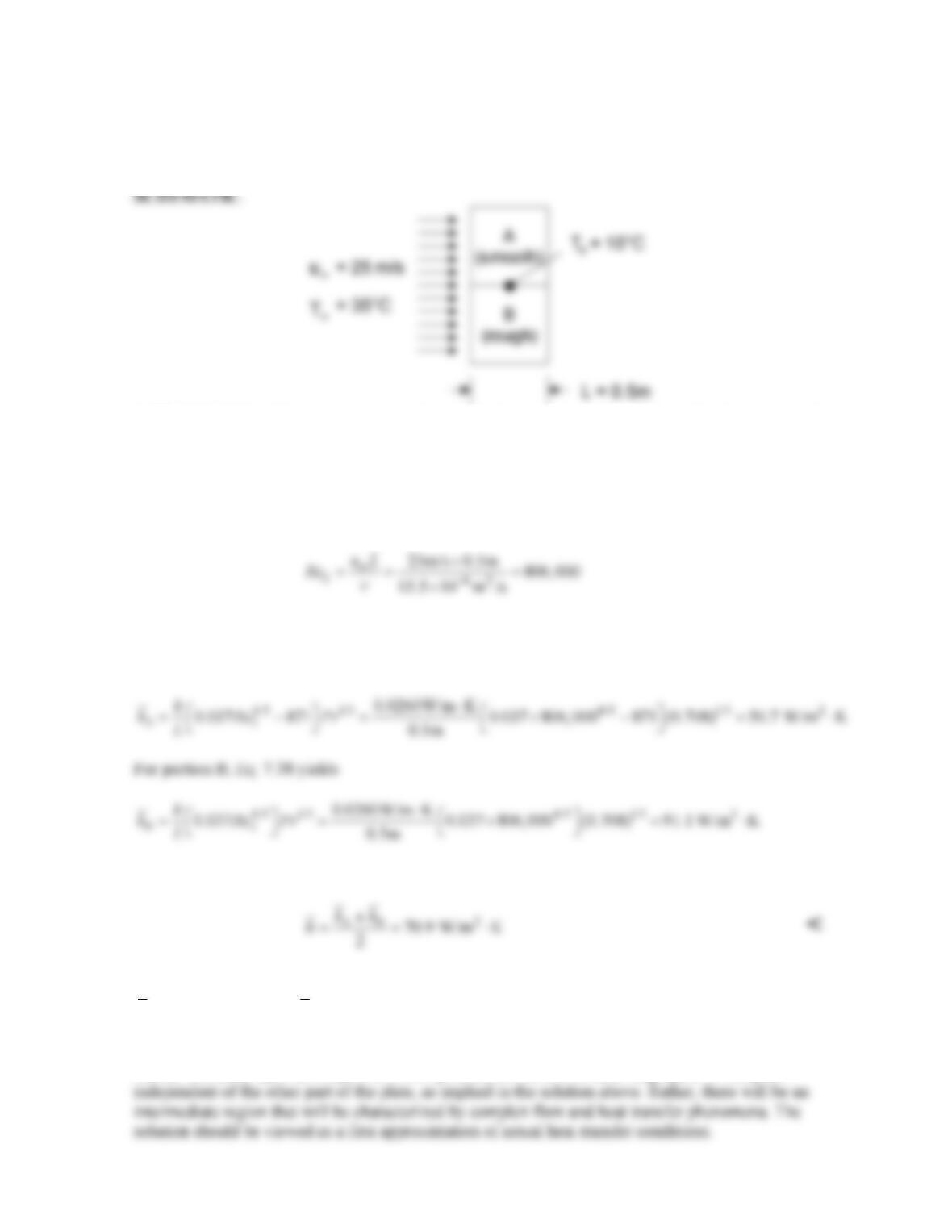
ANALYSIS: For both the smooth and rough sections of the plate,
Therefore, flow over portion A of the plate is mixed, with xc = 0.31 m.
For portion A, Eq. 7.38 yields
Therefore, for the entire plate consisting of half portion A and half portion B,
COMMENTS: (1) The value of the average coefficient for orientations 1 and 2 of Problem 7.17 are
2
159.1 W/m Kh= ⋅
and
2
279.3 W/m Kh= ⋅
, respectively. The average heat transfer coefficient found
here is approximately midway between the values associated with the other two orientations. This is
coincidental, since the nature of the flow is very different for the three different orientations. (2) In
reality, boundary layer development cannot proceed on the smooth and rough parts of the plate
PROBLEM 7.19
KNOWN: Plate dimensions and initial temperature. Velocity and temperature of air in parallel flow
over plates.
FIND: Initial rate of heat transfer from plate. Rate of change of plate temperature.
SCHEMATIC:
ASSUMPTIONS: (1) Negligible radiation, (2) Negligible effect of conveyor velocity on boundary
layer development, (3) Plates are isothermal, (4) Negligible heat transfer from sides of plate, (5)
5
x,c
Re 5 10 ,= ×
(6) Constant properties.
PROPERTIES: Table A-1, AISI 1010 steel (573K): kp = 49.2 W/m⋅K, c = 549 J/kg⋅K, ρ = 7832
kg/m3. Table A-4, Air (p = 1 atm, Tf = 433K): ν = 30.4 × 10⁻⁶ m2/s, k = 0.0361 W/m⋅K, Pr = 0.688.
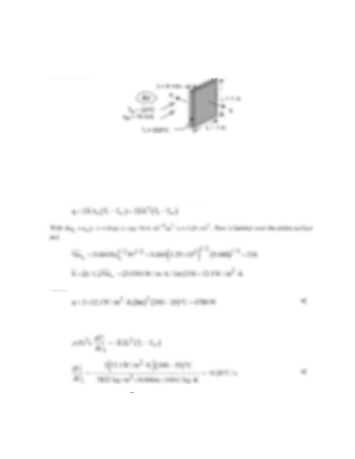
ANALYSIS: The initial rate of heat transfer from a plate is
L
Hence,
Performing an energy balance at an instant of time for a control surface about the plate,
out st
E E,−=
we obtain,
COMMENTS: (1) With
( )
4
p
Bi h / 2 / k 7.4 10 ,
δ
−
= = ×
use of the lumped capacitance method is
appropriate. (2) Despite the large plate temperature and the small convection coefficient, if adjoining
plates are in close proximity, radiation exchange with the surroundings will be small and the
assumption of negligible radiation is justifiable.
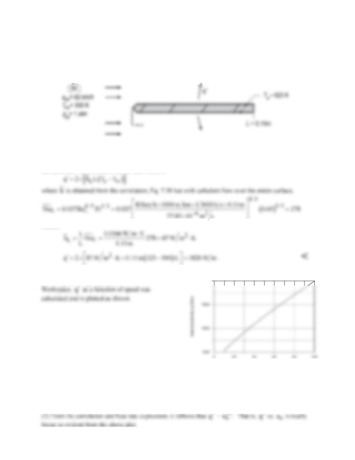
PROBLEM 7.20
KNOWN: Length and surface temperature of a rectangular fin.
FIND: (a) Heat removal per unit width,
q′
, when air at a prescribed temperature and velocity is in parallel,
turbulent flow over the fin, and (b) Calculate and plot
q′
for motorcycle speeds ranging from 10 to 100 km/h.
SCHEMATIC:
ASSUMPTIONS: (1) Steady–state conditions, (2) Negligible radiation, (3) Turbulent flow over entire surface.
PROPERTIES: Table A.4, Air (412 K, 1 atm): ν = 27.85 × 10⁻⁶ m2/s, k = 0.0346 W/m⋅K, Pr = 0.69.
ANALYSIS: (a) The heat loss per unit width is
Hence,
(b) Using the foregoing equations in the IHT
q′
Motorcycle speed, uinf (m/s)
7000
COMMENTS: (1) Radiation emission from the fin is not negligible. With an assumed emissivity of ε =
1, the rate of emission per unit width at 80 km/h would be
q′
=
()
4
s
T 2L
s
= 1273 W/m. If the fin
received negligible radiation from its surroundings, its loss by radiation would then be approximately
20% of that by convection.
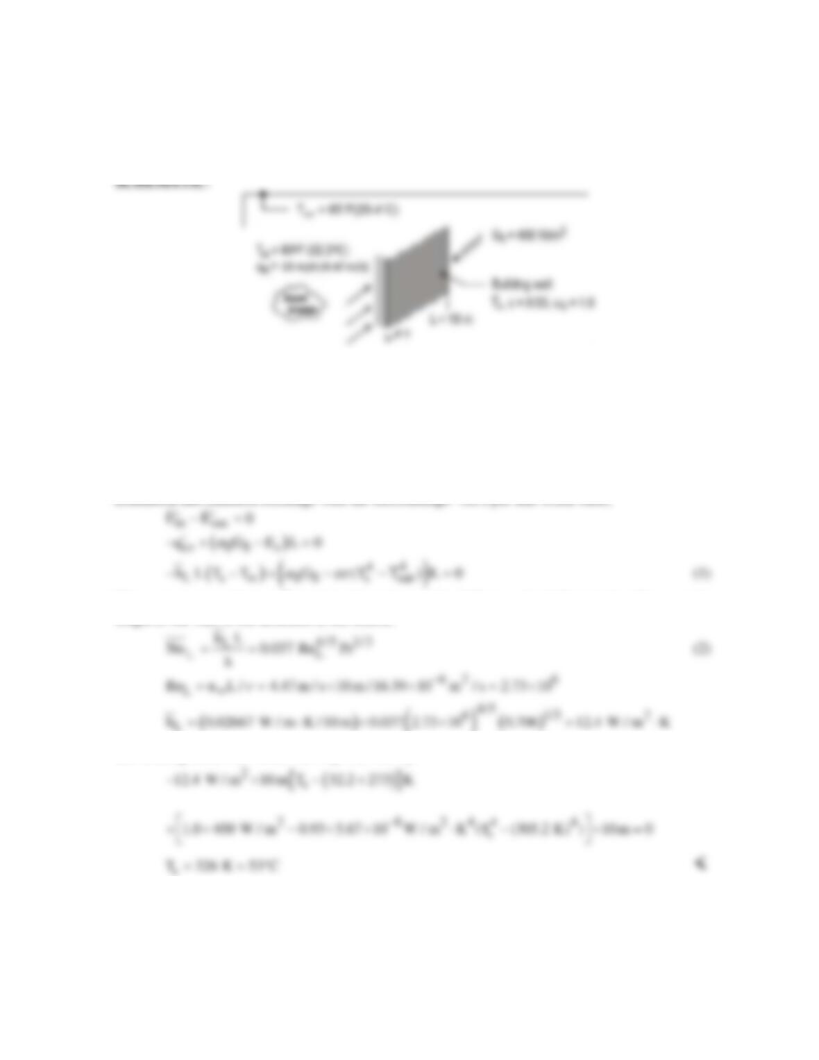
PROBLEM 7.21
KNOWN: Wall of a metal building experiences a 10 mph (4.47 m/s) breeze with air temperature of
90°F (32.2°C), radiation exchange with surrounding at 85°F (29.4°C), and solar insolation of 400
W/m2. The length of the wall in the wind direction is 10 m and the emissivity is 0.93.
FIND: Estimate the average wall temperature.
ASSUMPTIONS: (1) Steady–state conditions, (2) The solar absorptivity of the wall is unity, (3)
Wall is isothermal at the average temperature Ts, (4) Flow is fully turbulent over the wall, (5)
Negligible heat transfer into the building, and (6) large surroundings.
PROPERTIES: Table A-4, Air (assume Tf = 305 K, 1 atm): ν = 16.39 × 10⁻⁶ m2/s, k = 0.02667
W/m⋅K, Pr = 0.706.
ANALYSIS: Perform an energy balance on the wall surface considering convection, absorbed
irradiation and radiation exchange with the surroundings. On a per unit width basis,
The average convection coefficient is estimated using Eq. 7.38 assuming fully turbulent flow over the
length of the wall in the direction of the breeze.
()
L
Substituting numerical values into Eq. (1), find Ts.
COMMENTS: (1) The properties for the correlation should be evaluated at Tf = (Ts + T∞)/2 =
316 K. The assumption of 305 K was reasonable but accuracy could be improved by evaluating
properties at 316 K.
(2) Is the heat transfer by the emission process significant? Would application of a low emissive
coating be effective in reducing the wall temperature, assuming αS remained unchanged? Or, should a
low solar absorbing coating be considered?
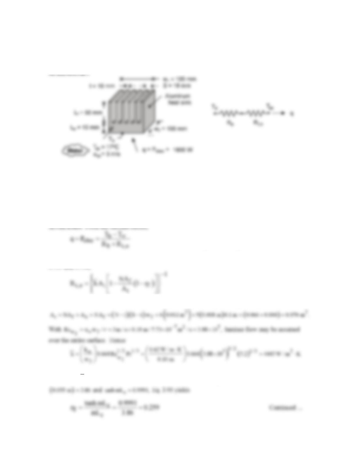
PROBLEM 7.22
KNOWN: Dimensions of aluminum heat sink. Temperature and velocity of coolant (water) flow
through the heat sink. Power dissipation of electronic package attached to the heat sink.
FIND: Base temperature of heat sink.
ASSUMPTIONS: (1) Average convection coefficient associated with flow over fin surfaces may be
approximated as that for a flat plate in parallel flow, (2) All of the electric power is dissipated by the
heat sink, (3) Transition Reynolds number of Rex,c = 5 × 10⁵, (4) Constant properties. (5) Water
temperature is nearly constant as it flows through the array.
PROPERTIES: Given. Aluminum: khs = 180 W/m⋅K. Water: kw = 0.62 W/m⋅K, ν = 7.73 × 10⁻⁷
m2/s, Pr = 5.2.
where
( ) ( )
3
2
b b hs 1 2
R L / k w w 0.01 m /180 W / m K 0.10 m 5.56 10 K / W
−
= ×= ⋅ =×
and, from Eqs.
The fin and total surface area of the array are
( ) ( )
2
f 2f
A 2w L t / 2 0.2 m 0.055 m 0.011 m= += =
and
With
( )
( )
1/ 2
21
1/ 2
hs
m 2h / k t 2 4443 W / m K /180 W / m K 0.01 m 70.3 m ,
−
= = × ⋅ ⋅× =
1
c
mL 70.3 m
−
=
PROBLEM 7.22 (Cont.)
Hence,
1
−
COMMENTS: (1) The boundary layer thickness at the trailing edge of the fin is
( )
2
1/ 2
2w
5w / Re
δ
=
( )
0.80 mm S t .= << −
Hence, the assumption of parallel flow over a flat plate is
reasonable. (2) If a finned heat sink is not employed and heat transfer is simply by convection from
the
22
ww×
base surface, the corresponding convection resistance would be 0.0225 K/W, which is
only twice the resistance associated with the fin array. The small enhancement by the array is
PROBLEM 7.23
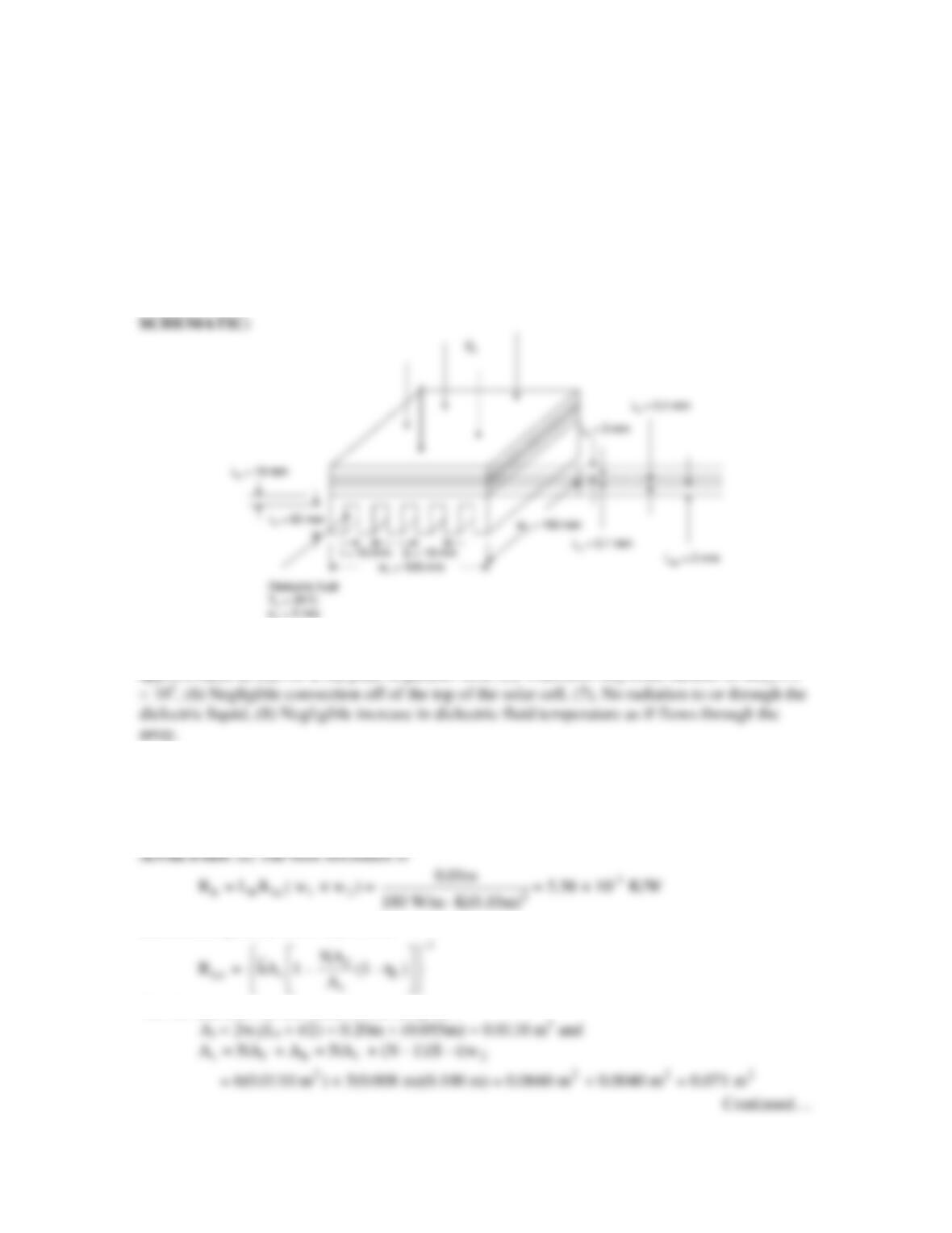
KNOWN: Dimensions of a photovoltaic cell, material and dimensions of a finned heat sink, solar
irradiation and dimensions of concentrating lens, velocity and temperature of dielectric liquid.
FIND: (a) Electric power produced and silicon temperature for a square concentrating lens with
the heat sink in place for Llens = 400 mm, (b) Electric power and silicon temperature with and
without the heat sink for Llens = 1.5 m, (c) Electric power and silicon temperature for 100 mm ≤
Llens ≤ 3000 mm with the heat sink.
∞
∞
ASSUMPTIONS: (1) Steady–state conditions, (2) Constant properties, (3) One-dimensional heat
transfer, (4) Average convection coefficient associated with flow over fin surfaces may be
approximated as that for a flat plate in parallel flow, (5) Transition Reynolds number of Rex,c = 5
PROPERTIES: Given: Aluminum: khs = 180 W/m∙K, Dielectric liquid: kd = 0.064 W/m∙K, ν =
10-6 m2/s,
ρ
= 1400 kg/m3, cp = 1300 J/kg∙K, Pr = 25, Glass: kg = 1.4 W/m∙K, Adhesive: , ka = 145
W/m∙K, Solder: ks = 50 W/m∙K, Aluminum Nitride: kan = 120 W/m∙K.
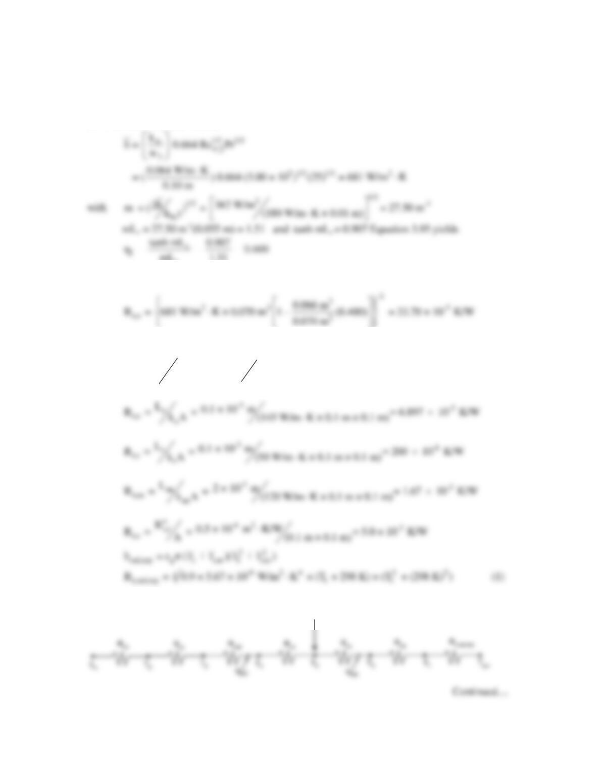
and, from Equations 3.107 and 3.108
The fin and total surface areas of the array are
PROBLEM 7.23 (Cont.)
with
-6 2 5
w2
2
Re = u w /ν = 3 m/s × 0.10 m/10 m /s = 3.00×10 ,
∞
laminar flow may be assumed
over the entire surface. Hence
c
mL 1.51
Hence,
The conduction resistances are
-3
g
t,g g
L3 × 10 m
R = = = 0.2143 K/W
k A (1.4 W/m K × 0.1 m × 0.1 m)⋅
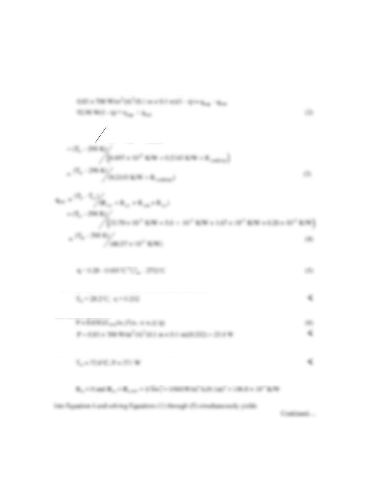
The thermal circuit is
0.83G
c
A(1–η)
0.83G
c
A(1–η)
PROBLEM 7.23 (Cont.)
where Gc = G(Llens/w1)2
From the thermal circuit,
2
lens 1 1 2 top bot
0.83G (L /w ) (w × w )(1 – η) = q + q
3 sur
top t,a t,g t,rad,top
(T – T )
q = (R + R + R )
From the problem statement
Solving Equations (1) through (5) simultaneously yields
The electric power is
(b) Substituting Llens = 1500 mm in Equations 2 and 6 yields
with the heat sink in place. For no heat sink we also substitute
PROBLEM 7.23 (Cont.)
Tsi = 200°C, P = 105 W <
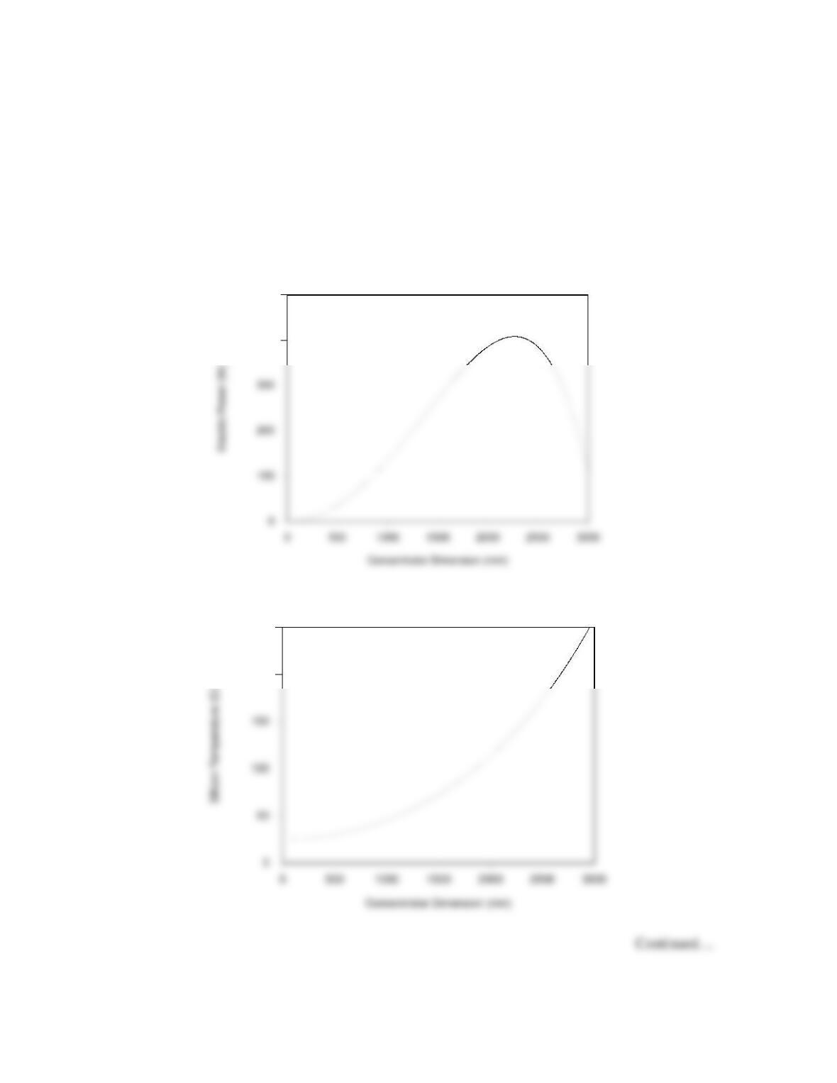
(c) The variation of the silicon temperature and electric power with the heat sink in place is
shown in the accompanying graphs. <
Electric Power vs Concentrator Size
400
500
Silicon Temperature vs Concentrator Size
200
250