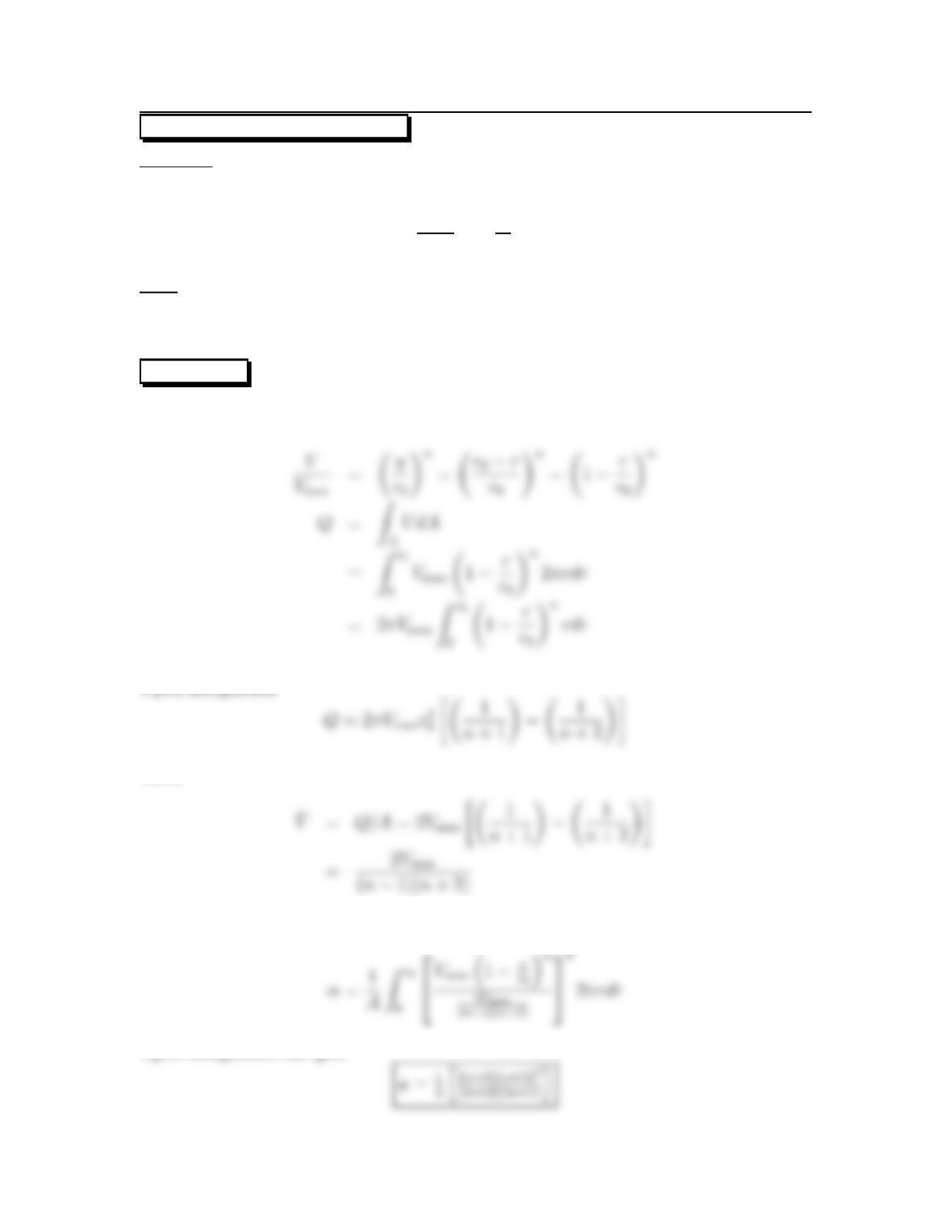
7.17: PROBLEM DEFINITION
Situation:
The velocity distribution in a pipe with turbulent flow is given by
V
Vmax
=µy
r0¶n
Find:
Derive a formula for αas a function of n.
Find αfor n=1/7.
SOLUTION
Flow rate equation
Then
Kinetic energy correction factor
Upon integration one gets
21
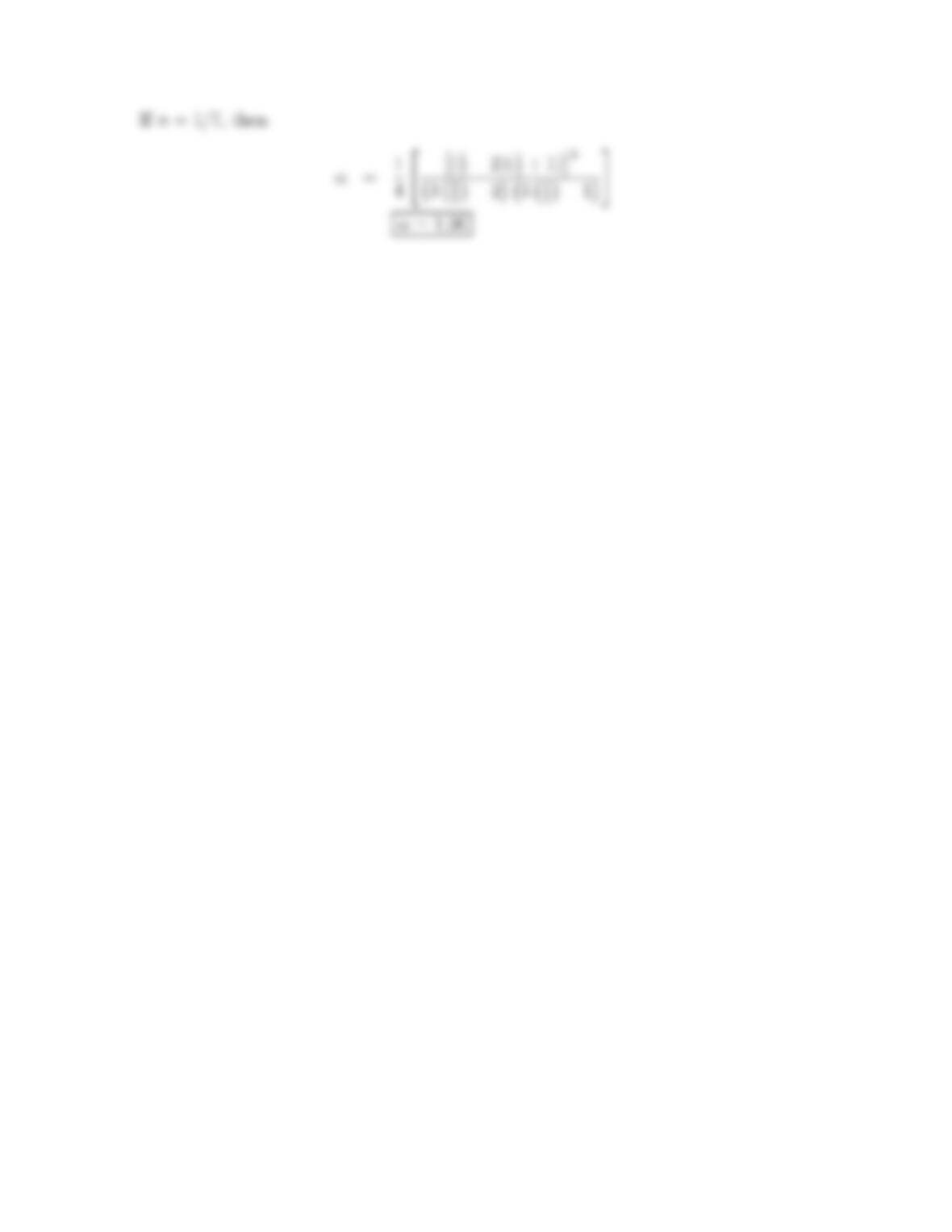
22
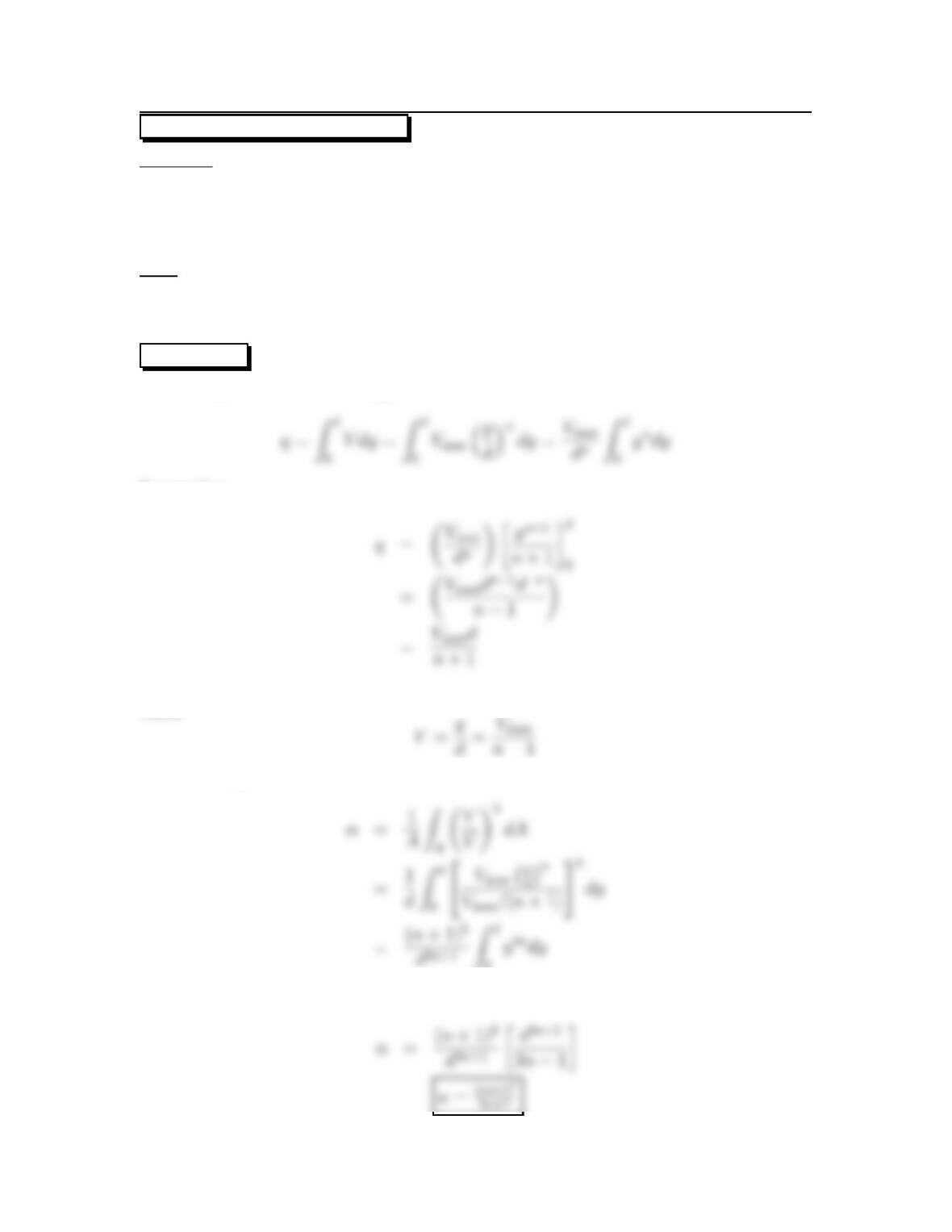
7.18: PROBLEM DEFINITION
Situation:
The velocity distribution in a rectangular channel with turbulent flow is given by
V/Vmax =(y/d)n
Find:
Derive a formula for the kinetic energy correction factor.
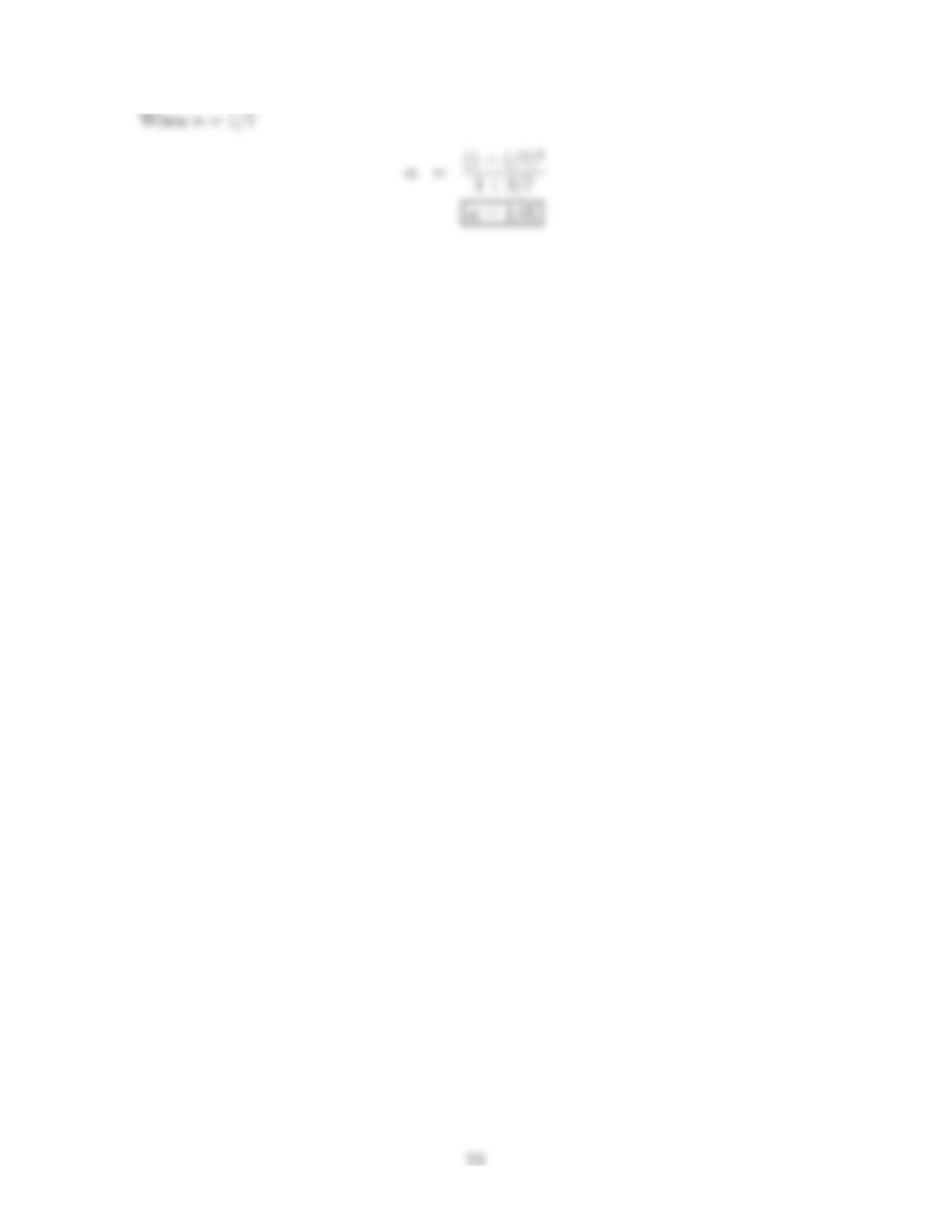
Find αfor n=1/7.
SOLUTION
Solve for qfirst in terms of umax and d
Integrating:
Then
Kinetic energy correction factor
0
Integrating
23
7.19: PROBLEM DEFINITION
Situation:
Turbulent flow in a circular pipe.
r=3.5cm.
Find:
Kinetic energy correction factor: α.
SOLUTION
Kinetic energy correction factor
Theintegralisevaluatedusing
i
Results. The mean velocity is 24.32 m/s and the kinetic energy correction factor is
1.19.
25
Problem 7.20
Answer the questions below.
a. What is the conceptual meaning of the first law of thermodynamics for a system?
•Thelawcanbewrittenfor
b. What is flow work? How is the equation for flow work derived?
•Flow work is work done by forces associated with pressure.
c. What is shaft work? How is shaft work different than flow work?
•Shaft work is any work that is not flow work.
26
Problem 7.21
Answer the questions below.
a. What is head? How is head related to energy? To power?
•Head is a way of characterizing energy or power or work.
b. What is head of a turbine?
•Head of a turbine is a way of describing the work (or power) that is done on
c. How is head of a pump related to power? To energy?
d. What is head loss?
•Conversion of mechanical energy in a flowing fluid to thermal energy via the
27
Problem 7.22
Answer the questions below.
a. What are the five main terms in the energy equation (7.29)? What does each term
mean?
b. How are terms in the energy equation related to energy? To power?
•Each term in the energy equation is a “head term” with units of length. To
c. What assumptions are required to use Eq. (7.29)?
•The flow is steady.
How is the energy equation similar to the Bernoulli equation? List three similarities.
How is the energy equation different from the Bernoulli equation? List three differ-
ences.
Similarities:
•Both equations involve head terms.
28
Problem 7.23
Situation:
Flow in a pipe.
Find:
Prove that fluid in a constant diameter pipe will flow from a location with high
piezometric head to a location with low piezometric head.
Assumptions:
No pumps or turbines in the pipeline.
Steady flow.
SOLUTION
The energy equation (7.29).
Term-by-term analysis:
Energy equation (simplified form):
29
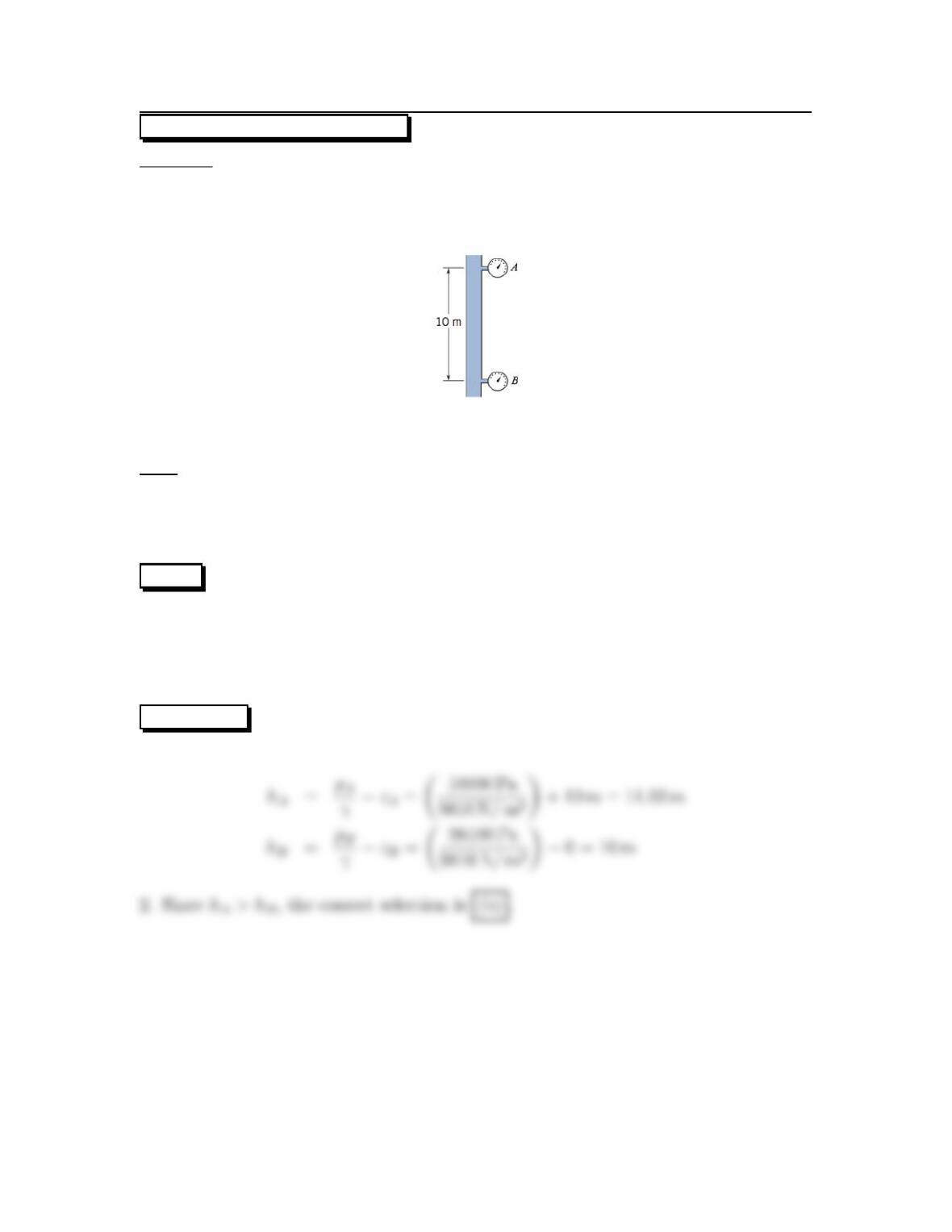
7.24: PROBLEM DEFINITION
Situation:
Water flows in a vertical pipe.
L=10m,pA=10kPa.
pB=98.1kPa.
Find: Direction of flow in a pipe:
(a) Upward.
(b) Downward.
(c) No flow.
PLAN
1. Calculate the piezometric head hat A and B.,
2. To determine flow direction, compare the piezometric head values.
Whichever location has the larger value of his upstream.
If the hvalues are the same, there is no flow.
SOLUTION
1. Piezometric head:
30
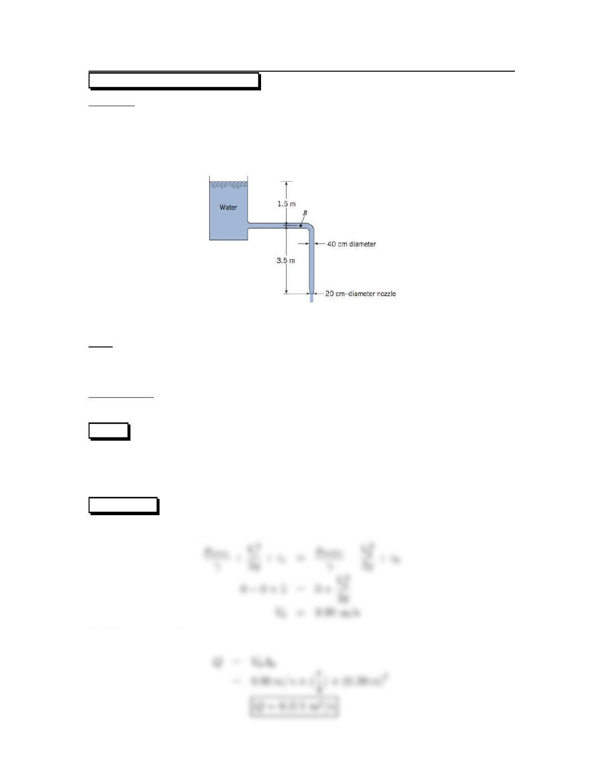
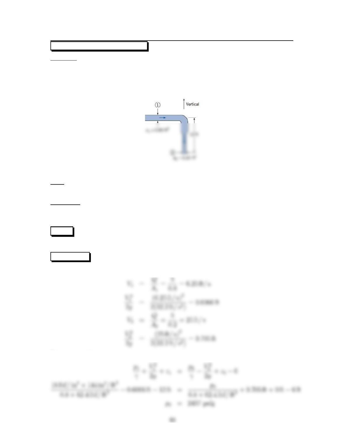
7.25: PROBLEM DEFINITION
Situation:
Water flowing from a tank into a pipe connected to a nozzle.
α=1.0,DB=40cm.
D0=20cm,z0=0m.
zB=3.5m,zr=5m.
Find:
(a) Discharge in pipe (m3/s).
(b) Pressure at point B (kPa).
Assumptions:
γ=9810N/m3.
PLAN
1. Find velocity at nozzle by applying the energy equation.
2. Find discharge by applying Q=AoVo
3. Find the pressure by applying the energy equation.
SOLUTION
1. Energy equation (point 1 on reservoir surface, point 2 at outlet)
2. Flow rate equation
31
3. Energy equation (point 1 on reservoir surface, point 2 at B)
32
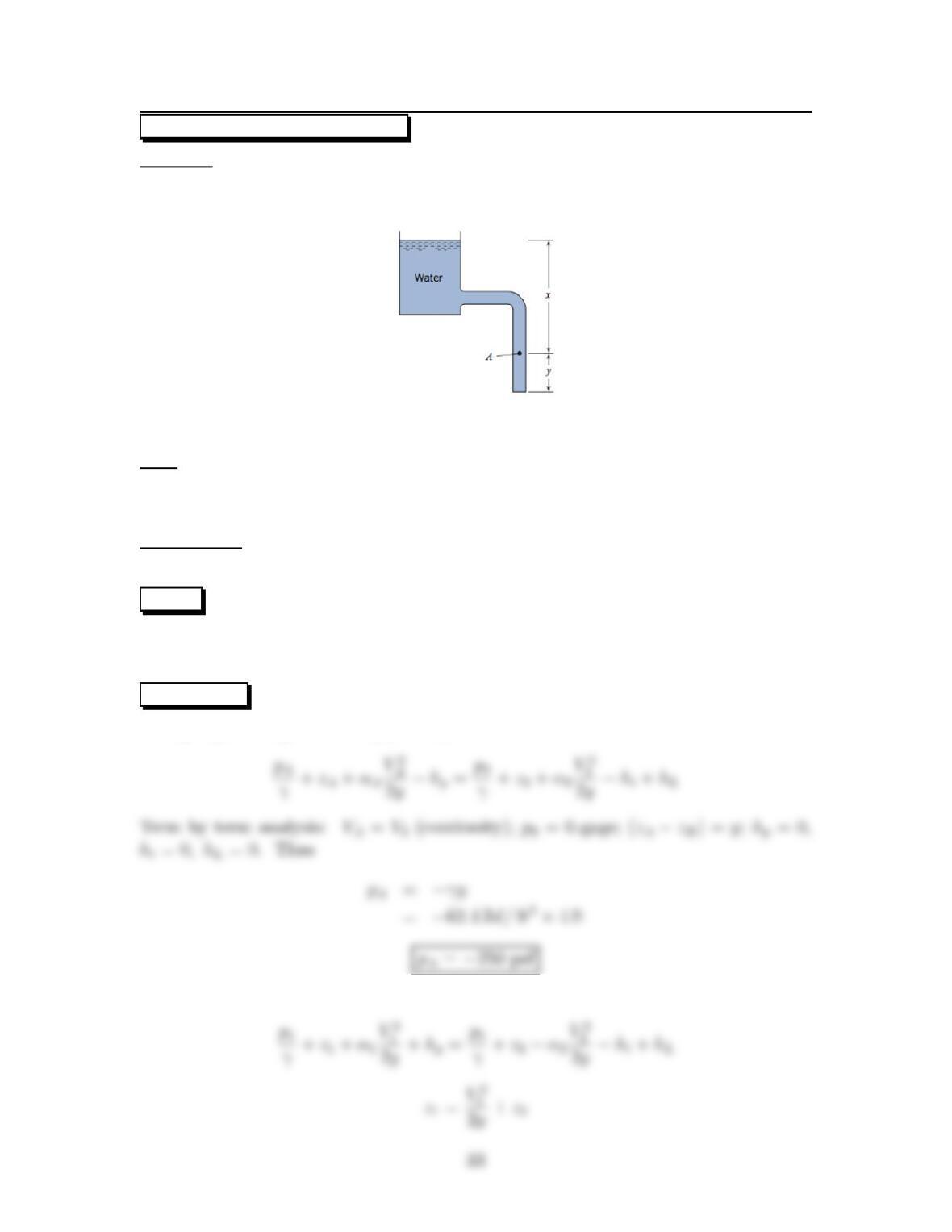
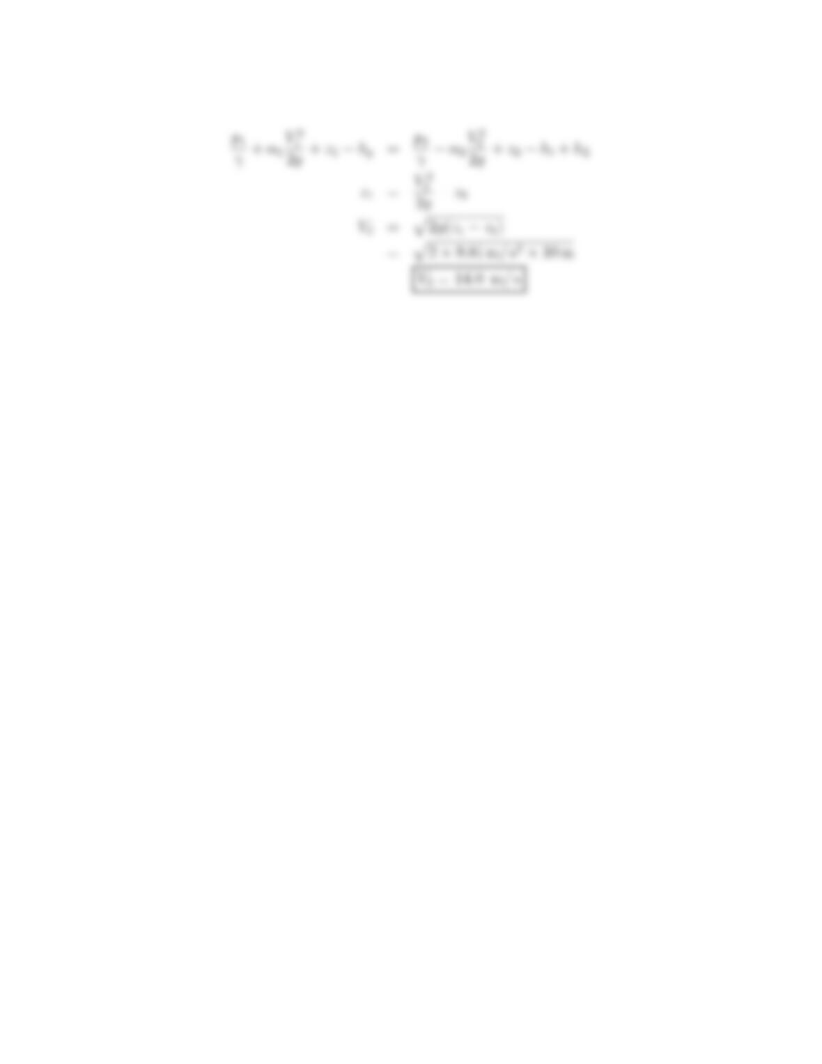
7.26: PROBLEM DEFINITION
Situation:
Water drains from a tank into a pipe.
x=14ft,y=4ft.
Find:
Pressure at point A(psf).
Velocity at exit (ft/s).
Assumptions:
α2=1
PLAN
To find pressure at point A, apply the energy equation between point A and the pipe
exit. Then, then apply energy equation between top of tank and the exit.
SOLUTION
Energy equation (point A to pipe exit).
Energy equation (1= top of tank; 2 = pipe exit)
Solve for velocity at exit
34
7.27: PROBLEM DEFINITION
Situation:
Water drains from a tank into a pipe.
x=6m,y=4m.
Find:
Pressure at point A(kPa).
Velocity at exit (m/s).
Assumptions:
α1=1.
PLAN
1. Find pressure at point A by applying the energy equation between point A and
thepipeexit.
2. Find velocity at the exit by applying the energy equation between top of tank and
the exit.
SOLUTION
1. Energy equation (section A to exit plane):
35
2. Energy equation (top of tank to exit plane):
36
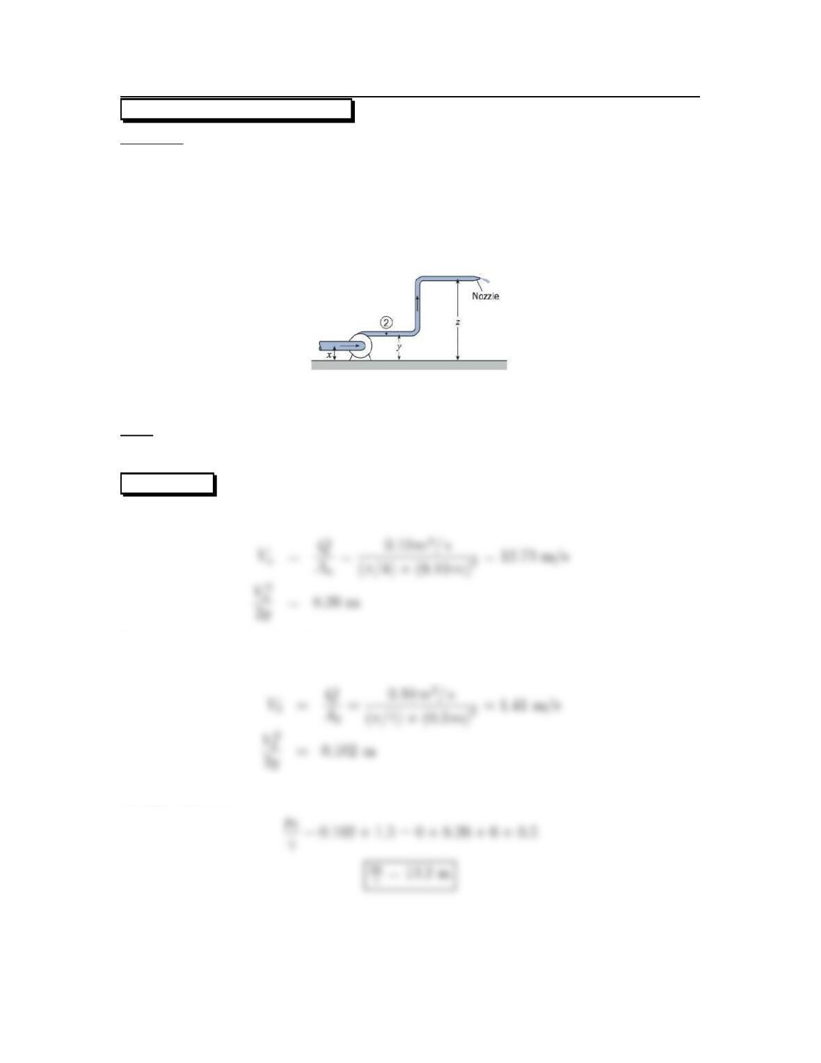
7.28: PROBLEM DEFINITION
Situation:
Water is pushed out a nozzle by a pump.
Q=0.1m
3/s,D2=30cm.
Dn=10cm,zn=6m.
hL=0.5m.
x=1m,y=1.5m.
Find:
Pressure head at point 2.
SOLUTION
Flow rate equation to find Vn(velocity at nozzle)
Flow rate equation to find V2
Energy equation
37
Problem 7.29
Q=3.5ft
x=1ft, y=3ft, z=10ft
Assume a head loss of 1 ft is derived over the distance from point 2 to the jet.
Jet from the nozzle is 1-in in diameter.
Assume α=1.0 throughout.
Find:
Pressure at point 2.
PLAN
Use flow rate equation and energy equation.
SOLUTION
Flow rate equation to find Vn(velocity at nozzle)
Flow rate equation to find V2
Energy equation
38
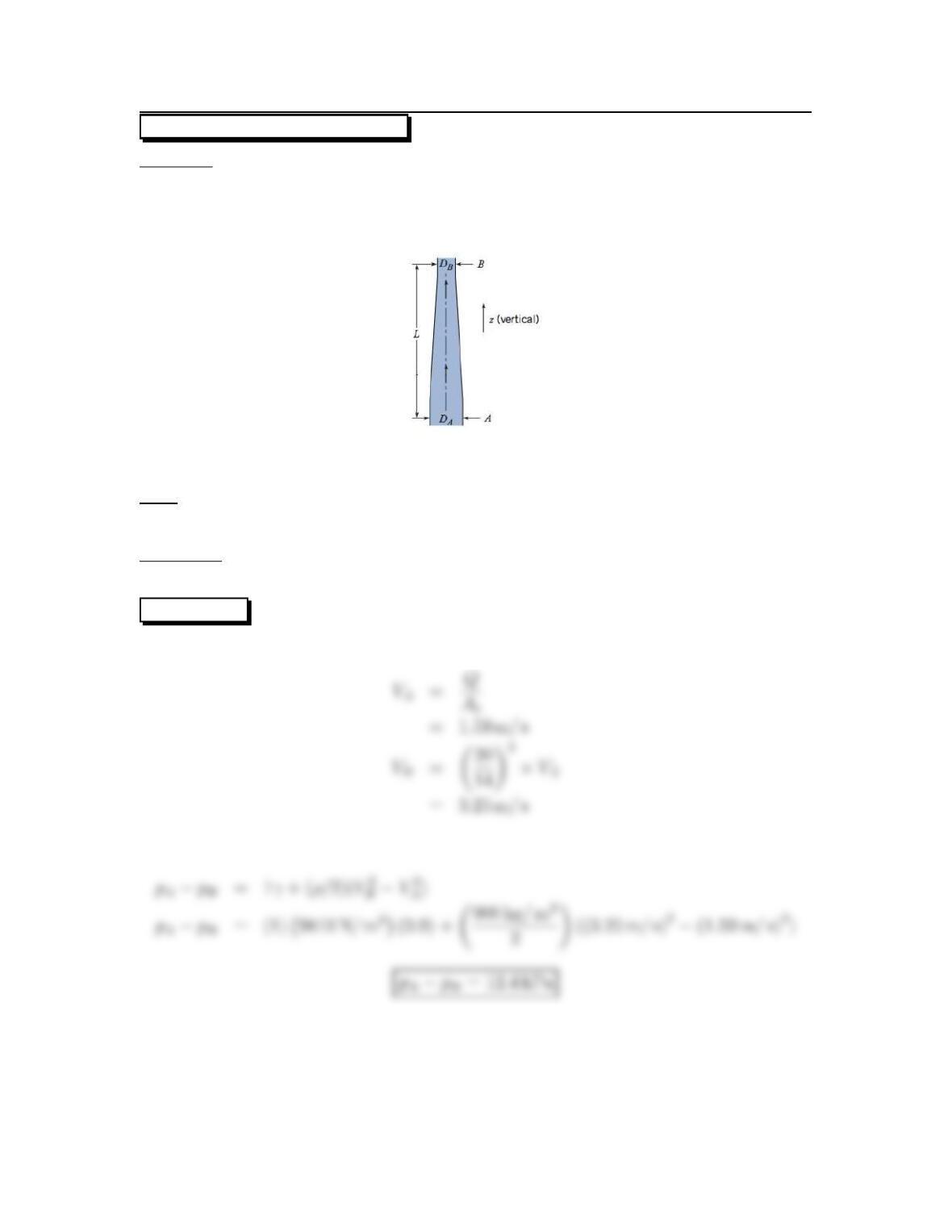
7.30: PROBLEM DEFINITION
Situation:
Oil moves through a narrowing section of pipe.
DA=20cm,DB=14cm.
L=1m,Q=0.05 m3/s.
Find:
Pressure difference between Aand B.
Properties:
S=0.90.
SOLUTION
Flow rate equation
Energy equation
39
7.31: PROBLEM DEFINITION
Situation:
Gasoline flows in a pipe that narrows into a smaller pipe.
Q=5ft
3/s,p1=18psig.
hL=6ft,∆z=12ft.
A1=0.8ft
2,A2=0.2ft
2.
Find:
Pressure at section 2 (psig).
Properties:
Gasoline, S=0.8.
Water, Table A.5: γ=62.4lbf/ft3.
PLAN
Apply flow rate equation and then the energy equation.
SOLUTION
Flow rate equation:
Energy equation: