1
CHAPTER 7
Problem 7.1
The lateral force–deformation relation of the system of
Example 6.3 is idealized as elastic–perfectly plastic. In
the linear elastic range of vibration this SDF system has
the following properties: lateral stiffness, k = 2.112
kips/in., and ζ = 2%. The yield strength fy = 5.55 kips and
the lumped weight w = 5200 lb.
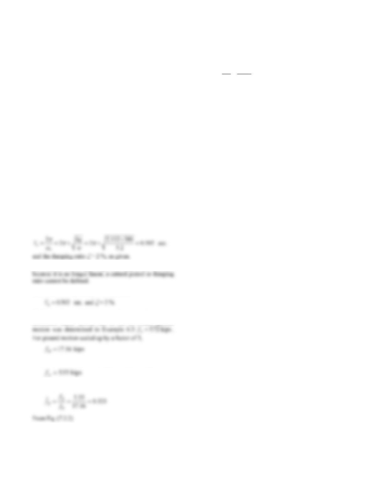
(a) Determine the natural period and damping ratio of this
system vibrating at amplitudes smaller than uy.
(b) Can these properties be defined for motions at larger
amplitudes? Explain your answer.
(c) Determine the natural period and damping ratio of the
corresponding linear system.
(d) Determine ̅y and Ry for this system subjected to El
Centro ground motion scaled up by a factor of 3.
Solution:
(a) For vibration amplitudes smaller than uy, the system is
vibrating in the linear elastic range. The period of these
oscillations is
(b) A system vibrating at amplitudes larger than uy yields;
(c) For the corresponding linear system,
(d) The peak value fo of the equivalent static force for the
associated linear system due to the El Centro ground
The yield strength of the elastoplastic system is given:
From Eq. (7.2.1)
09.3
55.5
16.17
y
o
yf
f
R
2
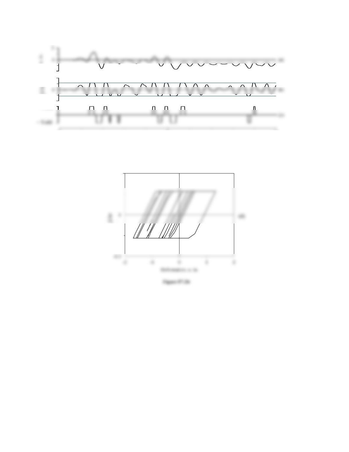
Determine by the central difference method the deforma–
tion response u(t) for 0 < t < 10 sec of an elastoplastic
undamped SDF system with Tn = 0.5 sec and fy = 0.125 to
El Centro ground motion. Reproduce Fig. 7.4.2, showing
the force–deformation relation in part (d) for the entire
duration.
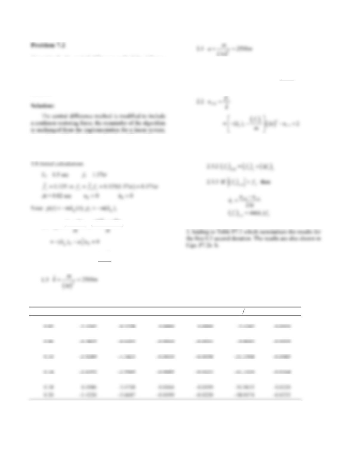
An outline of the algorithm is listed as follows (for zero
damping):
Steps
1.1
upku
mu ku
g
0
00 00
1.2
uu tu tu
10 0
2
0
20
2.0 Calculations for each time step.
2.1
i
i
siigi u
t
m
fauump 2
1
2
)(
ˆ
2.3 Determine restoring force at time step i+1.
2.3.1
fkuu
siii
1
Computational steps 2.1–2.3.3 are repeated for i = 0, 1, 2,
Table P7.2 Numerical solution by Central Difference Method for the first 0.2 seconds
ti p
i/m (fs)i/w ui–1 u
i
pm
i ui+1
0.00 0 0.0000 0.0000 0.0000 0.0000 0.0000
0.04 –1.4065 –0.3867 0.0000 –0.0010 –6.1214 –0.0024
0.08 –1.6538 –0.9173 –0.0024 –0.0039 –14.5217 –0.0058
0.12 –4.2002 –1.9479 –0.0058 –0.0085 –30.8377 –0.0123
0.16 –1.0703 –3.1494 –0.0123 –0.0164 –49.8598 –0.0199
3
0510
-2
0.3
-0.3
Time, sec
+ Yield
0.3
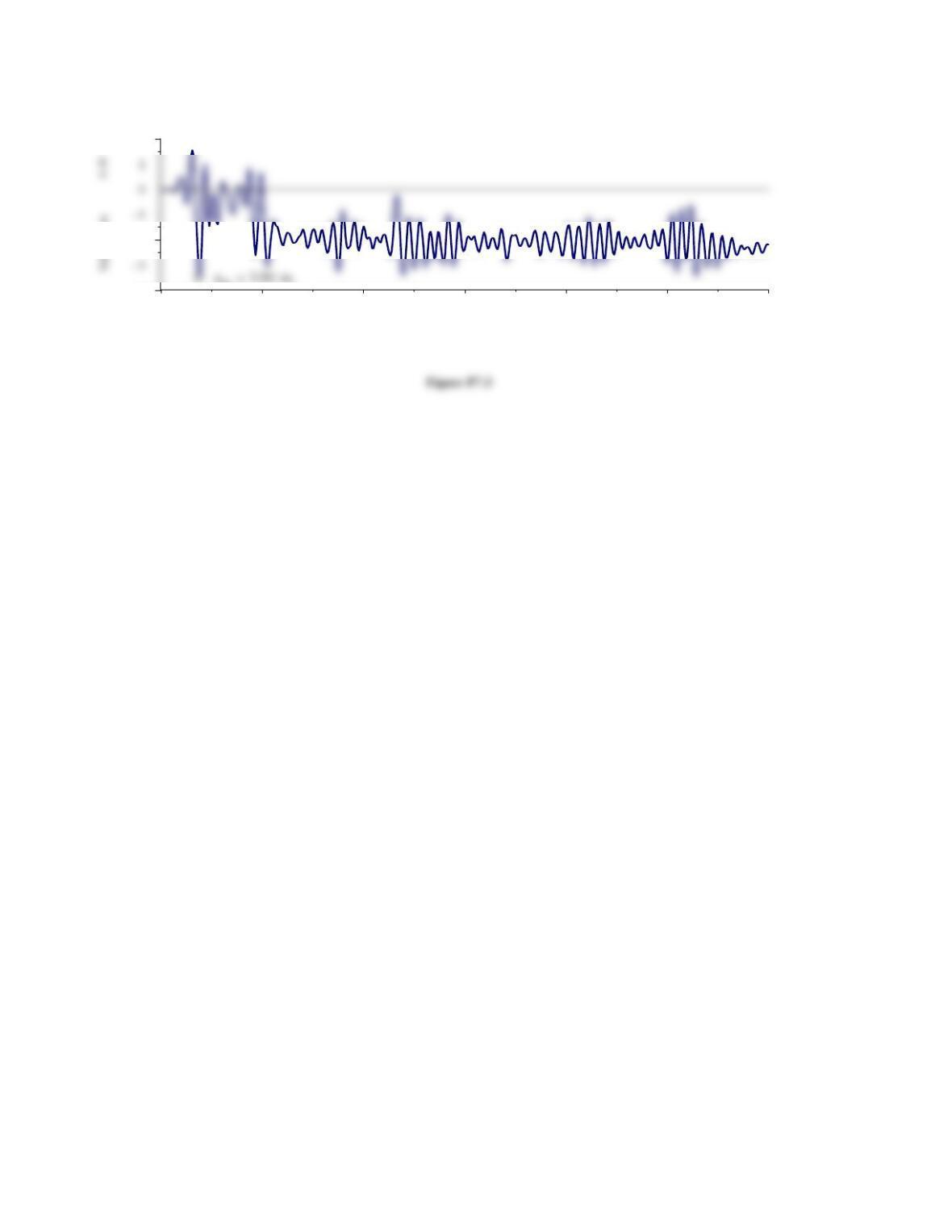
Figure P7.2a
4
Problem 7.3
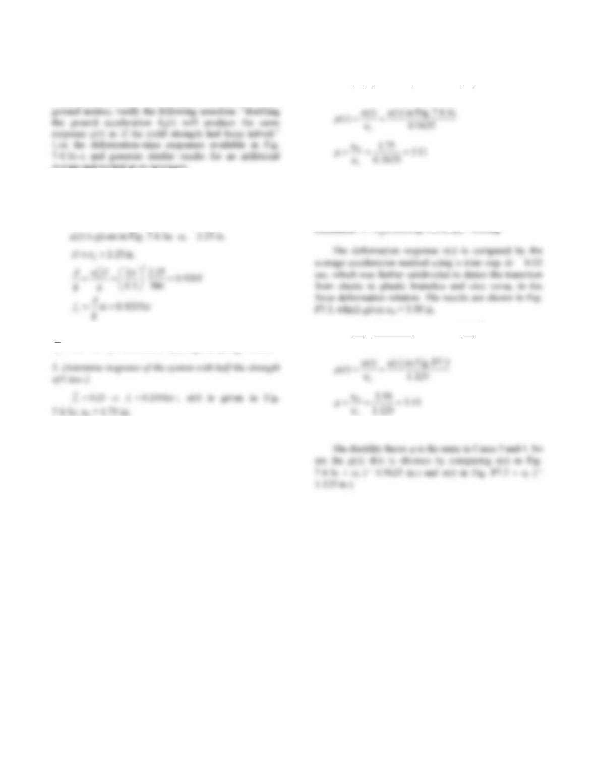
For a system with Tn = 0.5 sec and ζ = 5% and El Centro
system and excitation as necessary.
Solution:
1. Determine response of the corresponding linear
system.
2. Determine response of the elastoplastic system with
0.5 0.4602
yy
ff w; u(t) is given in Fig. 7.4.3b.
2
0.2301 g 0.2301g 0.5625 in.
2
yn
y
fmT
ukk
4. Determine response of the system of Case 2 to double
the El Centro ground motion.
Tn = 0.5 sec,
= 5%, fy = 0.4602 w
()ut
2
0.4602 g 0.4602g 1.125 in.
2
yn
y
fmT
ukk
5. Verification.
5
0 5 10 15 20 25 30
-4
-2
2
T im e , se c
6
For a system with Tn = 0.5 sec and ζ = 5% and El Centro
ground motion, show that for fy = 0.25 the ductility factor
1. Determine response of the corresponding linear
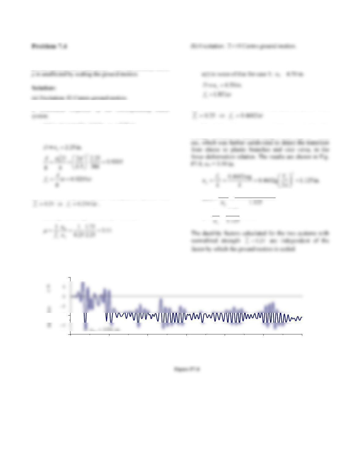
u(t) is given in Fig. 7.4.3a; uo = 2.25 in.
2. Determine response of the elastoplastic system with
u(t) is given in Fig. 7.4.3c, um = 1.75 in.
3. Determine response of the corresponding linear
system.
4. Determine response of the elastoplastic system with
The deformation response u(t) is computed by the
average acceleration method using a time step t = 0.02
11.3
50.3
P7.15 Fig.in )()(
)(
m
u
tu
tu
t
0 5 10 15 20 25 30
-4
-2
2
T im e , se c
Fig. P7.15
7
Problem 7.5
From the response results presented in Fig. 7.4.3, compute
the ductility demands for ̅y = 0.5, 0.25, and 0.125.
Solution:
(a) For fy05., from Fig. 7.4.3, 1.62 in.
m
u, and
8
Problem 7.6
For the design earthquake at a site, the peak values of
ground acceleration, velocity, and displacement have been
Solution:
T
b’-c’: Ay(. ) .1 83 2 1 0 818gg
4. The ordinate for point f’ is Dy18
6in.
Join
T
6. Draw the line Ay050.g
for
T
n1 33sec.
(d) Determine Ta, ‘b
T, Tc, Td, Te, and Tf.
(e) Determine equations for A
T
yn
()g
.
133 18sec sec
Tn: Find equation to the
straight line on log-log paper connecting points a’
and b’:
AT TT
g
10 33sec sec
T
n
T
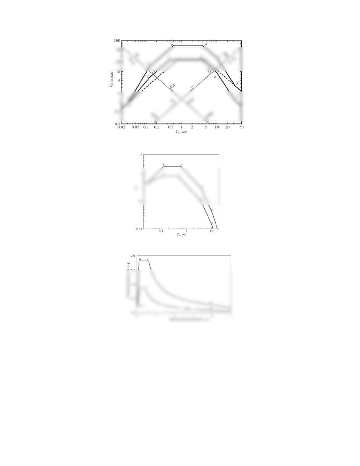
9
Figure P7.6a
Figure P7.6b
Figure P7.6c
10
Consider a vertical cantilever tower that supports a lumped
weight w at the top; assume that the tower mass is negli–
gible, ζ = 5%, and that the force–deformation relation is
elastoplastic. The design earthquake has a peak
acceleration of 0.5g, and its elastic design spectrum is
given by Fig. 6.9.5 multiplied by 0.5. For three different
values of the natural vibration period in the linearly elastic
range, Tn = 0.02, 0.2, and 2 sec, determine the lateral
remain elastic, and (ii) the allowable ductility factor is 2, 4,
or 8. Comment on how the design deformation and design
force are affected by structural yielding.
Solution:
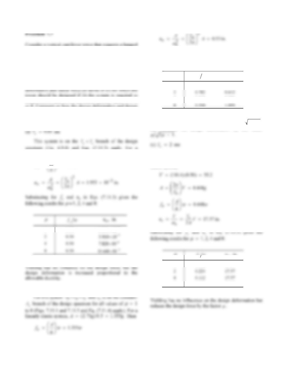
spectrum (Fig. 6.9.4) and Eqs. (7.11.3) apply. For a
linearly elastic system,
A
(). .1050 05gg
. Then
0.5
f
o
A
f
ww
1 0.50 1 955 10 3
.
(b) 0.2
n
T sec
n
Substituting for
f
o and uo in Eq. (7.11.3) gives the
following results for
1, 2, 4, and 8:
w
y
f um,i
n
.
1 1.355 0.530
4 0.512 0.801
Yielding reduces the design force by the factor of 21
,
but increases the design deformation by the factor
This system is on the
T
T
nc
part of the design
spectrum (Fig. 6.9.4) and Eq. (7.11.5) apply. For a linearly
elastic system,
w
y
f um,in.
1 0.448 17.57
8 0.056 17.57
11
Problem 7.8
Consider a vertical cantilever tower with lumped weight w,
Tn = 2 sec, and fy = 0.112w. Assume that ζ = 5% and
elastoplastic force–deformation behavior. Determine the
lateral deformation for the elastic design spectrum of Fig.
6.9.5 scaled to a peak ground acceleration of 0.5g.
Solution:
For a system with 2sec
n
T, Fig. 6.9.5 gives
and Eq. (7.12.2) leads to
Knowing Ry,
can be computed from Eq. (7.11.2) for
2sec
n
T:
Problem 7.9
Solve Example 7.3 for an identical structure except for one
change: The bents are 13 ft high.
Solution:
For transverse ground motion the viaduct can be ideal-
3
EI
k (a)
load is given by
where Ig is the second moment of area of the gross cross–
section, Ec and Es are the elastic moduli of concrete and
The mass of the idealized SDF system is the tributary
mass for one bent, i.e., the mass of 130 ft length of the
superstructure:
2. The plastic rotation acceptable at the base of the column
is 02.0
p
radians.
3. The design displacement given by Eq. (7.12.5) is
pym huu
0.78 + 156 0.02 = 3.90 in.
and the design ductility factor is
4. The deformation design spectrum for inelastic systems is
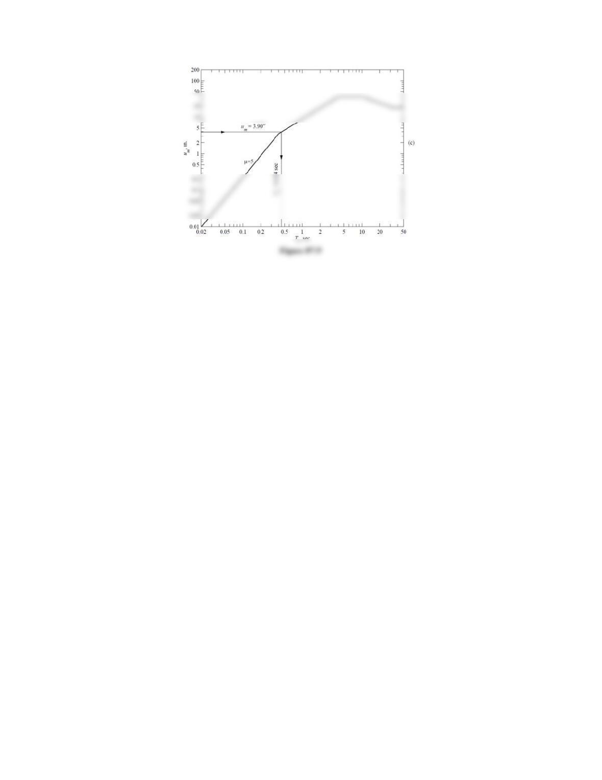
shown in Fig. P7.9 for 5
. Corresponding to um = 3.9
5. The yield strength is given by Eq. (7.12.7):
for axial force due to dead load of 1690 kips due to the
superstructure plus 55 kips, due to self-weight of the
column and the bending moment due to lateral force = fy:
7. Since the yield deformation computed in Step 6 differs
significantly from the initial estimate of 0.78 in.
y
u
,
Table P7.9
No. y
u m
u
n
T k y
f t
Design y
f Design k y
u
(in.) (in.) (secs) (kips/in.) (kips) (%) (kips) (kips/in.) (in.)
2 0.62 3.74 6.00 0.426 953.0 594.9 2.80 664.6 1046.5 0.64
13