PROBLEM 7.81
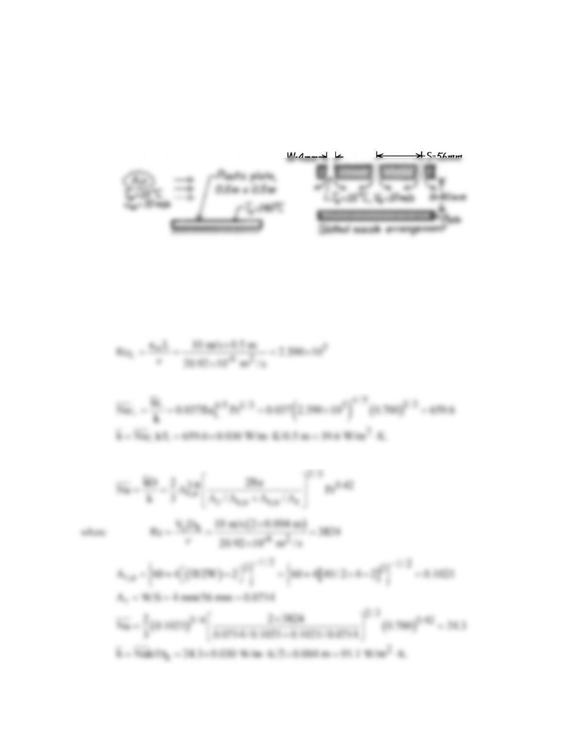
KNOWN: Air at 10 m/s and 15°C is available for cooling hot plastic plate. An array of slotted
nozzles with prescribed width, pitch and nozzle-to–plate separation.
FIND: (a) Improvement in cooling rate achieved using the slotted nozzle arrangement in place of
turbulent air in parallel flow over the plate, (b) Change in heat rates if air velocities were doubled, (c)
Air mass rate requirement for the slotted nozzle arrangement.
SCHEMATIC:
ASSUMPTIONS: (1) Steady-state conditions, (2) For parallel flow over plate, flow is turbulent, (3)
Negligible radiation effects.
PROPERTIES: Table A-4, Air (Tf = (140 + 15)°C/2 = 350 K, 1 atm): r = 0.995 kg/m3, ν = 20.92 ×
10-6 m2/s, k = 30.3 × 10⁻³ W/m⋅K, Pr = 0.700.
ANALYSIS: (a) For turbulent flow over the plate of length L with
using the turbulent flow correlation, find
For an array of slot nozzles,
Continued …
PROBLEM 7.81 (Cont.)
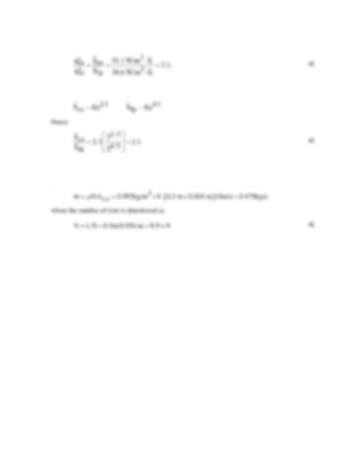
The improvement in heat rate with the slot nozzles (sn) over the flat plate (fp) is
(b) If the air velocities were doubled for each arrangement in part (a), the heat transfer coefficients are
affected as
That is, comparative advantage of the slot nozzle over the flat plate decreases with increasing
velocity.
(c) The mass rate of air flow through the array of slot nozzles is
COMMENTS: Note, for the slot nozzle, the hydraulic diameter is Dh = 2W and the relative nozzle
area (Ac,e/Acell) is Ar = W/S.
PROBLEM 7.82
KNOWN: Air jet velocity and temperature of 10 m/s and 15°C, respectively, for cooling hot plastic
plate..
FIND: Design of optimal round nozzle array. Compare cooling rate with results for a slot nozzle
array and flow over a flat plate. Discuss features associated with these three methods relevant to
selecting one for this application.
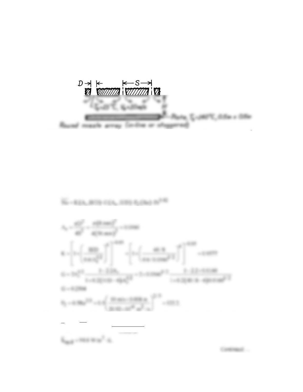
SCHEMATIC:
ASSUMPTIONS: (1) Steady-state conditions, (2) Negligible radiation effects.
PROPERTIES: Table A-4, Air (Tf = (140 + 15)°C/2 = 350 K, 1 atm): r = 0.995 kg/m3, ν = 20.92 ×
10-6 m2/s, k = 30.0 × 10⁻³ W/m⋅K, Pr = 0.700.
ANALYSIS: To design an optimal array of round nozzles, we require that Dh,op ≈ 0.2H and Sop ≈
1.4H. Choose H = 40 mm, the nozzle-to–plate separation, hence
h,op op
D D 0.2 40 mm 8 mm S 1.4 40 mm 56 mm.==×= =×=
For an array of round nozzles,
where for an in–line array, see Fig. 7.18,
The average heat transfer coefficient for the optimal in–line (op, il) array of round nozzles is,
( )
0.42
op,il h,op
0.030 W/m K
h Nu k/D 0.9577 0.2504 122.2 0.700
⋅
= = ×××
PROBLEM 7.82 (Cont.)
If an optimal staggered (op,s) array were used, see Fig. 7.18, with
Using the previous results for parallel flow (pf) and the slot nozzle (sn) array, the heat rates, which are
proportional to the average convection coefficients, can be compared.
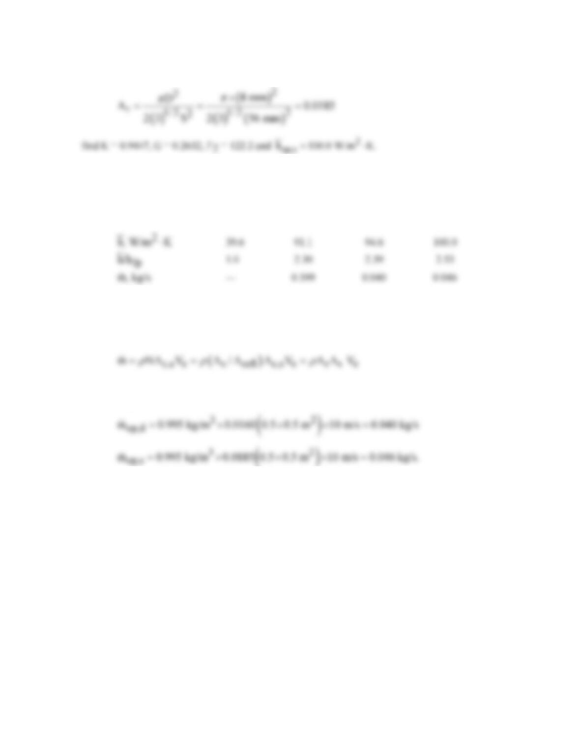
Arrangement Flat plate Slot nozzle Optimal round nozzle (op)
(fp) (sn) In–line (il) Staggered (s)
For these flow conditions, we conclude that there is only slightly improved performance associated
with using the round nozzles. As expected, the staggered array is better than the in–line arrangement,
since the former has a higher area ratio (Ar). The air flow requirements for the round nozzle arrays
are
where N = As/Acell is the number of nozzles and As is the area of the plate to be cooled.
Substituting numerical values, find
For this application, selection of a nozzle arrangement should be based upon air flow requirements
(round nozzles have considerable advantage) and costs associated with fabrication of the arrays (slot
nozzle may be easier to form from sheet metal).

PROBLEM 7.83
KNOWN: A round nozzle with a diameter of 1 mm located a distance of 2 mm from the surface
mount area with a diameter of 2.5 mm; air jet has a velocity of 70 m/s and a temperature of 500°C.
FIND: (a) Estimate the average convection coefficient over the area of the surface mount, (b)
Estimate the time required for the surface mount region on the PCB, modeled as a semi–infinite
SCHEMATIC:
ASSUMPTIONS: (1) Air jet is a single round nozzle, (2) Uniform temperature over the PCB surface,
and (3) Surface mount region can be modeled as a one-dimensional semiinfinite medium.
PROPERTIES: Table A-4, Air (Tf = 536 K, 1 atm): ν = 4.36 × 10⁻⁵ m2/s, k = .0497 W/m⋅K, Pr =
ANALYSIS: For a single round nozzle, from the correlation of Eqs. 7.71 and 7.72, estimate the
convection coefficient,
( )
1
0.42
Nu r H hD
G , F Re Nu
DD k
Pr
= =
(1,2)
where
The Reynolds number is based on the jet diameter and velocity at the nozzle,
and ro is the radius of the region over which the average coefficient is being evaluated. The
thermophysical properties are evaluated at the film temperature, Tf = (Te + Ti)/2. The results of the
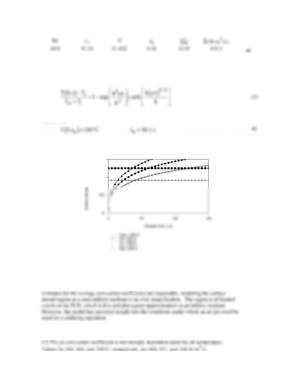
calculation are tabulated below.
Continued …
H = 2 mm
D = 1 mm
5
H = 2 mm
D = 1 mm
5
PROBLEM 7.83 (Cont.)
<
Consider the surface mount region as a semi–infinite medium, with solder properties, initially at a
uniform temperature of 25°C, that experiences sudden exposure to the convection process with the air
jet at a temperature T∞ = 500°C and the convection coefficient as found in part (a). The surface
temperature, T(0,t), is determined from Case 3, Fig. 5.7 and Eq. 5.63,
where α = k/rcp. With Ti = 25°C and T∞ = Te, by trial-and-error, or by using the appropriate IHT
model, find
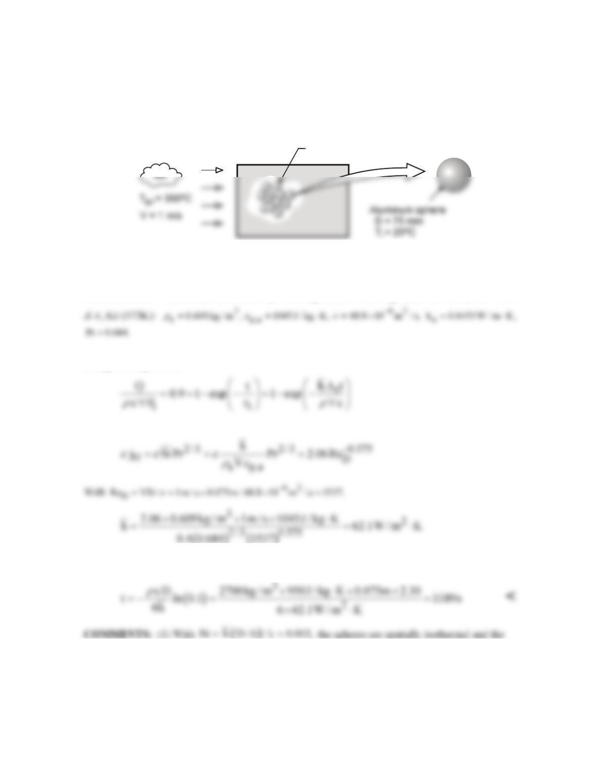
(c) Using the foregoing relations in IHT, the surface temperature T(0,t) is calculated and plotted for jet
air temperatures of 400, 500 and 600°C for 0 ≤ t ≤ 40 s.
200
300
The effect of increasing the jet air temperature is to reduce the time for the surface
temperature to reach the solder temperature of 183°C. With the 700°C air jet, it takes about
14 s to reach the solder temperature, and the glass transition temperature is achieved in 35 s.
The analysis represents a first–order model giving approximate results only. While the
COMMENTS: (1) Note that for our application, the round nozzle correlation of part (a)
exceeds the ranges of validity.
PROBLEM 7.84
KNOWN: Diameter and properties of aluminum spheres used in packed bed. Porosity of bed and
velocity and temperature of inlet air.
FIND: Time for sphere to acquire 90% of maximum possible thermal energy.
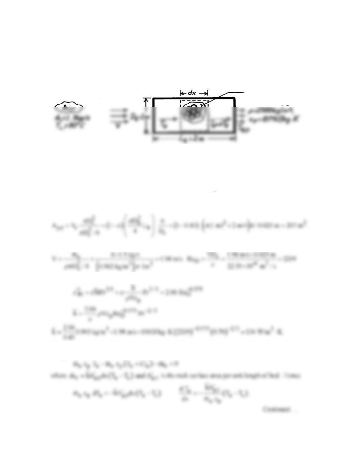
SCHEMATIC:
Packed bed,
e
= 0.40
ASSUMPTIONS: (1) Negligible heat transfer to or from a sphere by radiation or conduction due to
contact with other spheres, (2) Validity of lumped capacitance method, (3) Constant properties.
PROPERTIES: Prescribed, Aluminum:
3
2700 kg / m , c 950 J / kg K, k 240 W / m K.
r
= = ⋅= ⋅
Table
ANALYSIS: From Eqs. 5.7 and 5.8a, achievement of 90% of the maximum possible thermal energy
storage corresponds to
where the convection coefficient is given by
Hence, with
s
A / 6 / D,∀=
lumped capacitance approximation is excellent. (2) Before the packed bed becomes fully charged, the
temperature of the air decreases as it passes through the bed. Hence, the time required for a sphere to
reach a prescribed state of thermal energy storage increases with increasing distance from the bed
inlet.
PROBLEM 7.85
KNOWN: Overall dimensions of a packed bed of rocks. Rock diameter and thermophysical
properties. Initial temperature of rock and bed porosity. Flow rate and upstream temperature of
atmospheric air passing through the pile.
FIND: Rate of heat transfer to pile.
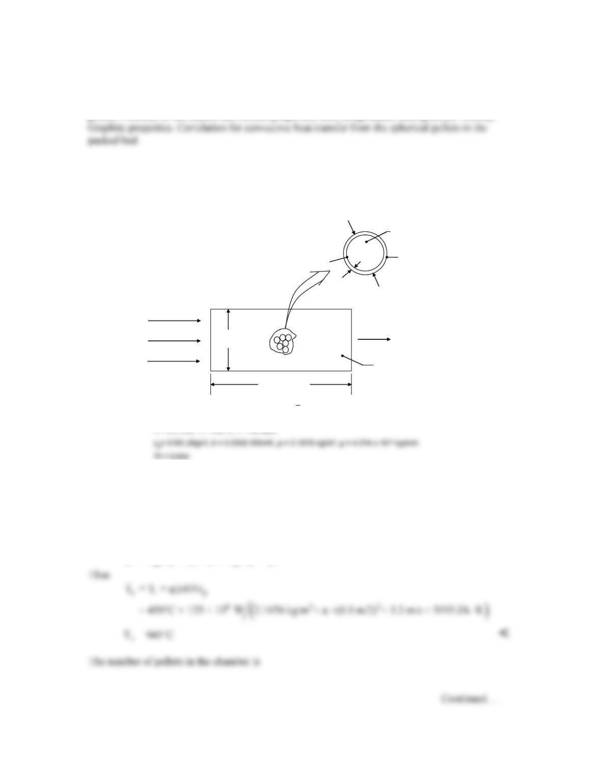
SCHEMATIC:
Rocks, ε= 0. 45
D
T
= 0. 025m, T
s
=25° C
ASSUMPTIONS: (1) Rocks are spherical and at a uniform temperature, (2) Steady-state conditions.
PROPERTIES: Table A-4, Atmospheric air (T∞ = 363K): ν = 22.35 × 10⁻⁶ m2/s, k = 0.031 W/m⋅K,
Pr = 0.70, r = 0.963 kg/m3, cp = 1010 J/kg⋅K.
ANALYSIS: The heat transfer rate may be expressed as
p,t m
q hA T= ∆
where the total surface area
of the rocks is
The upstream velocity and Reynolds number are
From Section 7.8, it follows that
The appropriate form of the mean temperature difference,
m
T,∆
may be obtained by performing an
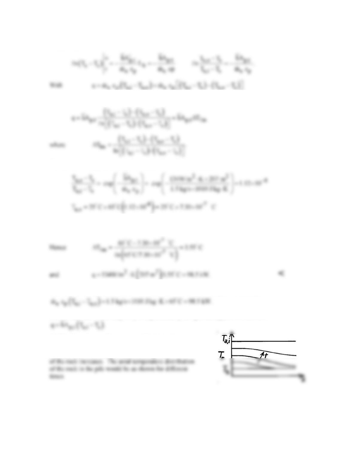
energy balance on a differential control volume about the rock. That is,
PROBLEM 7.85 (Cont.)
Integrating between inlet and outlet, it follows that
it follows that
The air outlet temperature may be obtained from the requirement
a,o s
T T 25 C.≈=
a
COMMENTS: (1) The above result may be checked from the requirement that q =
(2) The heat rate would be grossly overpredicted by using a rate equation of the form
(3) The foregoing results are reasonable during the
early stages of the heating process; however q would
decrease with increasing time as the temperature
PROBLEM 7.86
KNOWN: Dimensions of a pebble bed nuclear reactor. Dimensions of core and cladding of
pellets. Porosity of the reactor and helium properties, inlet temperature, and upstream velocity.
FIND: (a) Mean helium outlet temperature and amount of thermal energy generated per pellet for
an overall thermal energy transfer rate of q = 125 MW, (b) Maximum internal temperature of the
hottest pellet.
SCHEMATIC:
D = 3 m
L = 10 m
Helium
T
0
D
p
= 50 mm
q
T
s
T
s,1
δ= 5 mm
e= 0.4
e
j
H
=−−
+
1 0.35
DD
2.876Re 0.3023Re
D = 3 m
L = 10 m
Helium
T
0
D
p
= 50 mm
q
T
s
T
s,1
δ= 5 mm
e= 0.4
e
j
H
=−−
+
1 0.35
DD
2.876Re 0.3023Re
ASSUMPTIONS: (1) Negligible radiation heat transfer, (2) One-dimensional heat transfer, (3)
Uniform volumetric thermal generation inside the core, (4) Negligible contact resistance between
core and cladding.
ANALYSIS:
(a) From the simplified steady-flow thermal energy equation of Chapter 1 we may write
po i po i
q = mc (T – T ) = ρAVc (T – T )
PROBLEM 7.86 (Cont.)
The energy generated per pellet is
(b) The Reynolds number based on the pellet diameter is
From the problem statement we know
A sphere at the exit of the chamber will be adjacent to the highest helium temperature and will be,
in turn, the hottest. An energy balance about the single sphere yields
The temperature at the inner surface of the cladding may be found using Equation 3.40

PROBLEM 7.86 (Cont.)
The maximum temperature occurs at the center of the sphere at the exit plane. Beginning with
the heat equation for the pellet, find
Applying boundary conditions,
at r = 0,
1
r=0
dT dr = 0 C = 0→
COMMENTS: (1) The maximum temperature is below the temperature associated with
reduction in the thermal energy generation. (2) Helium is an excellent choice for the working
fluid due to its high thermal conductivity and extremely small nuclear cross section (Helium does
not absorb gamma radiation. Therefore the helium that exists the chamber can be fed directly to a
turbine as opposed to transferring thermal energy from the helium to a second working fluid.)
PROBLEM 7.87
KNOWN: Diameter and properties of phase–change material. Dimensions of cylindrical vessel and
porosity of packed bed. Inlet temperature and velocity of air.
FIND: (a) Outlet temperature of air and rate of melting, (b) Effect of inlet velocity and capsule
diameter on outlet temperature, (c) Location at which complete melting of PCM is first to occur and
subsequent variation of outlet temperature.
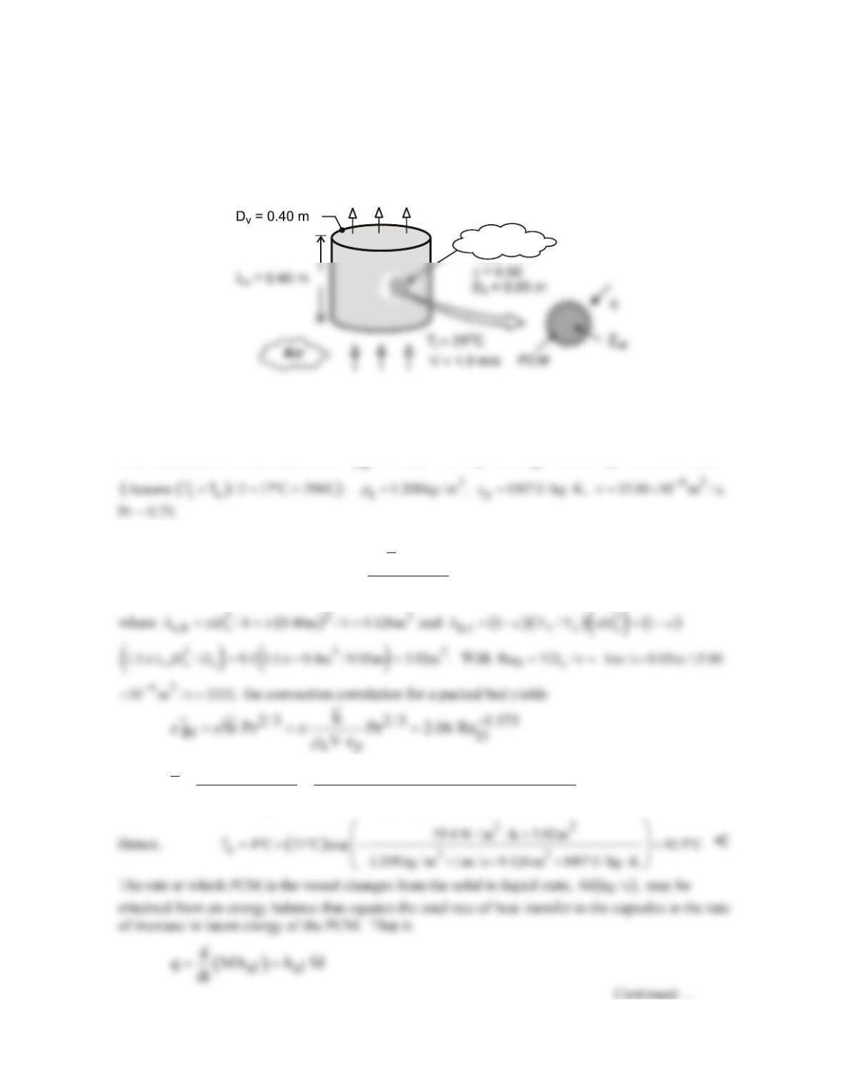
SCHEMATIC:
T
o
Packεd bεd
ASSUMPTIONS: (1) Negligible thickness (and thermal resistance) of capsule shell, (2) All capsules
are at Tmp, (3) Constant properties, (4) Negligible heat transfer from surroundings to vessel.
PROPERTIES: Prescribed, PCM:
3
mp
T 4 C, 1200 kg / m ,
r
=°=
sf
h 165 kJ / kg.=
Table A-4, Air
ANALYSIS: (a) For a packed bed the outlet temperature is given by
( )
p,t
o mp mp i a c,b p
hA
T T T T exp VA c
r
=−− −
( ) ( )
3
ap 2
2 / 3 0.575 2 / 3 0.575
D
2.06 V c 2.06 1.208 kg / m 1m / s 1007 J / kg K
h 59.4 W / m K
Pr Re 0.5 0.71 3333
r
e
× ×× ⋅
= = = ⋅
PROBLEM 7.87 (Cont.)
where M is the total mass of PCM and
Hence,
sf
M q / h 2220 W /165, 000 J / kg 0.0134 kg / s= = =
<
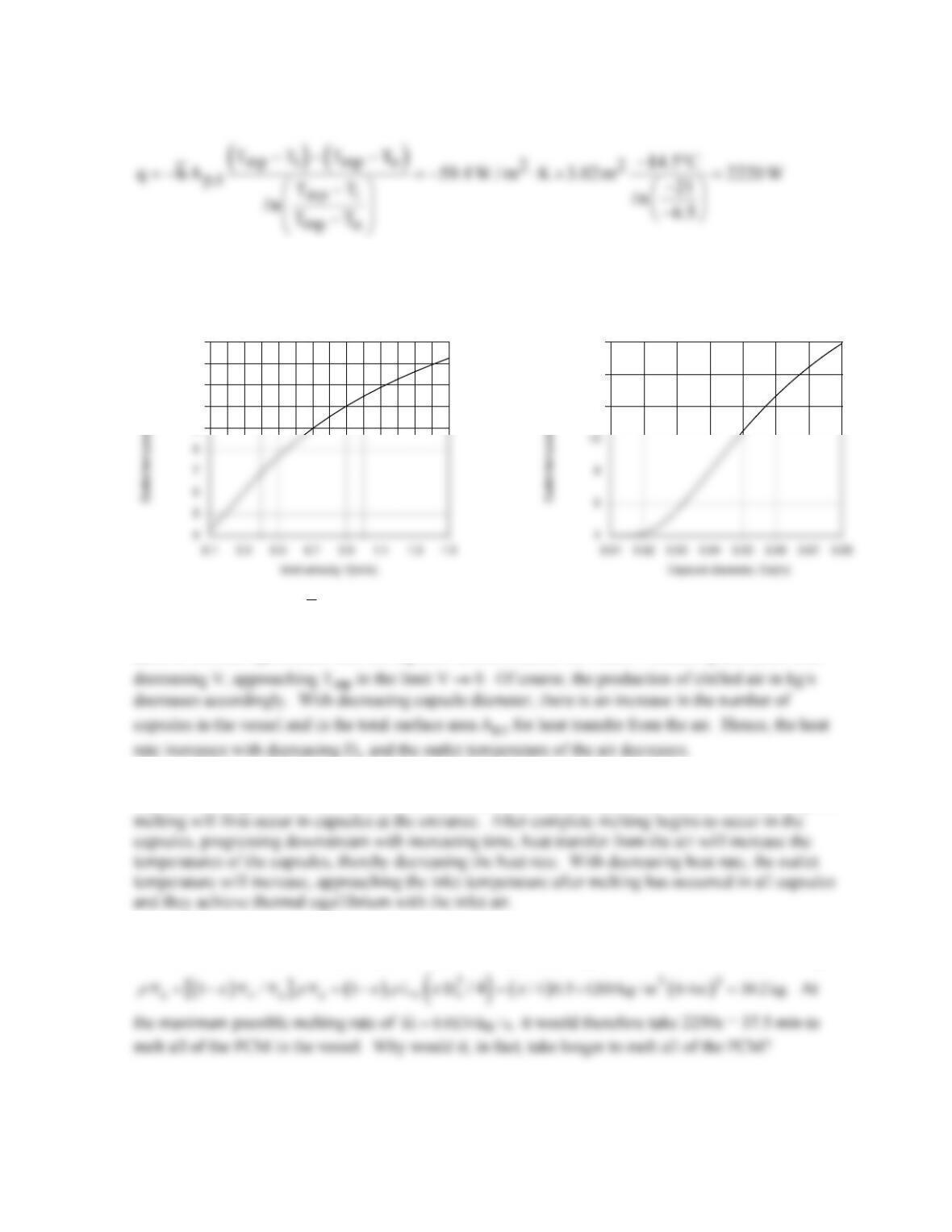
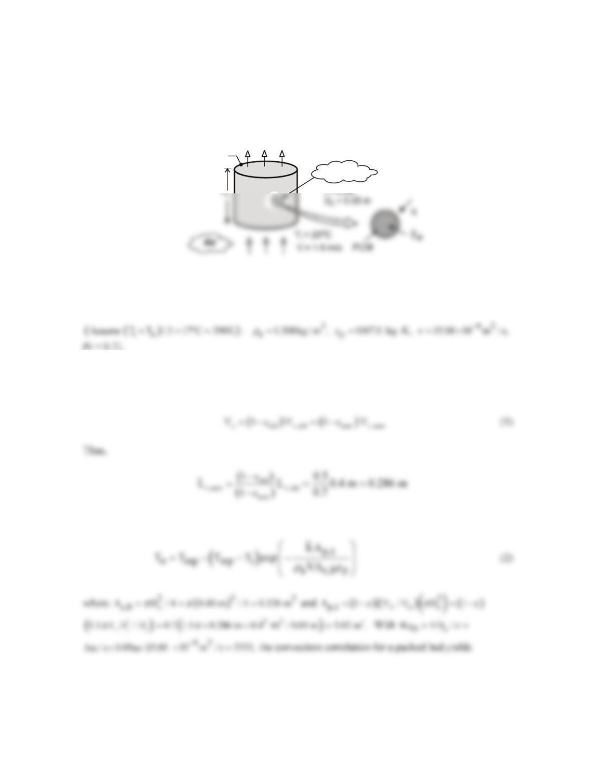
(b) The effect of the inlet velocity and capsule diameter are shown below.
Despite the reduction in
h
with decreasing V, the reduction in the mass flow rate of air through the
vessel and the corresponding increase in the residence time of air in the vessel allow it to more closely
achieve thermal equilibrium with the capsules before it leaves the vessel. Hence, To decreases with
(c) Because the temperature of the air decreases as it moves through the vessel, heat rates to the
capsules are largest and smallest at the entrance and exit, respectively, of the vessel. Hence, complete
COMMENTS: (1) The estimate of To used to evaluate the properties of air was good, and iteration
of the solution is not necessary. (2) The total mass of phase change material in the vessel is
c
MN=
9
10
11
12
13
12
14
16
PROBLEM 7.88
KNOWN: Diameter and properties of phase–change material. Dimensions of cylindrical vessel and
porosity of packed bed. Inlet temperature and velocity of air.
FIND: (a) Outlet temperature of air and rate of melting for e = 0.3 and length reduced to compensate,
(b) Outlet temperature of air and rate of melting for e = 0.3 and diameter reduced to compensate.
Which geometry is preferred.
SCHEMATIC:
ASSUMPTIONS: (1) Negligible thickness (and thermal resistance) of capsule shell, (2) All capsules
are at Tmp, (3) Constant properties, (4) Negligible heat transfer from surroundings to vessel.
PROPERTIES: Prescribed, PCM:
3
mp
T 4 C, 1200 kg / m ,
r
=°=
sf
h 165 kJ / kg.=
Table A-4, Air
ANALYSIS: (a) The new length of the vessel is determined from the fact that the same mass, or
volume, of capsules is now compressed to give a porosity of 0.3 instead of 0.5. We can relate the total
capsule volume,
c
∀
, to the vessel volume,
2
v vv
DL
π
∀
=
, as follows.
For a packed bed the outlet temperature is given by
Continued …
T
o
Packεd bεd
D
v
PROBLEM 7.88 (Cont.)
The rate at which PCM in the vessel changes from the solid to liquid state,
( )
M kg / s ,
may be
obtained from an energy balance that equates the total rate of heat transfer to the capsules to the rate of
increase in latent energy of the PCM. That is
where M is the total mass of PCM and
(b)The new vessel diameter is found from Eq. (1) to be
Since the mass flow rate of air is unchanged, the velocity must be increased to compensate for the
reduced diameter, thus
Repeating all of the calculations, we find

PROBLEM 7.88 (Cont.)
Then
q 2870 W=
and
This configuration results in a lower air outlet temperature and an increased PCM melting rate. <
COMMENTS: (1) The estimate of To used to evaluate the properties of air was reasonably good, and
iteration of the solution is not necessary. (2) Compared to Problem 7.87 which had e = 0.5, both of
these configurations yield a higher heat transfer coefficient and result in a lower outlet temperature and
PROBLEM 7.89
KNOWN: Diameter and properties of phase–change material. Dimensions of cylindrical vessel and
porosity of packed bed. Inlet temperature and velocity of air.
FIND: (a) Outlet temperature of air and rate of freezing, (b) Effect of inlet velocity and capsule
diameter on outlet temperature, (c) Location at which complete melting of PCM is first to occur and
subsequent variation of outlet temperature.
SCHEMATIC:
T
o
Packed bed
ASSUMPTIONS: (1) Negligible thickness (and thermal resistance) of capsule shell, (2) All capsules
are at Tmp, (3) Constant properties, (4) Negligible heat transfer from vessel to surroundings.
PROPERTIES: Prescribed, PCM: Tmp = 50°C,
3
sf
900 kg / m , h 200 kJ / kg.
r
= =
Table A-4, Air
ANALYSIS: (a) For a packed bed the outlet temperature is given by
D
Hence,
where M is the total mass of PCM and
Continued …
PROBLEM 7.89 (Cont.)
(b) The effect of V and Dc are shown below
Despite the reduction in
h
with decreasing V, the reduction in the mass flow rate of air in the vessel
and the corresponding increase in the residence time of air in the vessel allow it to more closely reach
thermal equilibrium with the capsules before it leaves the vessel. Hence, To increases with
decreasing V, approaching Tmp in the limit V → 0. Of course, the production of warm air in kg/s
COMMENTS: (1) The estimate of To used to evaluate the properties of air was good, and iteration
of the solution is not necessary. (2) The total mass of phase change material in the vessel is
46
48
50
50
PROBLEM 7.90
KNOWN: Dimensions, particle diameter, and porosity of bronze foam sheet. Temperature of upper
and lower surfaces of foam. Velocity and inlet temperature of air flowing through foam.
FIND: (a) Convection heat transfer rate to air assuming foam is at uniform temperature Ts. Whether
SCHEMATIC:
ASSUMPTIONS: (1) Steady–state conditions, (2) One-dimensional heat transfer, (3) Constant
properties, (4) Foam behaves as packed bed in part (a), (5) Foam behaves as extended surface in part
(b), (6) Negligible radiation transfer.
PROPERTIES: Table A-1, Commercial bronze (T
≈
325 K): kb = 52 W/m⋅K. Table A-4, Air (T
≈
325 K):
r
= 1.0782 kg/m3, cp = 1008 J/kg⋅K, k = 0.0282 W/m⋅K,
ν
= 18.41 × 10⁻⁶ m2/s, Pr = 0.704.
ANALYSIS: (a) The heat transfer coefficient can be found from Equation 7.81:
The surface area can be found as follows, where N = number of particles:
The outlet air temperature is given by Equation 7.83:
Ts = 80°C
D= 0.6 mm
e
= 0.25
W = 40 mm
Ts = 80°C