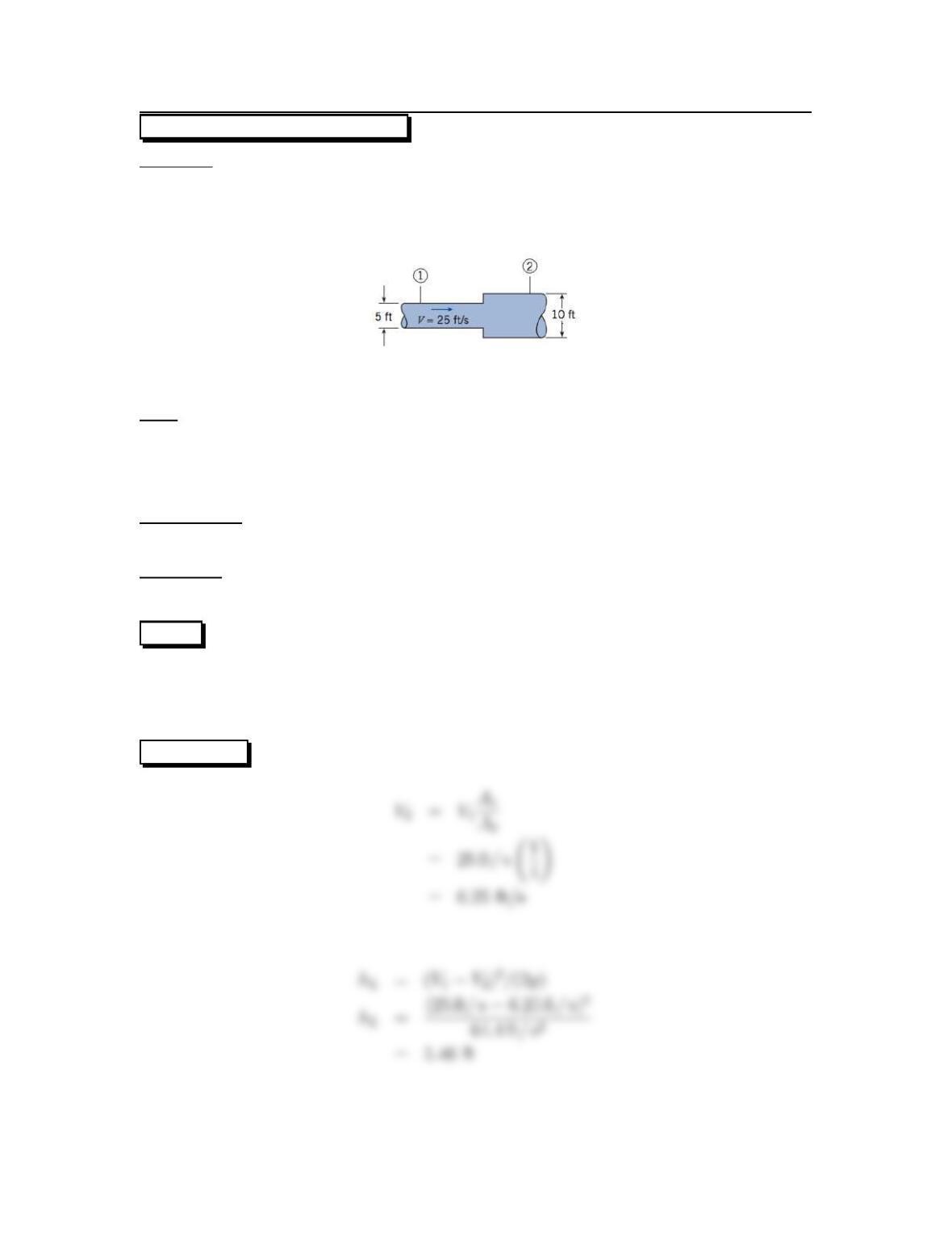
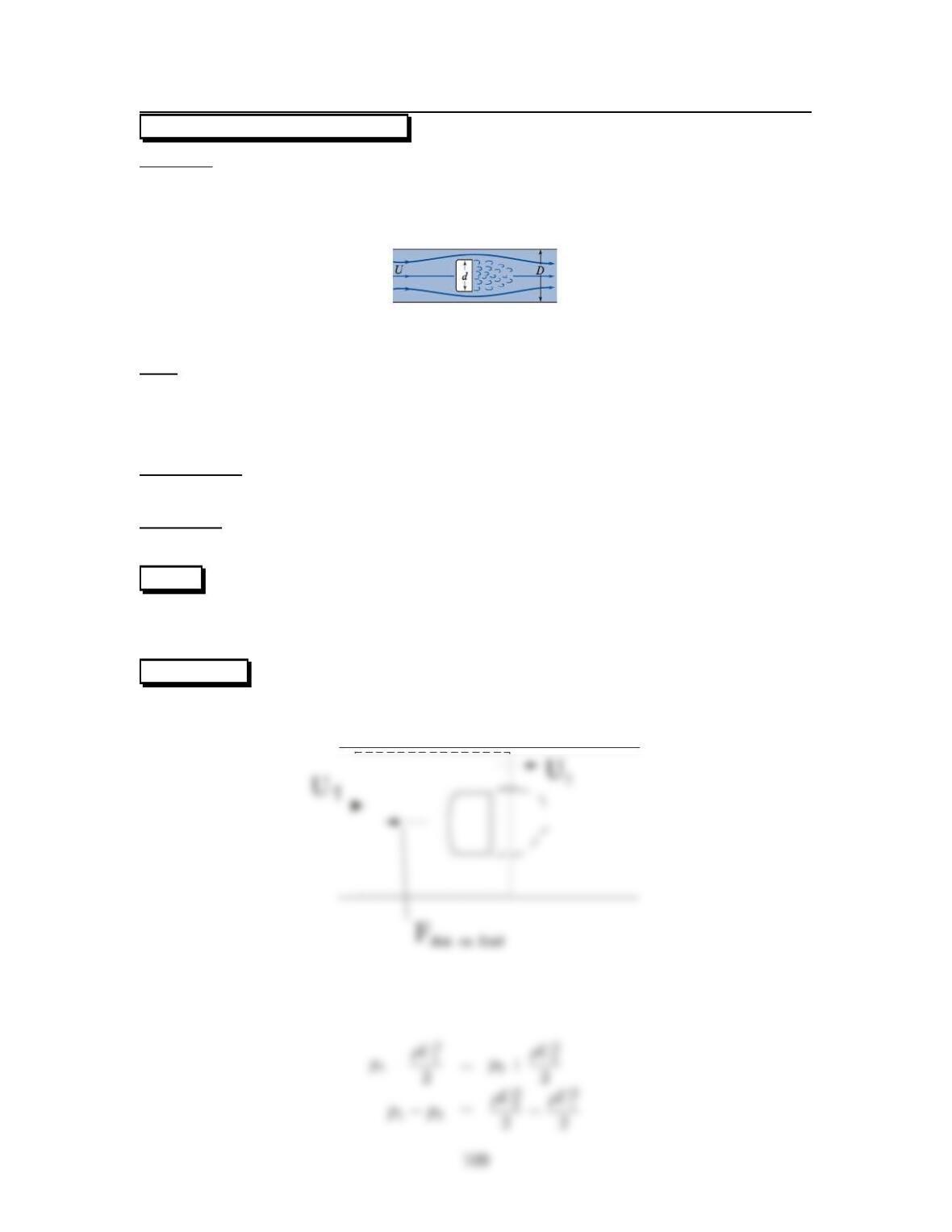
7.70: PROBLEM DEFINITION
Situation:
An abrupt expansion dissipates high energy flow.
D1=5ft,p1=5psig.
V=25ft/s,D2=10ft.
Find:
(a) Horsepower lost (hp).
(b) Pressure at section 2 (psig).
(c) Force needed to hold expansion (lbf).
Assumptions:
α=1.0.
Properties:
Water, γ=62.4lbf/ft3.
PLAN
Find the head loss by applying the sudden expansion head loss equation, first solving
for V2by applying the continuity principle. Then apply the power equation, the
energy equation, and finally the momentum principle.
SOLUTION Continuity equation
Sudden expansion head loss equation
101
a) Power equation
b) Energy equation
c) Momentum equation
102
7.71: PROBLEM DEFINITION
Situation:
Rough aluminum pipe discharges water.
L=50ft,D=6in.
W=(1.5lbf)L,Q=6cfs.
hL=10ft.
Find:
Longitudinal force transmitted through pipe wall (lbf).
Properties:
Water, γ=62.4lbf/ft3.
PLAN
Apply the energy equation, then the momentum principle.
SOLUTION
1
c.s.
103
Momentum principle
104
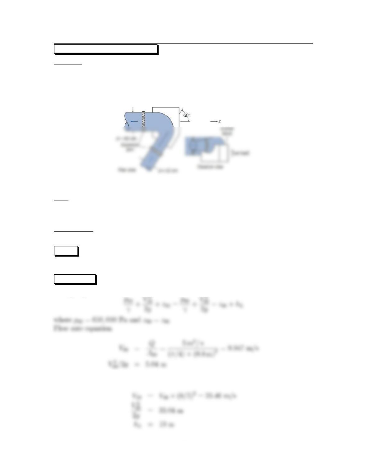
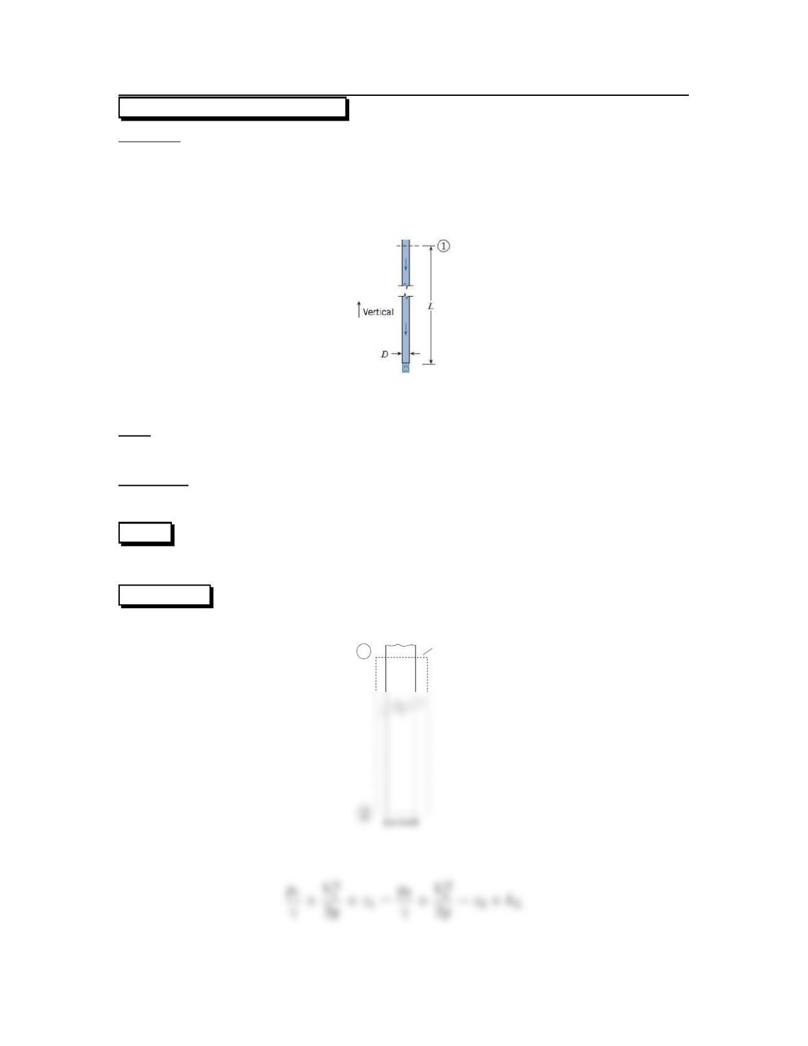
7.72: PROBLEM DEFINITION
Situation:
Water flows in a bend.
Q=5m
3/s,p=650kPa.
hL=10m,D=80cm.
d=50cm.
Find:
Pressure at outlet of bend (kPa).
Force on anchor block in the x-direction (kN).
Assumptions:
α=1.0.
PLAN
Apply the energy equation, then the momentum principle.
SOLUTION
Energy equation
Continuity equation
105
Then
Momentum principle
106
Problem 7.73
Situation:
Water flows in a bend
Q=7m3/s,P1=800 kPa
hL=13m,D=80cm.
d=50cm
Assume 1.0 at all locations.
Find:
Pressure at outlet of bend (kPa).
Force on anchor block in the x-direction (kN).
PLAN
Apply the energy equation, then the momentum principle.
SOLUTION
Flow rate equation
Continuity equation
107
Then
Momentum principle
108
7.74: PROBLEM DEFINITION
Situation:
Fluid in a pipe flows around an accelerated disk.
U=10m/s,D=5cm.
d=4cm.
Find:
Develop an expression for the force required to hold the disk in place in terms of
U, D, d, and ρ.
Force required under given conditions (N).
Assumptions:
α=1.0.
Properties:
ρ=1.2kg/m3.
PLAN
Apply the energy equation from section (1) to section (2), and apply the momentum
principle.
SOLUTION
Control volume
Energy equation
but
2´U2
(D2−d2)2−1¸(2)
Momentum principle for the C.V.
Eliminate p1−p2by Eq. (2), and U2by Eq. (1):
When U=10m/s, D=5cm, d=4cm and ρ=1.2kg/m3
110
Problem 7.75
Answer the following questions.
a. What are three important reasons that engineers use the HGL and EGL?
•Identifywhereheadlossisoccurring.
b. What factors influence the magnitude of the HGL? What factors influence the
magnitude of the EGL?
•Since the HGL =(p/γ)+z,thefactorsare:
c. How are the EGL and HGL related to the piezometer? To the stagnation tube?
•When liquid flows in a pipe, the HGL is coincident with the water level in a
d. How is the EGL related to the energy equation?
•The EGL involves three of the terms that appear in the energy equation.
e. How can you use an EGL or an HGL to determine the direction of flow?
•In a pipe of constant diameter, the flow goes from locations of high EGL &
111
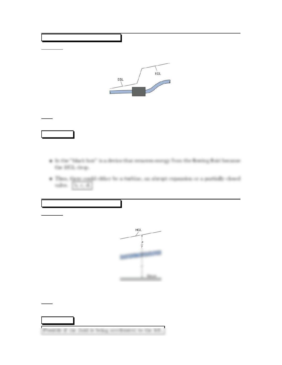
7.76: PROBLEM DEFINITION
Situation:
A piping system with a black box shows a large EGL change at the box.
Find:
What the black box could be.
SOLUTION
•Because the EGL slopes downward to the left, the flow is from right to left.
7.77: PROBLEM DEFINITION
Situation:
A constant diameter pipe is shown with an HGL.
Find:
Whether this system is possible, and if so under what conditions.
SOLUTION
112
7.78: PROBLEM DEFINITION
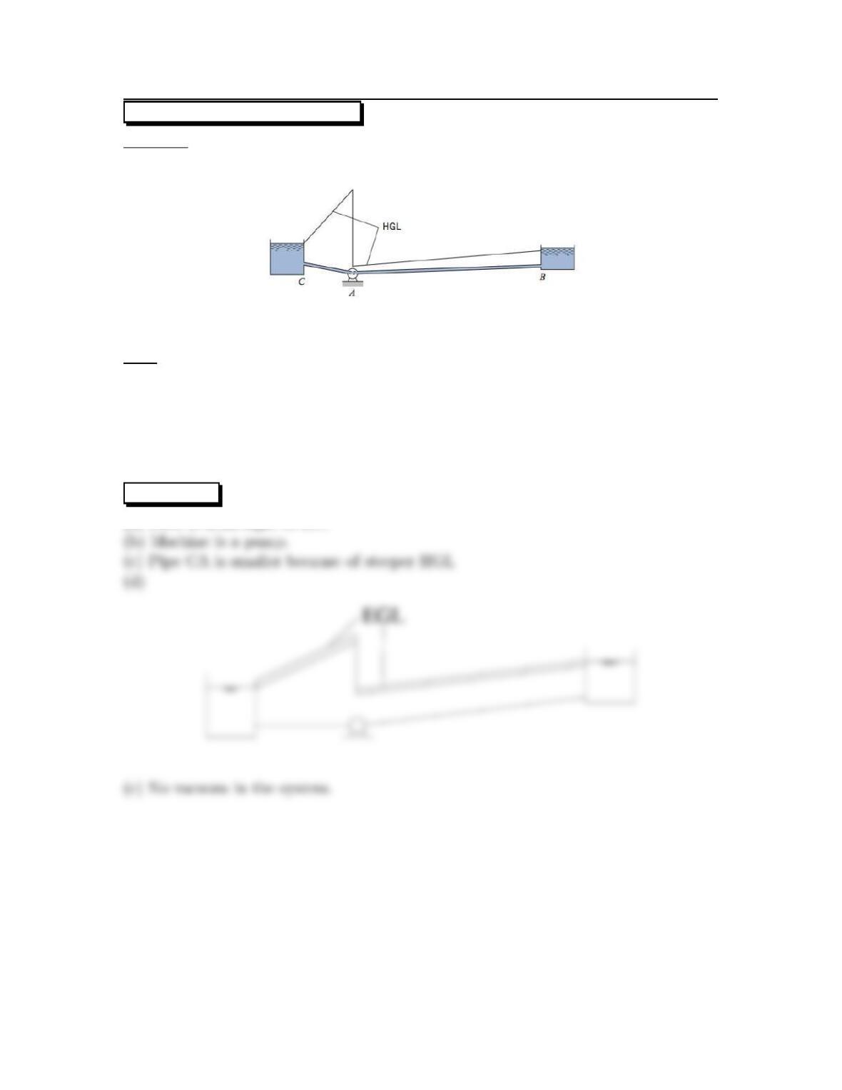
Situation:
Two tanks are connected by a pipe with a machine.
Find:
(a) Direction of flow.
(b) What kind of machine is at point A.
(c) Compare the diameter of pipe sections.
(d) Sketch the EGL.
(e) If there is a vacuum at anywhere, if so where it is.
SOLUTION
(a) Flow is from right to left.
113
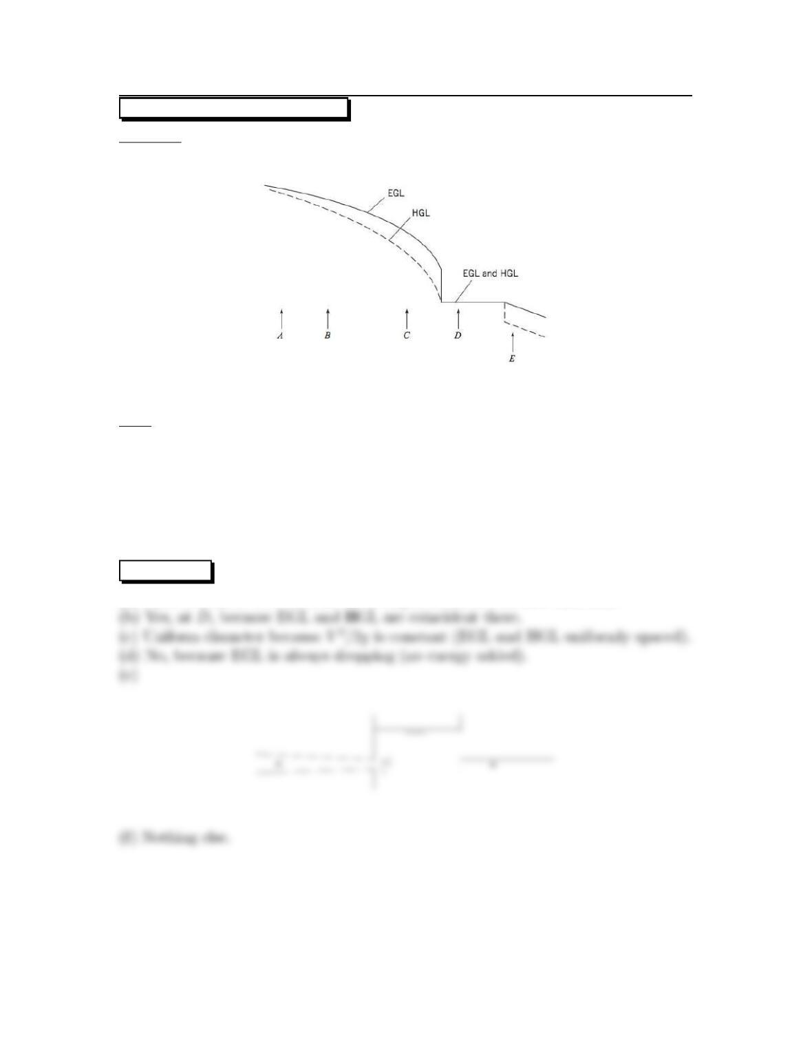
7.79: PROBLEM DEFINITION
Situation:
An HGL and EGL are shown for a flow system.
Find:
(a) Direction of flow.
(b) Whether there is a reservoir.
(c) Whether the diameter at E is uniform or variable.
(d) Whether there is a pump.
(e) Sketch a physical set up that could exist between Cand D.
(f) Whether there is anything else revealed by the sketch.
SOLUTION
(a) Flow is from Ato Ebecause EGL slopes downward in that direction.
114
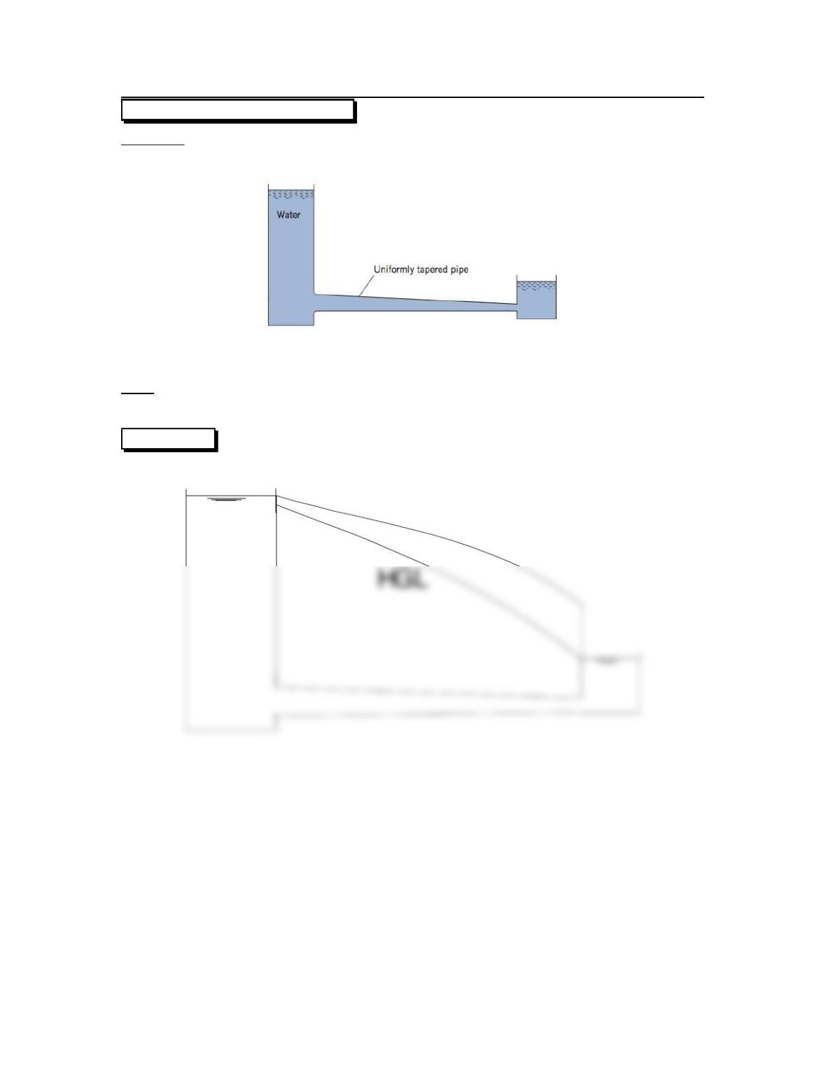
7.80: PROBLEM DEFINITION
Situation:
Two tanks are connected by a uniformly tapered pipe.
Find:
Draw the HGL and EGL.
SOLUTION
EG L
115
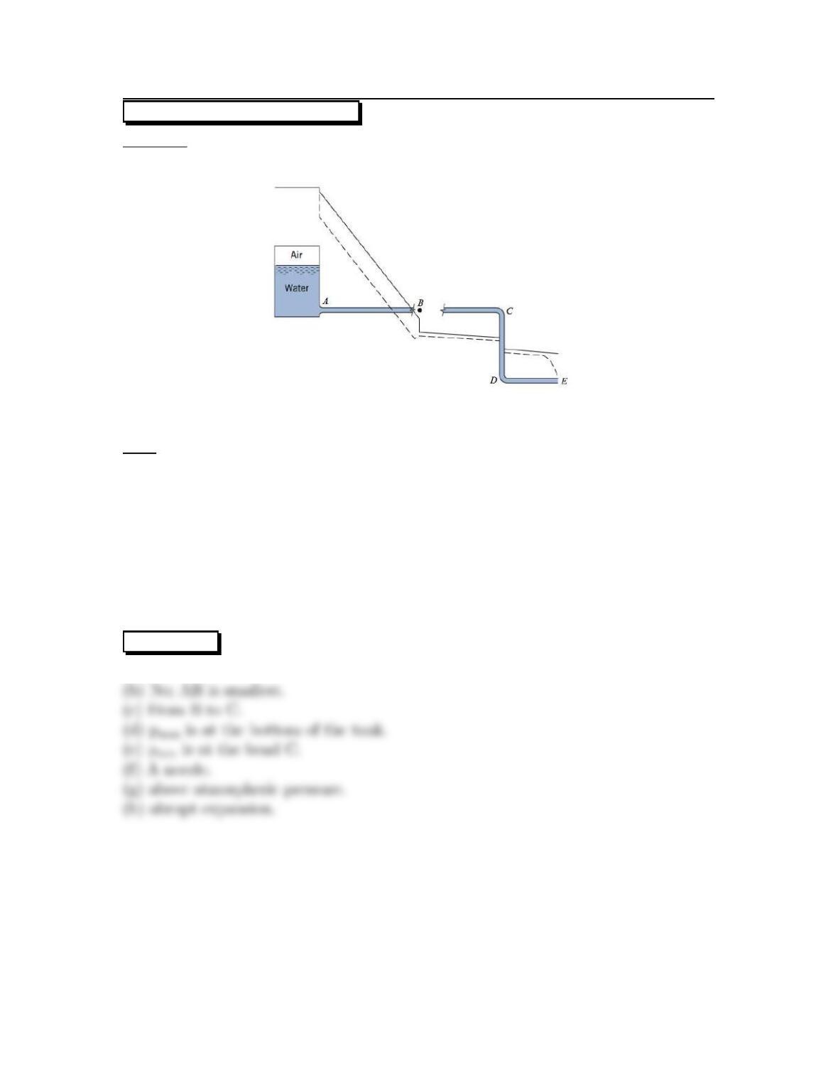
7.81: PROBLEM DEFINITION
Situation:
A system with an HGL and EGL is described in the problem statement.
Find:
(a) Which line is HGL and which is EGL.
(b) If pipes are the same size and which is smallest.
(c) If and where pipe pressure falls below zero.
(d) Point of max pressure.
(e) Point of minimum pressure.
(f)WhatisatpointE.
(g) Air pressure in the tank above or below atmospheric.
(h)WhatisatpointB.
SOLUTION
(a) Solid line is EGL, dashed line is HGL.
116
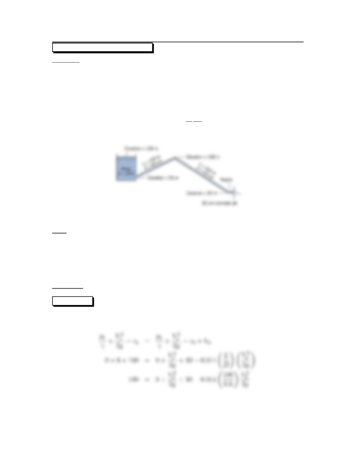
7.82: PROBLEM DEFINITION
Situation:
Water flows from a tank through a pipe system before discharging through a nozzle.
z1=100m,z2=30m.
L1=100m,L2= 400 m.
D1=D2=60cm,Djet =30cm.
Head loss in the pipe is given by
hL=0.014 L
D
V2
p
2g
Find:
(a) Discharge.
(b) Draw HGL and EGL.
(c) location of maximum pressure.
(d) location of minimum pressure.
(e) values for maximum and minimum pressure.
Properties:Water(15 ◦C), Table A.5, γ=9800N/m3.
SOLUTION
Energy equation (locate 1 on the reservoir water surface; locate 2 at outlet of the
nozzle).
Continuity equation
117
Then
Flow rate equation
Minimum pressure. Apply the Energy equation (point 1 on reservoir surface; point 2
in pipe at location of minimum pressure)
118
Maximum pressure. Apply the Energy equation (point 1 on reservoir surface; point
2 in pipe at location of maximum pressure)
119