Problem 7-1
module Prob_7_1 (output [3: 0] count, input enable, clock, reset);
Prob_7_1_Control_Unit M0 (enable_DP, enable, clock, reset);
Prob_7_1_Datapth_Unit M1 (count, enable_DP, clock, reset);
endmodule
always @(posedge clock, posedge reset)
if (reset) count <= 0;
else count <= next_count(count);
function [3: 0] next_count;
input [3: 0] count;
Prob_7_1 M0 (count, enable, clock, reset);
initial #50 $finish;
initial begin clock = 0; forever #5 clock = ~clock; end
Problem 7-2
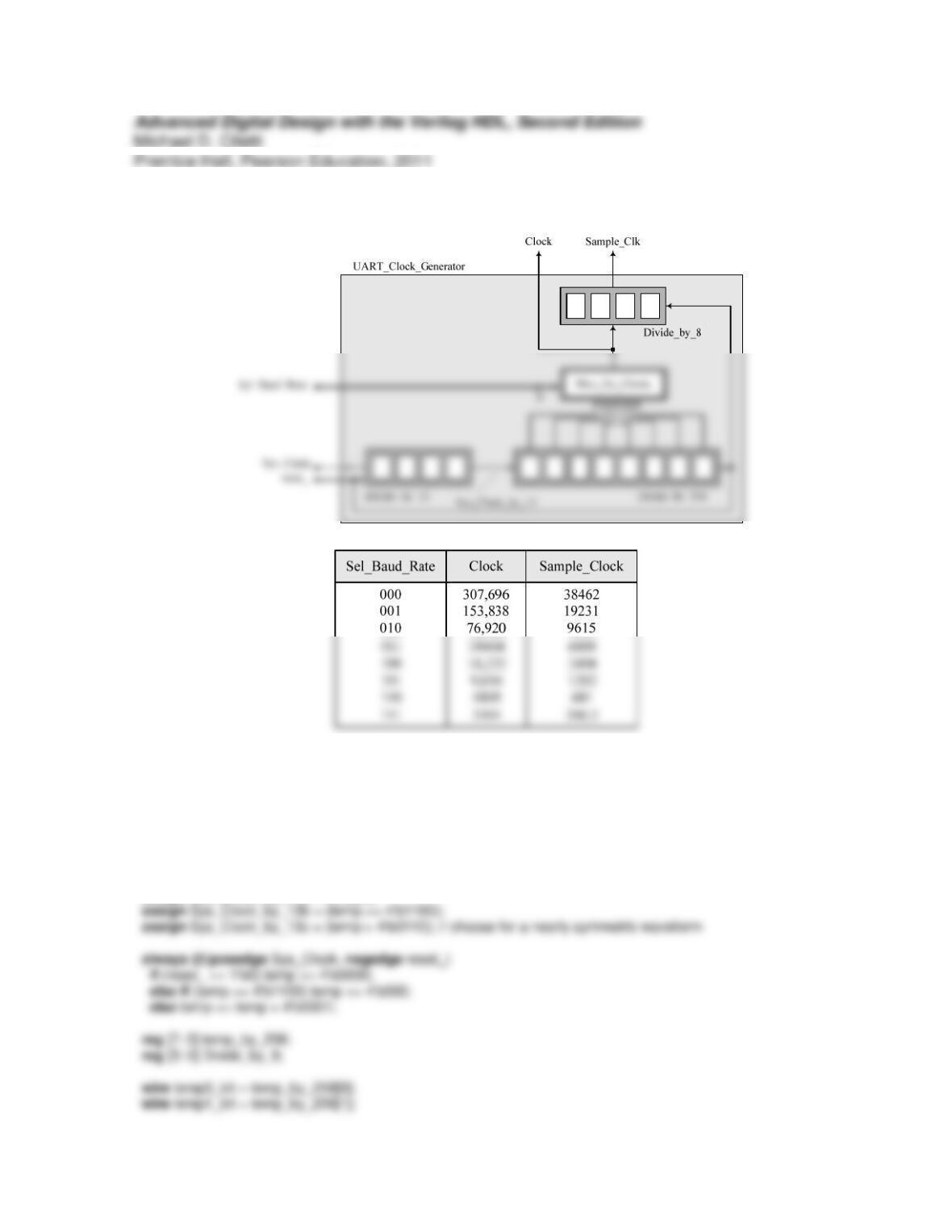
The three waveforms for the divided clock (by 13) have relatively minor differences in their
synthesized circuit (details left to student). The symmetric clock would have more balance in
the time intervals available for meeting setup and hold conditions.
module Problem_7_2_Divide_by_13 (output Clock, Sample_Clk, Sys_Clock_by_13a, Sys_Clock_by_13b,
Sys_Clock_by_13c, input [2: 0] Sel_Baud_Rate, input Sys_Clock, reset_);
reg [3: 0] temp;
assign Sys_Clock_by_13a = temp[3];
wire temp2_bit = temp_by_256[2];
wire temp3_bit = temp_by_256[3];
assign Clock = ((temp0_bit) && (Sel_Baud_Rate == 3’b000))
|| ((temp1_bit) && (Sel_Baud_Rate == 3’b001))
|| ((temp2_bit) && (Sel_Baud_Rate == 3’b010))
always @(posedge Sys_Clock_by_13a, negedge reset_) // Explore other options
if (reset_ == 1’b0) temp_by_256 <= 8’b0;
else temp_by_256 <= temp_by_256 + 1;
always @(posedge Clock, negedge reset_)
if (reset_ == 1’b0) Divide_by_8 <= 0;
else if (Divide_by_8 == 4’b0111) Divide_by_8 <= 4’b0000;
else Divide_by_8 <= Divide_by_8 + 1;
assign Sample_Clk = Divide_by_8[2];
endmodule
initial #5000000 $finish;
// Must create an 8 MHz system clock (period = 125 ns)
initial begin Sys_Clock = 0; forever #62.5 Sys_Clock = Sys_Clock + 1; end
initial fork
reset_ = 1;
#10 reset_ = 0;
#12 reset_ = 1;
join
endmodule
Problem 7-3
The unused counts of the codes of the Johnson counter can be mapped into any of the used
counts, but for this solution the codes defined by 4’b0—0 are mapped to 4’b0001. The
testbench uses the force … release procedural continuous assignment to force count to an
abnormal value, followed by a release. Note that count recovers at the first active edge of
module Prob_7_3 (output reg [3: 0] count, input clock, reset);
always @ (posedge clock, posedge reset)
if (reset === 1’b1) count <= 4’b0;
else case (count)
4’b0000: count <= 4’b0001;
module test_Prob_7_3 ();
wire [3: 0] count;
reg clock, reset;
Prob_7_3 M0(count, clock, reset);
initial #300 $finish;

#80 force M0.count = 4’b0110;
#118 release M0.count;
Problem 7-4
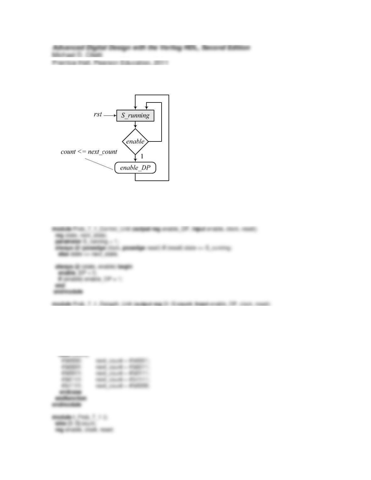
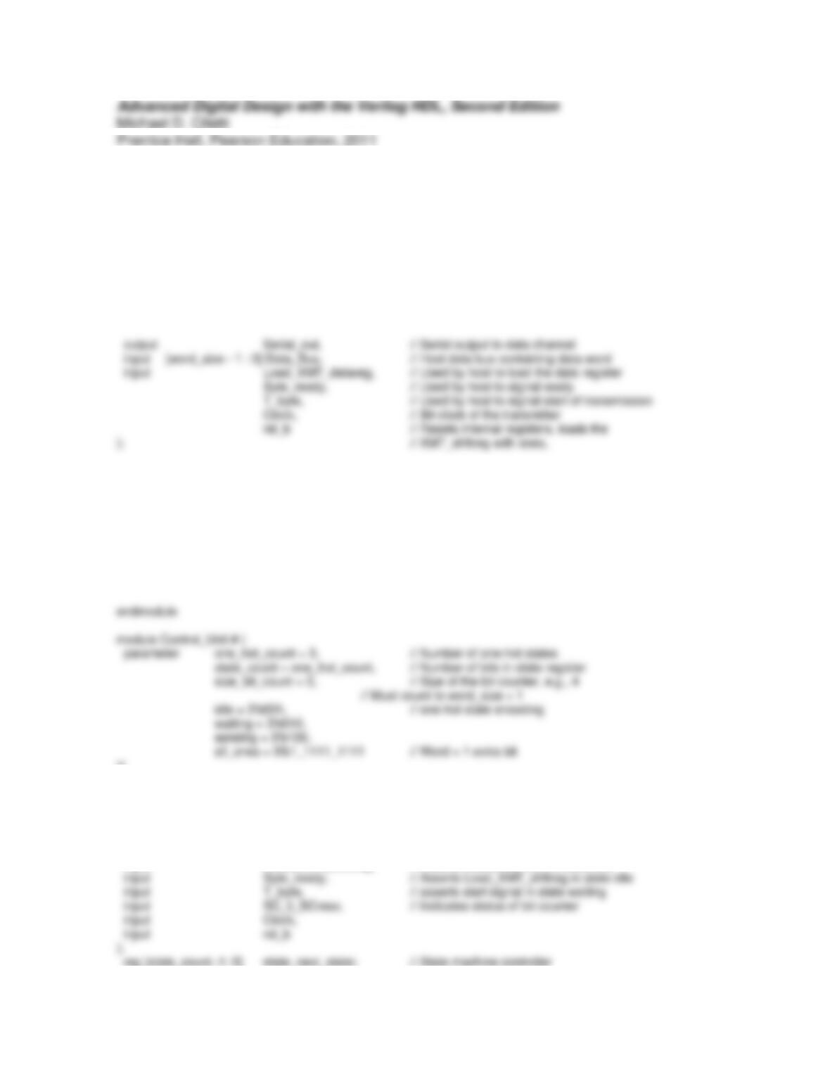
Modify the counter by replacing the controller with one having the ASM chart show below.
Problem 7-5
Because the signals controlling the datapath operations are asserted under mutually exclusive
conditions (see the ASMD chart), a priority decoder is not needed.
A model using a priority decoder is given below.
module UART_XMTR_Priority_Decoder # (parameter word_size = 8)( // Size of data, e.g., 8 bits
Control_Unit M0 (
Load_XMT_DR, Load_XMT_shftreg, start, shift, clear, Load_XMT_datareg, Byte_ready, T_byte,
BC_lt_BCmax, Clock, rst_b
);
Datapath_Unit_Priority_Decoder M1 (
Serial_out, BC_lt_BCmax, Data_Bus, Load_XMT_DR, Load_XMT_shftreg, start, shift,
clear, Clock, rst_b
);
)(
output reg Load_XMT_DR, // Loads Data_Bus into XMT_datareg
output reg Load_XMT_shftreg, // Loads XMT_datareg into XMT_shftreg
output reg start, // Launches shifting of bits in XMT_shftreg
output reg shift, // Shifts bits in XMT_shftreg
output reg clear, // Clears bit_count after last bit is sent
input Load_XMT_datareg, // Asserts Load_XMT_DR in state idle
shift = 0;
clear = 0;
next_state = idle;
case (state)
idle: if (Load_XMT_datareg == 1’b1) begin
Load_XMT_DR = 1;
next_state = idle;
end
else if (Byte_ready == 1’b1) begin
Load_XMT_shftreg = 1;
next_state = waiting;
end
end
default: next_state = idle;
endcase
end
always @ (posedge Clock, negedge rst_b) begin: State_Transitions
if first_b == 1’b0) state <= idle; else state <= next_state; end
endmodule
module Datapath_Unit_Priority_Decoder # (
parameter word_size = 8,
size_bit_count = 3,
if first_b == 0) begin
XMT_shftreg <= all_ones;
bit_count <= 0;
end
else begin :Register_Transfers
if (Load_XMT_DR == 1’b1) XMT_datareg <= Data_Bus; // Get the data bus
Problem 7-8
(a)
module Prob_7_8_Binary_Counter_Arch #(parameter word_size = 8)(
output [word_size -1: 0]count, input enable, clk, rst
module Datapath_Unit_Arch #(parameter word_size = 8)(
output [word_size -1: 0] count,
input enable_DP, clk, rst
);
wire [word_size -1: 0] sum, mux_out;
Count_Register M0 (
.data_out(count),
.data_in(mux_out),
.clk(clk),
.rstfirst)
assign mux_out = enable_DP ? mux_in1: mux_in0;
endmodule
module Count_Register #(parameter word_size = 8)(
output reg [word_size -1: 0] data_out, input [word_size -1: 0] data_in, input clk, rst);
module Incrementer #(parameter word_size = 8)(
output [word_size -1: 0] sum,
input [word_size -1: 0] data
rst = 1;
#20 rst = 1;
#30 rst = 0;
#100 rst = 1;
#120 rst = 0;
(b) The implicit state machine model of the counter is given below.
module Prob_7_8_Binary_Counter_Behav_imp #(parameter word_size = 4)(
output reg [word_size -1: 0]count, input enable, clk, rst
);
always @ (posedge clk, posedge rst)
Prob_7_8_Binary_Counter_Behav_imp M0 (count, enable, clk, rst);
initial #5000 $finish;
initial begin clk = 0; forever #5 clk = ~clk; end
initial fork
rst = 1;
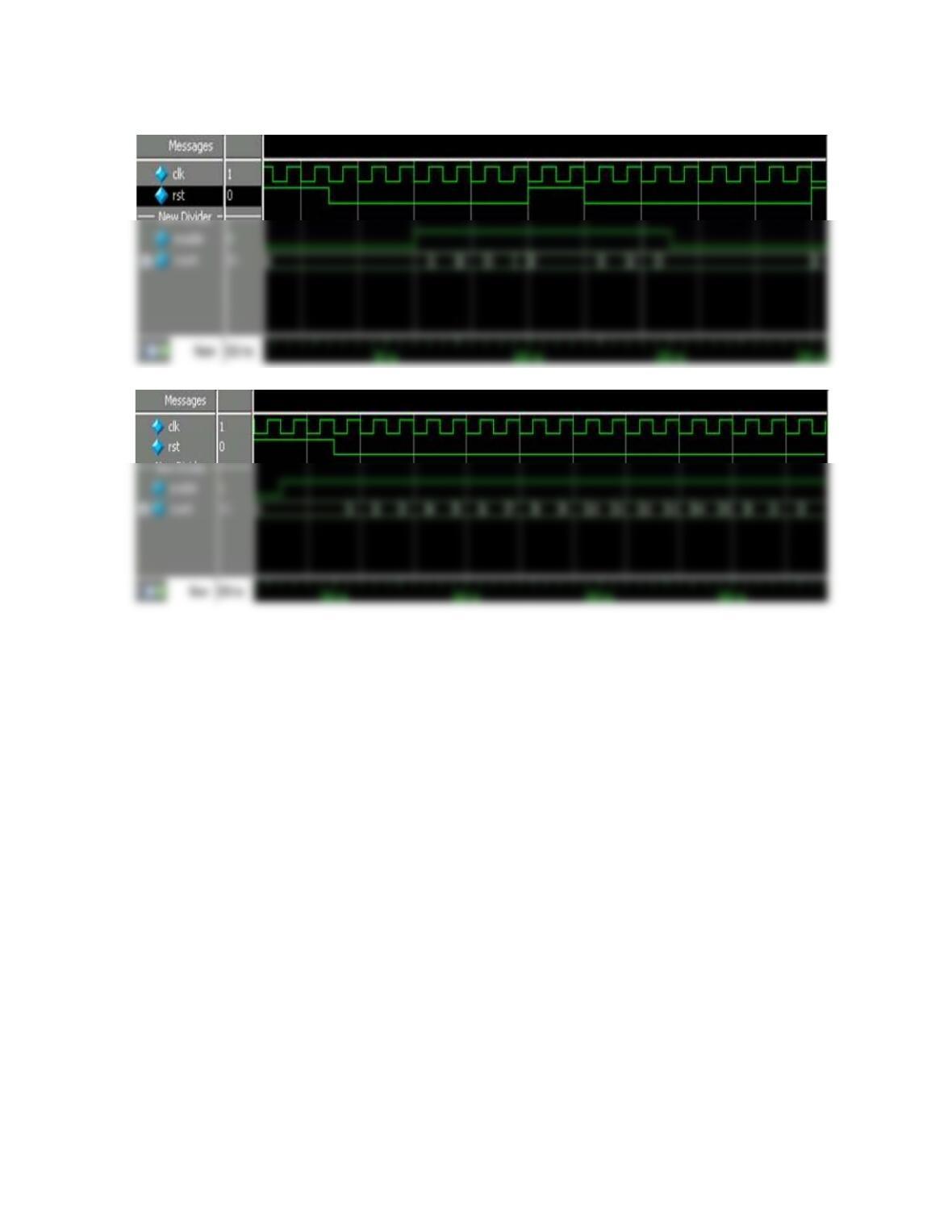
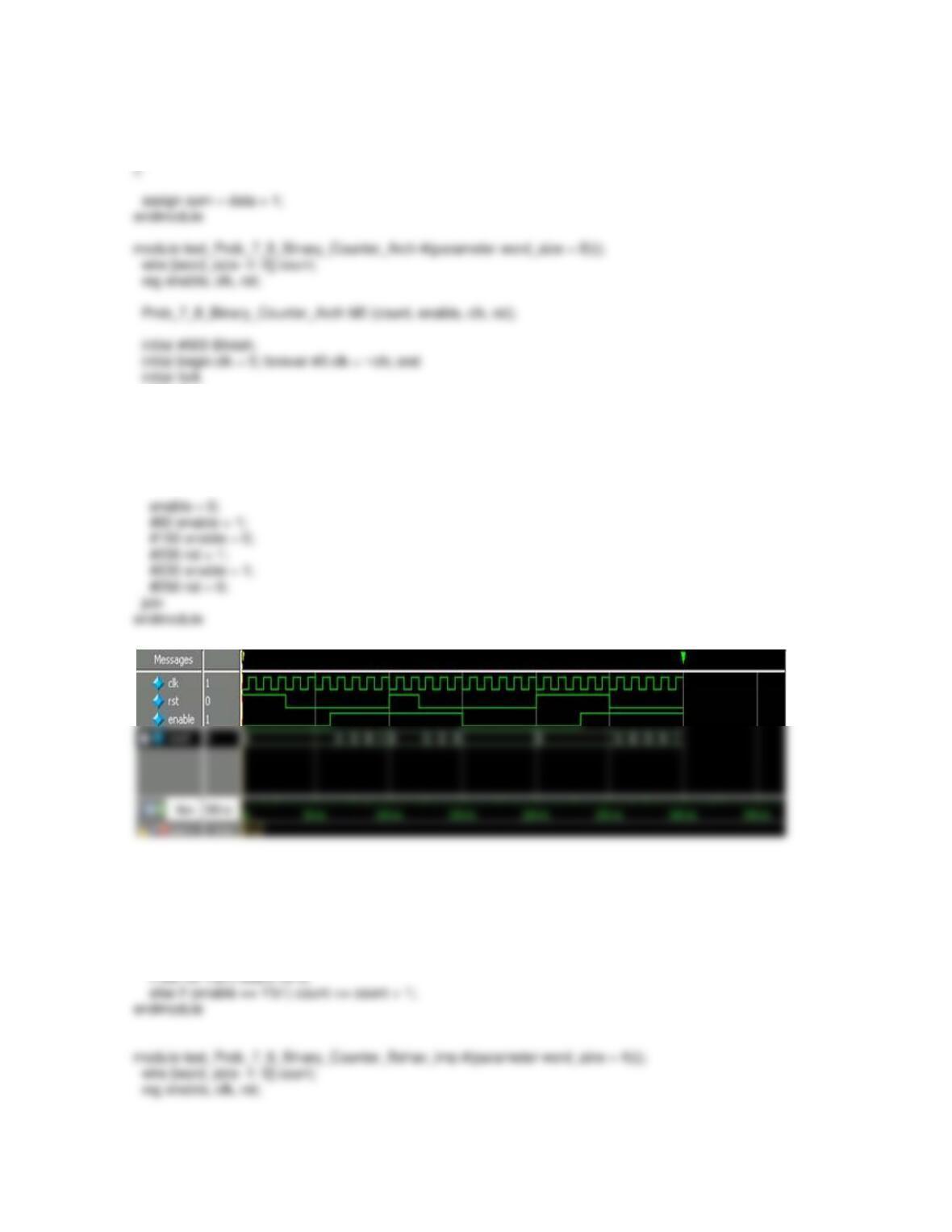
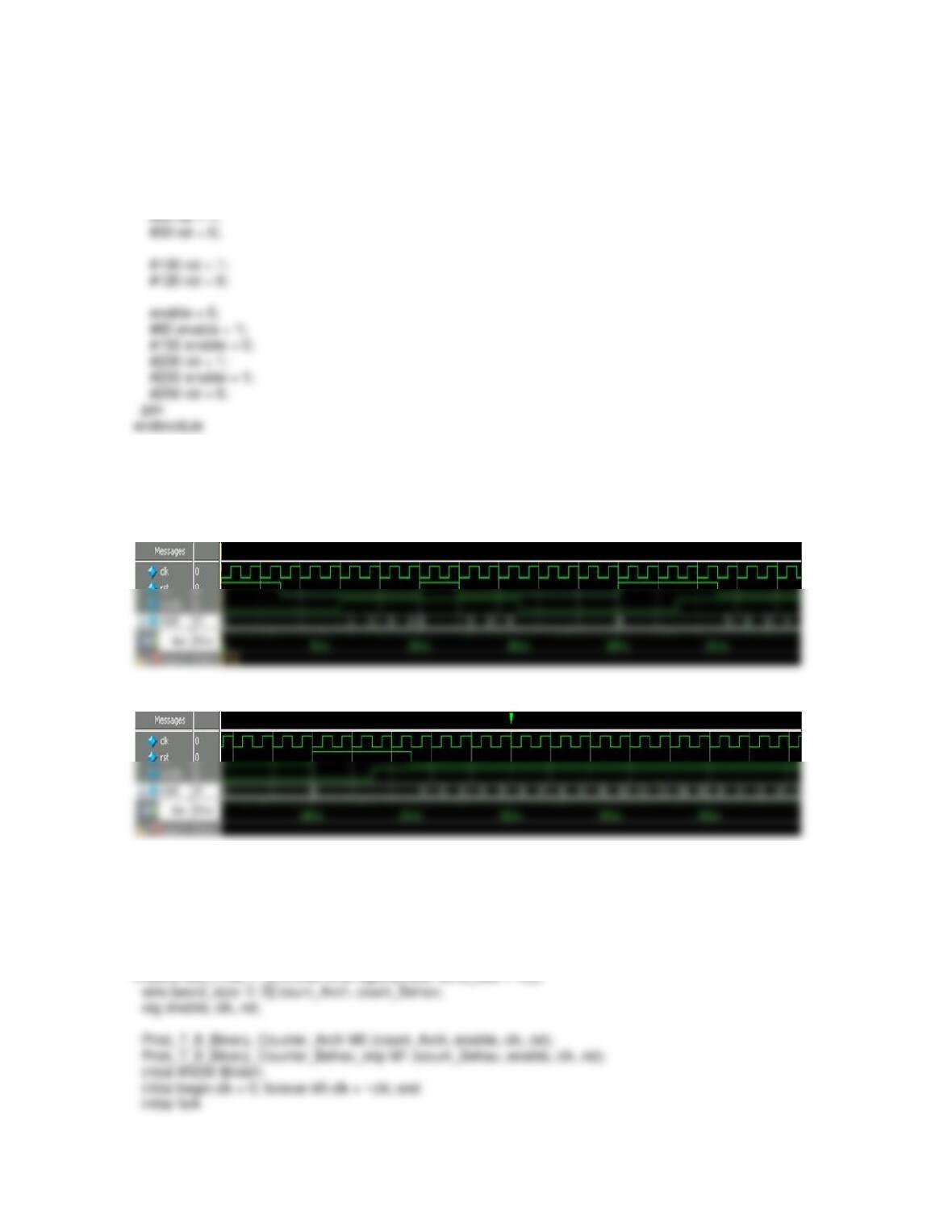
Simulation results for Prob_7_8_Binary_Counter_Behav_imp are shown below. The reader is
encouraged to confirm that they match those that would be produced by a simulation of
Prob_7_8_Binary_Counter_Arch with word_size = 4.
(c) Left to the student.
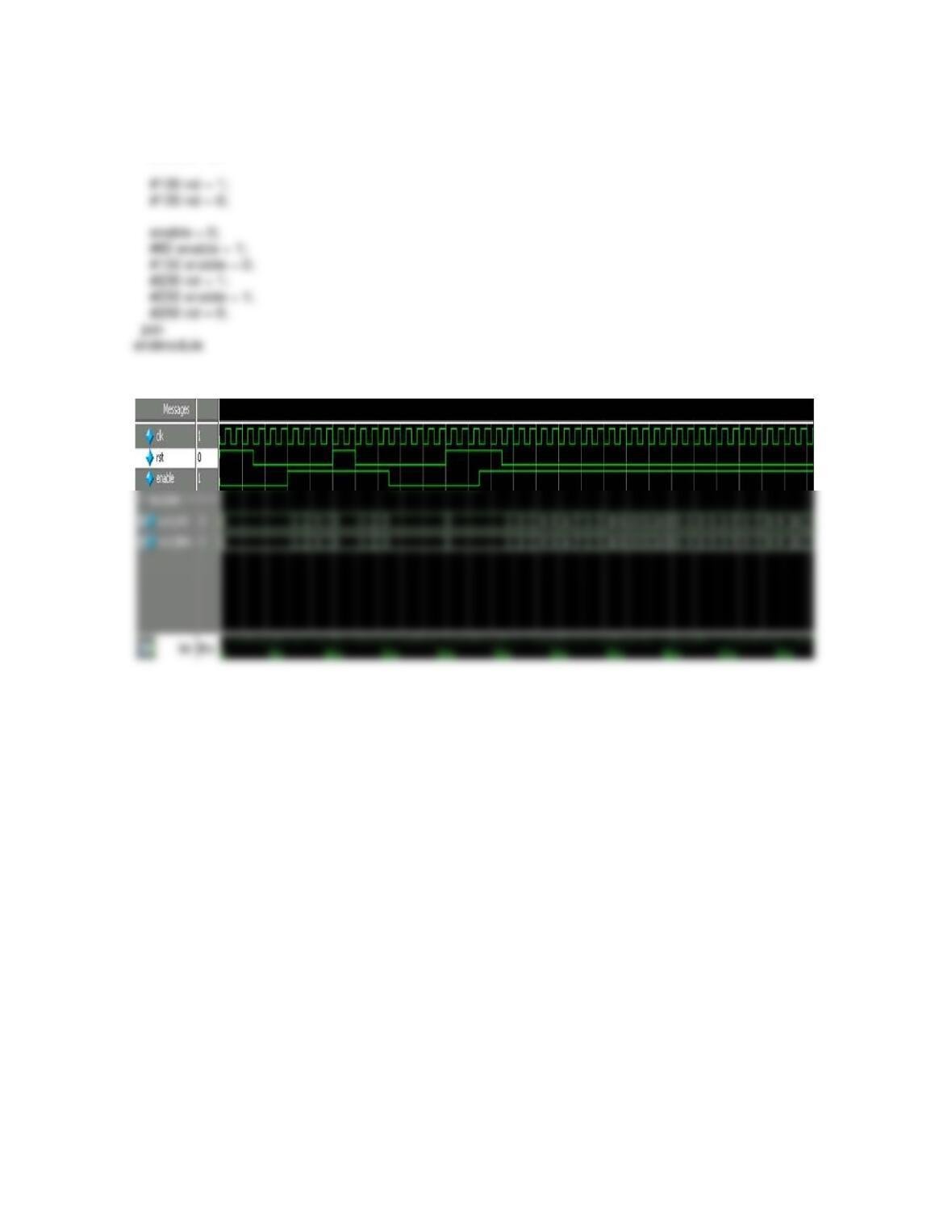
(d) The common testbench for comparing Binary_Counter_Arch and
Binary_Counter_Behav_imp is given below with a sample of simulation results.
rst = 1;
#20 rst = 1;
#30 rst = 0;
Problem 7-9
module prob_7_9_Binary_Counter_STG # (parameter word_size = 4)(
output reg [word_size -1: 0] count, input enable, clk, rst
);
always @ (posedge clk, posedge rst)
if first == 1’b1) count <= 4’b0;
else if (enable == 1’b1)
case (count)
4’b0000: count <= 4’b0001;
4’b0001: count <= 4’b0010;
4’b0010: count <= 4’b0011;
module test_prob_7_9_Binary_Counter_STG #(parameter word_size = 4)();
wire [word_size -1: 0] count;
reg enable, clk, rst;
prob_7_9_Binary_Counter_STG M0 (count, enable, clk, rst);
initial #5000 $finish;
initial begin clk = 0; forever #5 clk = ~clk; end
initial fork
rst = 1;
#20 rst = 1;
#30 rst = 0;
#100 rst = 1;
#120 rst = 0;