Fluid Flow in Soils and Rock Chapter 7
CHAPTER 7
FLUID FLOW IN SOILS AND ROCK
7-1. A clean sand having a permeability of 4.5 x 10⁻³ cm/s and a void ratio of 0.45 is placed in a
horizontal permeability apparatus, as shown in Fig. 7.2. Compute the discharge velocity and the
seepage velocity as the head
Δ
h goes from 0 to 80 cm. The cross-sectional area of the horizontal
pipe is 95 cm2, and the soil sample is 0.65 m long.
SOLUTION:
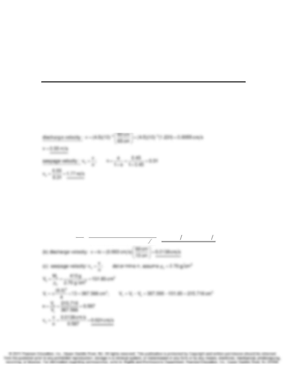
Eq. 7.5 : v ki
=
7-2. A sample of medium quartz sand is tested in a constant head permeameter. The sample’s
diameter is 60 mm and its length is 130 mm. Under an applied head of 60 cm, 119 cm3 flows
through the sample in 5 min. The Ms of the sample is 410 g. Calculate (a) the Darcy coefficient of
permeability, (b) the discharge velocity, and (c) the seepage velocity. (After A. Casagrande.)
SOLUTION:
3
3
2smin
QL (119 cm )(13.0 cm)(4)
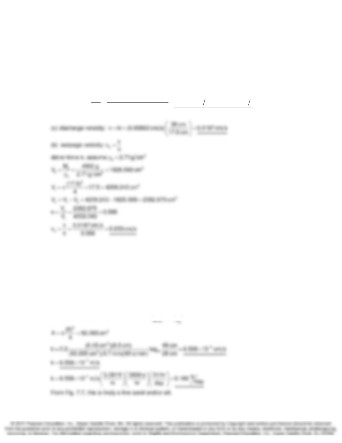
(a) Eq. 7.9 : k 0.003 cm s 3 10 cm s
hAt (60 cm) (6.0 cm) (5 min)(60 )
−
== = =×
π
Fluid Flow in Soils and Rock Chapter 7
7-3. A permeability test was run on a compacted sample of dirty sandy gravel. The sample was
175 mm long and the diameter of the mold 175 mm. In 90 s the discharge under a constant head
of 38 cm was 405 cm3. The sample had a dry mass of 4950 g and its
ρ
s was 2710 kg/m3.
Calculate (a) the coefficient of permeability, (b) the seepage velocity, and (c) the discharge
velocity during the test.
SOLUTION:
3
3
2
QL (405 cm )(17.5 cm)(4)
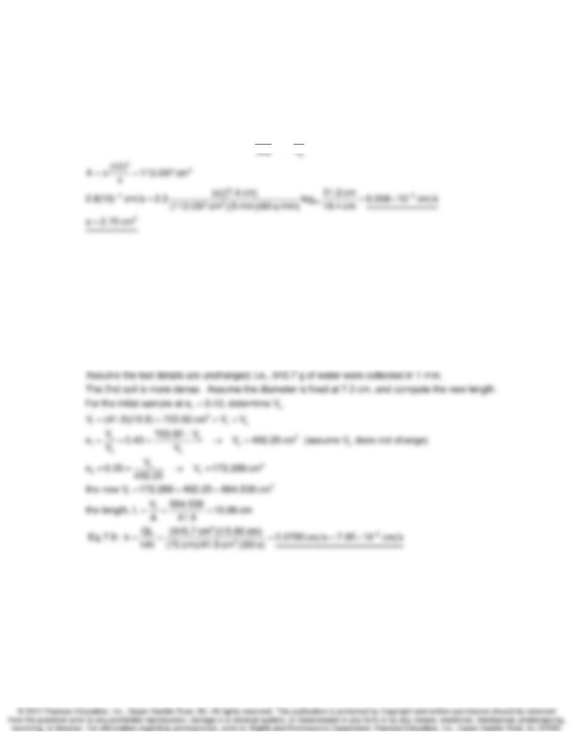
(a) Eq. 7.9 : k 0.00862 cm s 8.62 10 cm s
hAt (38cm) (17.5cm) (90s)
−
== = =×
π
7-.4. During a falling-head permeability test, the head fell from 49 to 28 cm in 4.7 min. The
specimen was 8 cm in diameter and had a length of 85 mm. The area of the standpipe was 0.45
cm2. Compute the coefficient of permeability of the soil in cm/s, m/s. and ft/d. What was the
probable classification of the soil tested? (After A. Casagrande.)
SOLUTION:
1
10
h
aL
Falling head test, use Eq. 7.10b: k 2.3 log
=Δ
Fluid Flow in Soils and Rock Chapter 7
7-5. A falling-head permeability test is performed on a soil whose permeability is estimated to be
2.8 x 10⁻⁶ m/s. What diameter standpipe for head to drop from 31.2 cm to 19.4 cm in about 5
min? The cross section is 12 cm2 and its length is 7.4 cm. (Taylor, 1948.)
SOLUTION:
1
10
h
aL
Falling head test, use Eq. 7.10b: k 2.3 log
=Δ
7-8. In Example 7.1, the void ratio is specified as 0.43. If the void ratio of the same soil were
0.35, evaluate its coefficient of permeability. First estimate in which direction k would go, higher or
lower; then proceed.
SOLUTION:
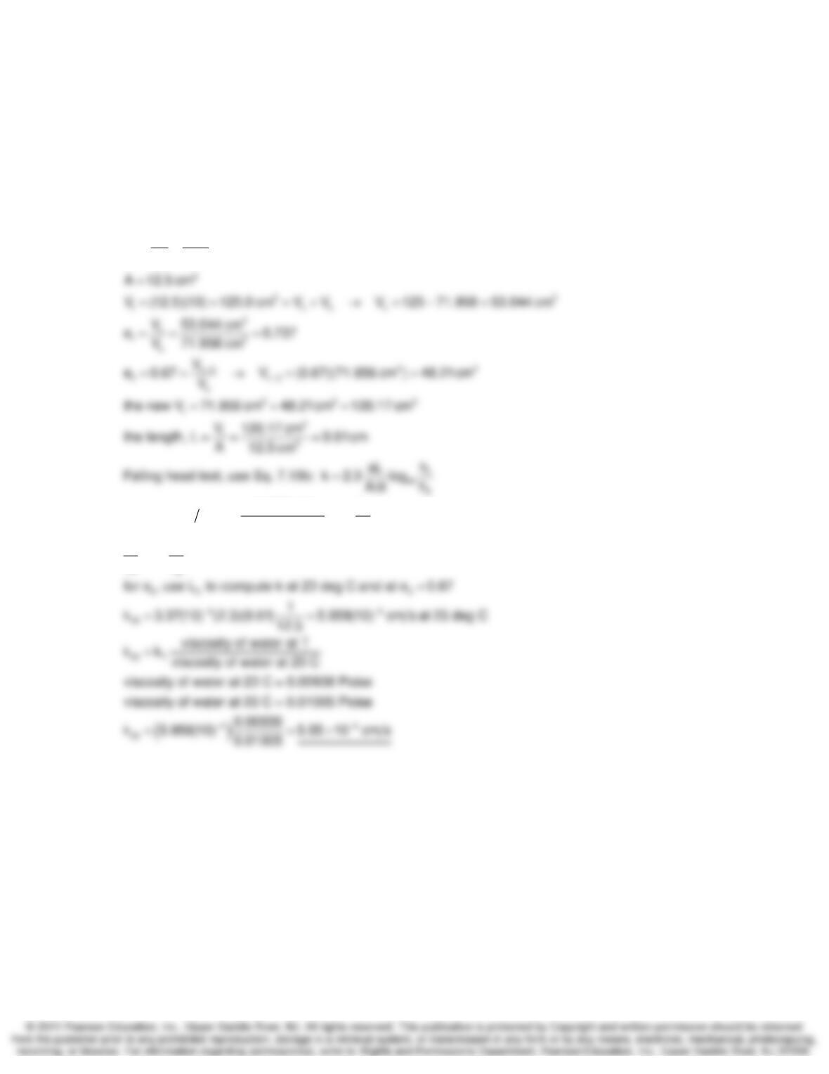
If all other items remain the same, k will decrease if e decreases because the
sample with the lower e is more dense.
Fluid Flow in Soils and Rock Chapter 7
7-9. A falling-head permeability test on a specimen of fine sand 12.5 cm2 in area and 10 cm long
gave a k of 6.2 x 10⁻⁴ cm/s. The dry mass of the sand specimen was 195 g and
ρ
s was 2.71
Mg/m3. The test temperature was 23°C. Compute the coefficient of permeability of the sand for a
void ratio of 0.67 and the standard temperature of 20°C. (After A. Casagrande.)
SOLUTION:
1
3
s
s
s
Compute e
M195
V 71.956 cm
2.71
== =
ρ
41
10
2
2
4
1
10
h
(a)(10 cm)
6.2(10) cm s 2.3 log h
(12.5 cm )( t)
h
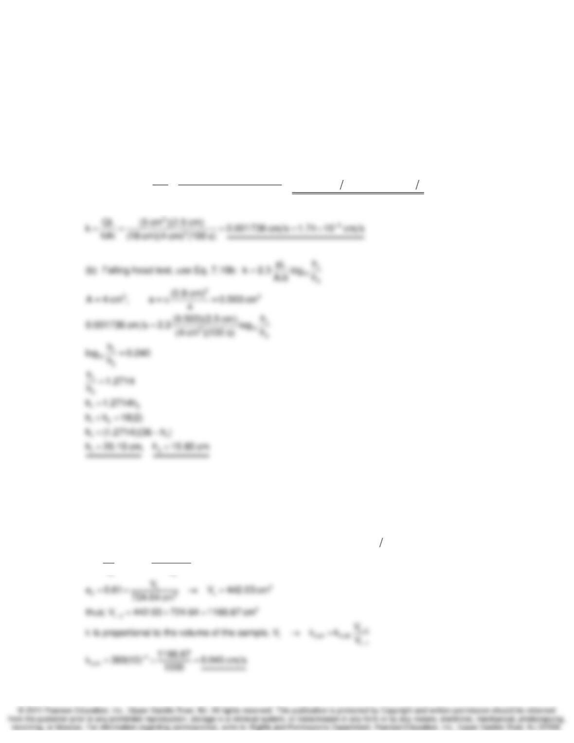
alog 3.37(10) values on the left sid
th
−
−
=Δ
=→
Δ
e do not change
Fluid Flow in Soils and Rock Chapter 7
7-10. A constant head permeability test is performed on a soil that is 2 cm x 2 cm square and 2.5
cm long. The head difference applied during the test is 18 cm, and 5 cm3 is collected over a time
of 100 sec. (a) Compute the permeability based on these test conditions and results. (b) A falling
head test is to be done on the same soil specimen in the same time (t1 – t2 = 100 s) and the
standpipe diameter is 0.8 cm. If the average head during the test should be 18 cm what are h1
and h2?
SOLUTION:
3
3
2
2
QL (405 cm )(17.5 cm)(4)
(a) Eq. 7.9 : k 0.00862 cm s 8.62 10 cm s
hAt (38cm) (17.5cm) (90s)
A224cm
−
== = =×
π
=×=
7-11. The coefficient of permeability of a clean sand was 389 x 10-4 cm/s at a void ratio of 0.38.
Estimate the permeability of this soil when the void ratio is 0.61.
SOLUTION:
34
tvs0.38
3
s
v
1ss
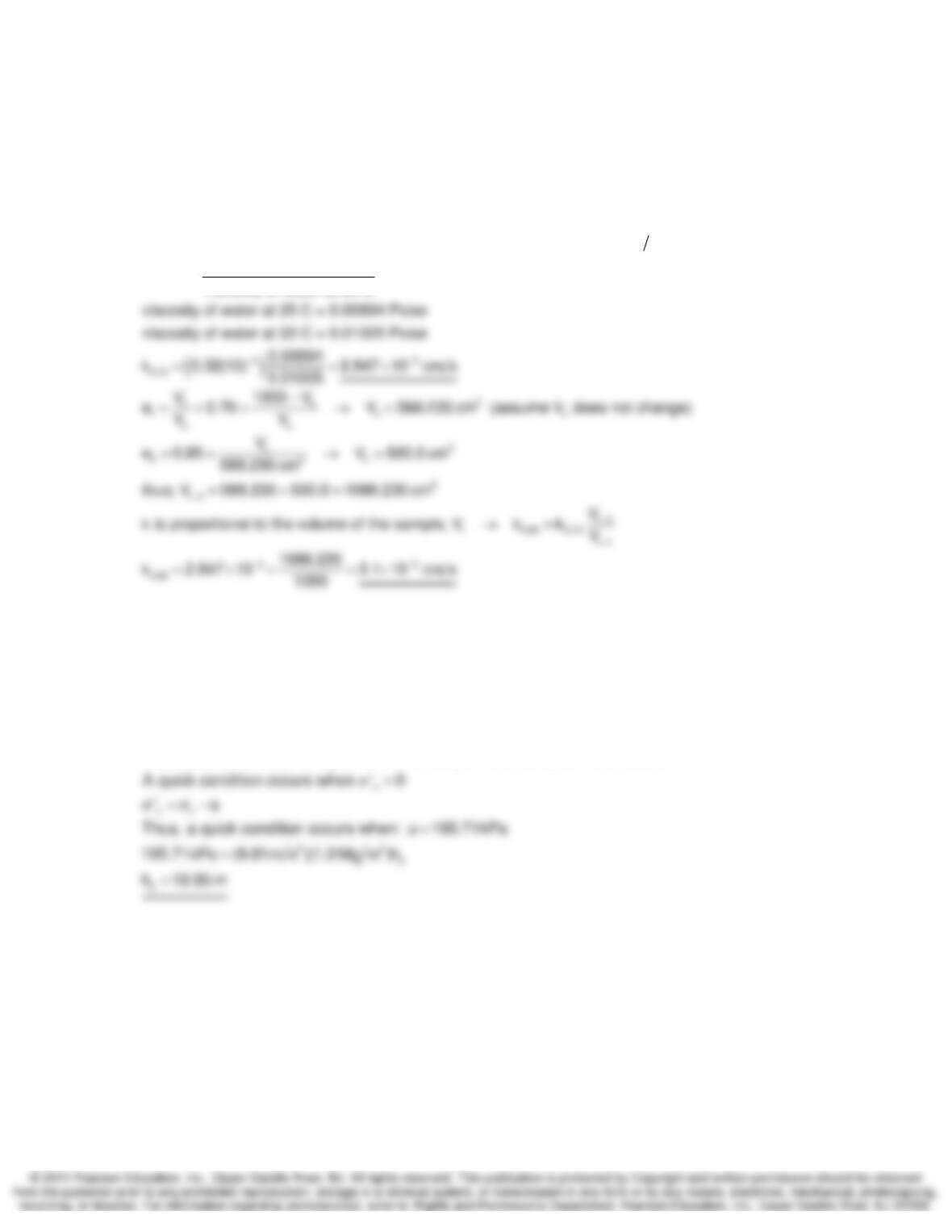
Assumptions : S 100%, V 1000 cm V V , k 389(10) cm s
1000 V
V
e 0.38 V 724.64 cm (assume V does not change)
VV
−
===+=
−
== = → =
Fluid Flow in Soils and Rock Chapter 7
7-12. Permeability tests on a soil supplied the following data:
e1 = 0.70, Temp1 = 25 C, k1 = (0.32)-4 cm/s
e2 = 1.10, Temp2 = 40 C, k1 = (1.80)-4 cm/s
Estimate the coefficient of permeability at 20°C and a void ratio of 0.85. (After Taylor, 1948.)
SOLUTION:
34
t 1 v s 0.70
0.70 T
Assumptions : S 100%, V 1000 cm V V , k 0.32(10) cm s
viscosity of water at T
kk
viscosity of water at 20 C
−
−
===+=
=
7-13. For the initial case in Problem 6.33, compute the head of water required at the top of the
silty clay layer to cause a quick condition.
SOLUTION:
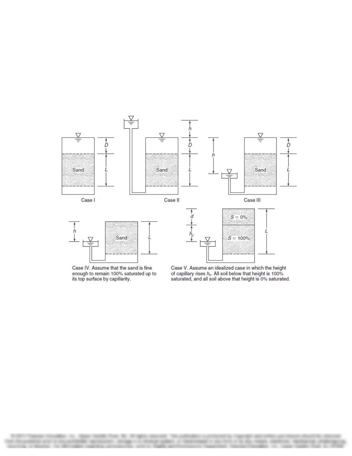
vv
Initial conditions at 10 m: 195.71kPa, ‘ 146.66 kPa, u 49.05 kPa
σ= σ = =
Fluid Flow in Soils and Rock Chapter 7
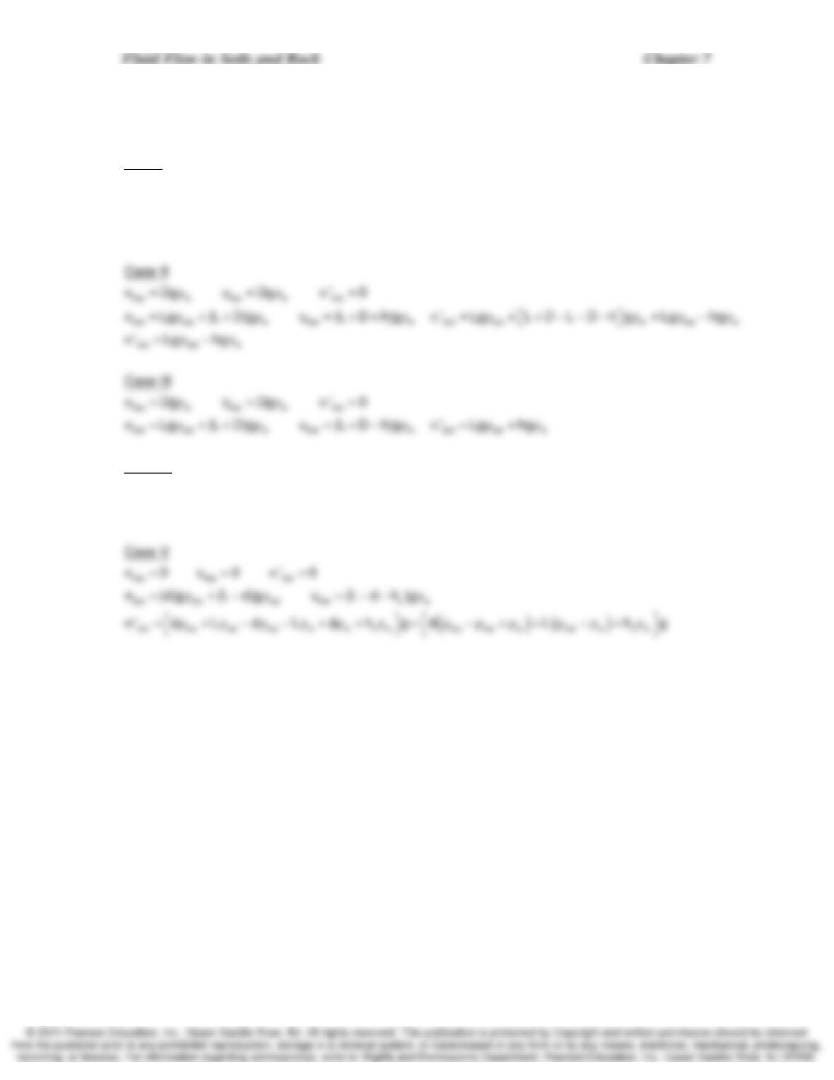
7-14. Sand is supported on a porous disc and screen in vertical cylinder, as shown in Fig. P7.14.
These are equilibrium conditions. (a) For each of the five cases, plot the total, neutral, and
effective stresses versus height. These plots should be approximately to scale. (b) Derive
formulas for those three stresses in terms of the dimensions shown and e,
ρ
s, and pw for each
case at both the top and bottom of the sand layer. For case IV, assume the sand is 100%
saturated to the upper surface by capillarity. For case V, assume the sand above level hc is
completely dry and below is completely saturated. (After A. Casagrande.)
continued next page
7-14 SOLUTION:
top w top w top
bot sat w bot w bot sat w w w sat w
bot
Case I
Dg u Dg ‘ 0
Lg Dg u (L D)g ‘ L D L D g Lg( ) Lg ‘
‘Lg‘
σ= ρ = ρ σ =
σ = ρ + ρ = + ρ σ = ρ +ρ−ρ−ρ = ρ −ρ = ρ
⎡⎤
⎣⎦
σ=ρ
top top top
bot sat bot w bot sat w
Case IV
0u0 ‘0
Lg u (Lh)g ‘ Lg (Lh)g
σ= = σ =
σ=ρ =−ρσ=ρ−−ρ
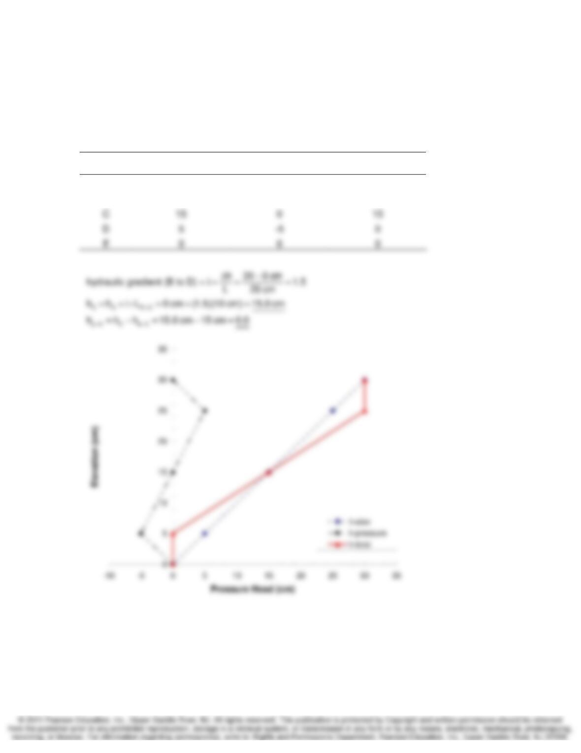
Fluid Flow in Soils and Rock Chapter 7
7-15. Given the soil cylinder and test setup of Example 7.4, with actual dimensions as follows:
AB = 5 cm, BC = 10 cm, CD = 10 cm, and DE = 5 cm. Calculate the pressure, elevation, and
total heads at points A through E in cm of water, and plot these values versus elevation.
SOLUTION:
Establish the datum at elevation corresponding to point E.
Point
Elevation Head, z
(cm)
Pressure Head, hp
(cm)
Total Head, h
(cm)
A 30 0 30
B 25 5 30
Fluid Flow in Soils and Rock Chapter 7
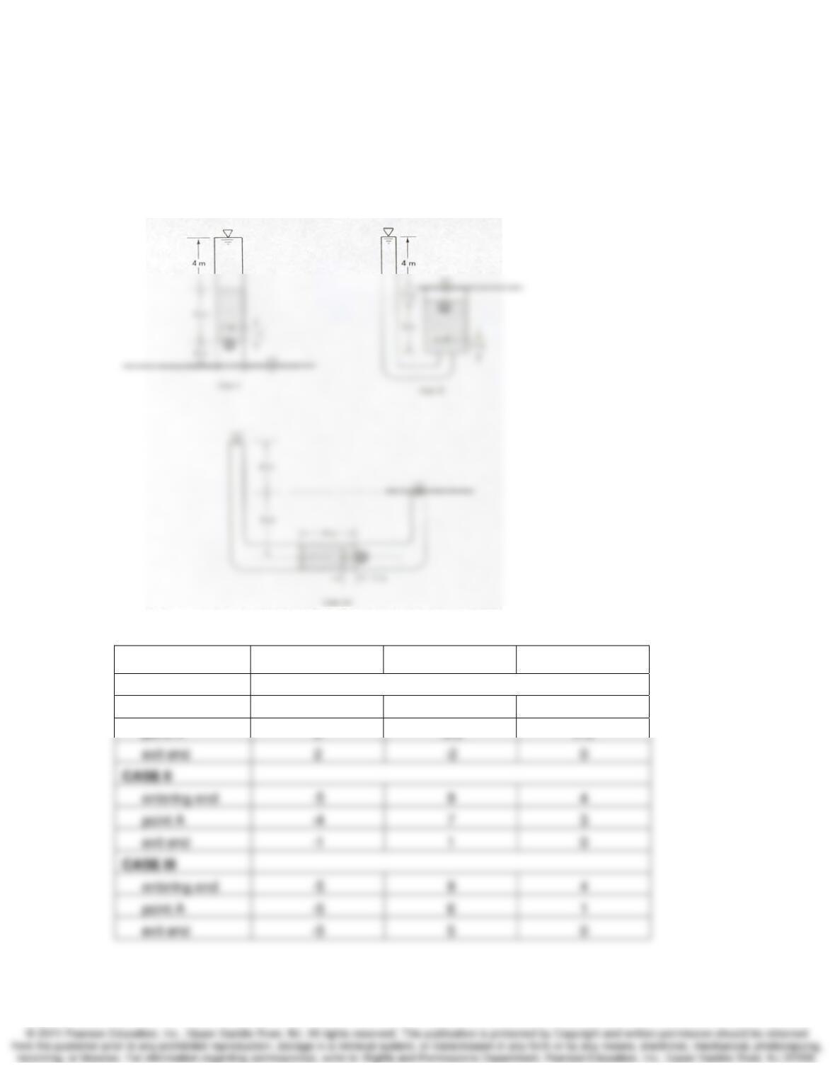
7-16. For each of the cases I, II, and III of Fig. P7.16, determine the pressure, elevation, and total
head at the entering end, exit end, and point A of the sample. (After Taylor, 1948.)
SOLUTION:
For this solution, the datum is located at the tailwater elevation shown by the dashed line in the
sketch. The exit end of the sample is the end closest to the smiley face symbol.
Elevation Head, z Pressure Head, hp Total Head, h
CASE I
entering end 6 4 10
point A 3 -0.5 2.5
Fluid Flow in Soils and Rock Chapter 7
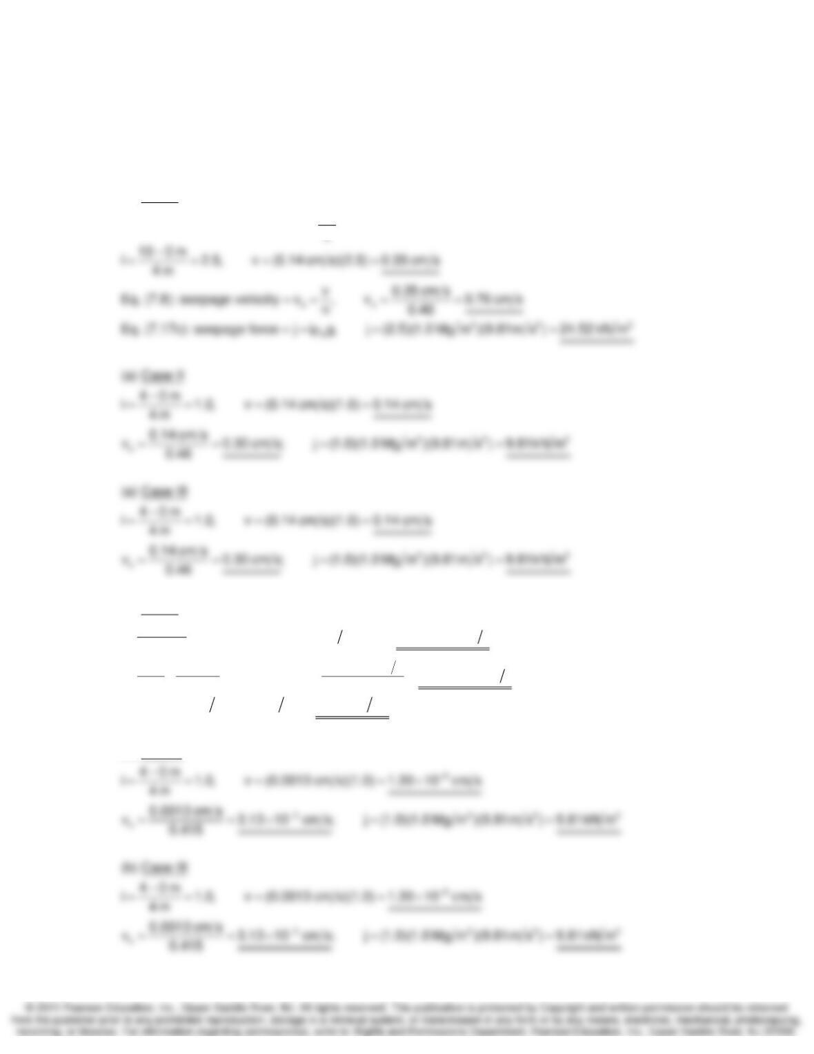
7-17. For each of the cases shown in Fig. P7.16, determine the discharge velocity, the seepage
velocity, and the seepage force per unit volume for (a) a permeability of 0.14 cm/s and a porosity
of 46% and (b) a permeability of 0.0013 cm/s and a void ratio of 0.71. (After Taylor, 1948.)
SOLUTION:
(a) Case I
h
Eq. (7.1): hydraulic gradient i , Eq. (7.2): discharge velocity v ki
L
Δ
== = =
3
3
s
32
(b) Case I
10 0 m
i 2.5, v (0.0013 cm s)(2.5) 3.25 10 cm s
4m
e 0.71 0.00325 cm s
n= = =0.415, v 7.83 10 cm s
1 e 1 0.71 0.415
j (2.5)(1.0 Mg m )(9.81m s ) 24.52 kN
−
−
−
== = =×
==×
++
==
3
m
(b) Case II