From Eq. (1)
Problem 6.56
A Rankine oval is formed by combining a source-sink pair, each having a strength of
2
ft
s
36
and separated by a distance of ft12 along the x axis, with a uniform velocity of ft
s
1
0 (in the
positive x direction). Determine the length and thickness of the oval.
Solution 6.56
1
2
1
lm
aUa
π
=+
(1)
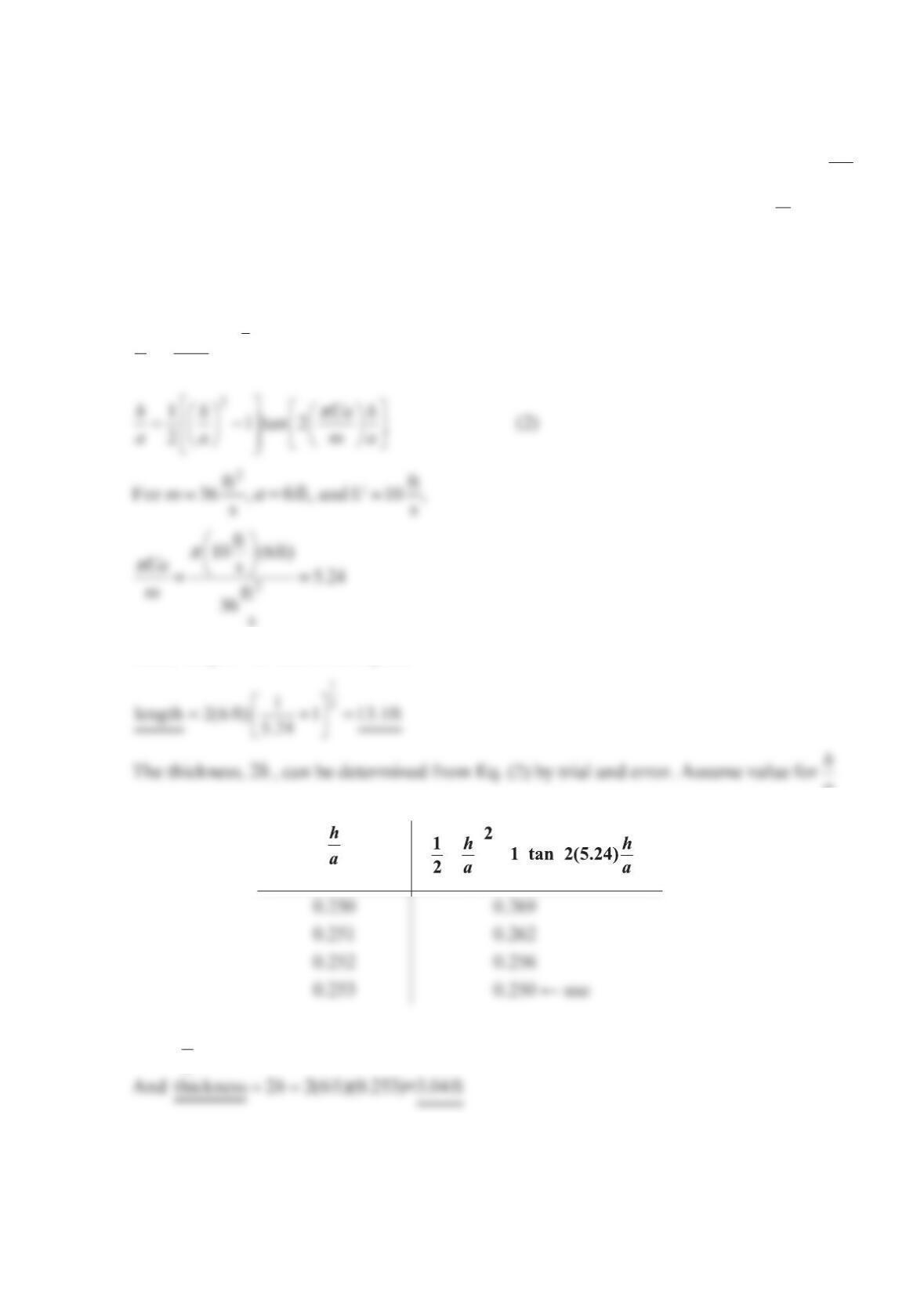
Thus, length 2l= and from Eq. (1)
a
and compare with right-hand side of Eq. (2) (see the table below).
−
Thus, 0.253
h
a≈
Problem 6.57
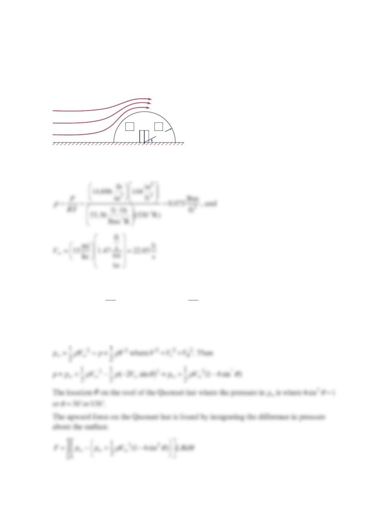
A -mph15 wind flows over a Quonset hut having a radius of ft12 and a length of ft60 , as
shown in the figure below. The upstream pressure and temperature are equal to those inside
the Quonset hut: psia
1
4.696 and 70 °F. Estimate the upward force on the Quonset hut.
Find the location
θ
on the roof of the Quonset hut where the pressure is
p
∞
.
Solution 6.57
The air density is found by the ideal gas law.
The velocity components for flow about a circular cylinder are given by equations:
2
2
cos 1
r
R
V
Vr
θ
∞
=−
and
2
2
sin 1 R
VV r
θ
θ
∞
=+
On the cylinder surface, r = R and 0
r
V
=, 2sinVV
θ
∞∞
=−
Bernoulli’s equation gives the pressure distribution over the exterior of the hut,
p
∞
, T
∞
p
∞
, T
∞
V
∞
12 ft
θ
22 2
00
111cos2
(1 4 sin ) 1 4
222
F V LR d V LR d
ππ
θ
ρ
θ
ρ
θ
∞∞
−
=− − =− −
ρ
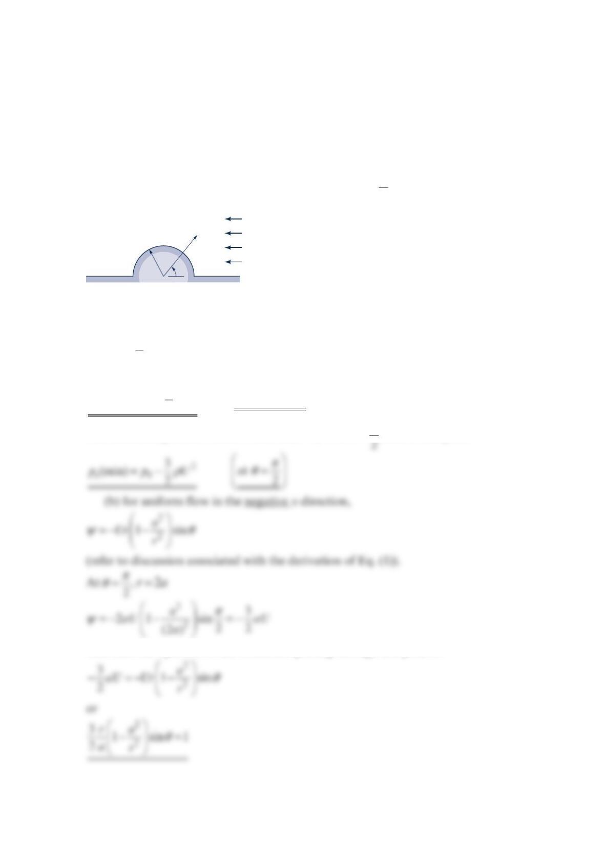
Problem 6.58
An ideal fluid flows past an infinitely long, semicircular “hump” located along a plane
boundary, as shown in the figure below. Far from the hump, the velocity field is uniform,
and the pressure is 0
p
. (a) Determine expressions for the maximum and minimum values of
the pressure along the hump, and indicate where these points are located. Express your
answer in terms of
ρ
,
U
, and 0
p
. (b) If the solid surface is the
0
ψ
= streamline, determine the
equation of the streamline passing through the point 2
π
θ
=, 2r
a
=.
Solution 6.58
(a) On the surface of the hump,
22
s0
1(1 4 sin )
2
pp U
ρ
θ
=+ − (1)
The maximum pressure occurs where sin
0
θ
=, or at
0
θ
=,
π
, and at these points
2
s0
1
(max) 2
p
pU
ρ
=+ (
a
t 0 and
θ
π
=)
The minimum pressure occurs where sin
1
θ
=, or at 2
π
θ
=, and at this point
And thus the equation of the streamline passing through this point is
r
a
U
,
p0
θ
p
θ
a

Problem 6.59
Assume that the flow around the long circular cylinder of the figure below is nonviscous
and incompressible. Two pressures, 1
p
and 2
p
, are measured on the surface of the cylinder,
as illustrated. It is proposed that the free-stream velocity,
U
, can be related to the pressure
difference 12
p
pp
Δ
=−
by the equation
p
U
C
p
Δ
=
where
p
is the fluid density. Determine the value of the constant
C
. Neglect body forces.
Solution 6.59
Since 1
p
is the stagnation pressure,
Thus, from Eq. (1)
222
12 2
11 3
(3 )
22 2
p
pV U U
g
γ
ρρ
−= = =
p
U
a
60°
p
1
p
2
x
y
U
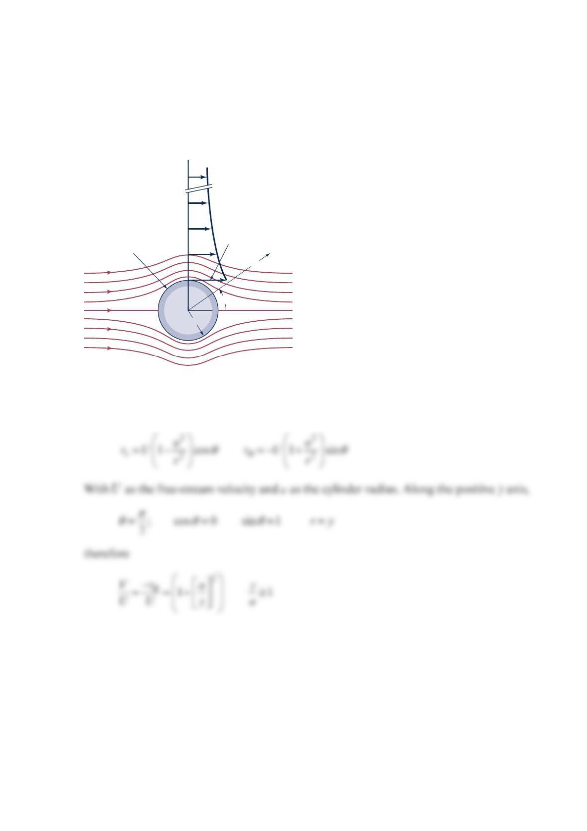
Problem 6.60
Consider the steady potential flow around the circular cylinder as shown in the figure be-
low. On a plot show the variation of the magnitude of the dimensionless fluid velocity,
/,
V
U along the positive
y
axis. At what distance,
/
y
a (along the
y
axis), is the velocity with-
in
1
%
of the free-stream velocity?
Solution 6.60
The velocity components are given by Eqs. (6.114) and (6.115)
a
r
U
θ
Ψ
= 0
2
U
y
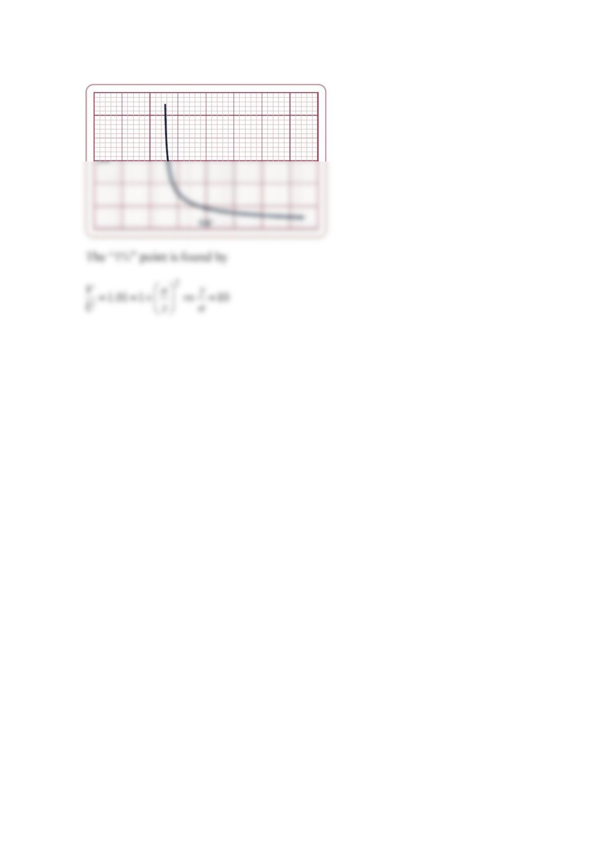
The following plot was made using Microsoft® Excel®
Dimensionless Velocity Above
the Crest of a Circular Cylinder
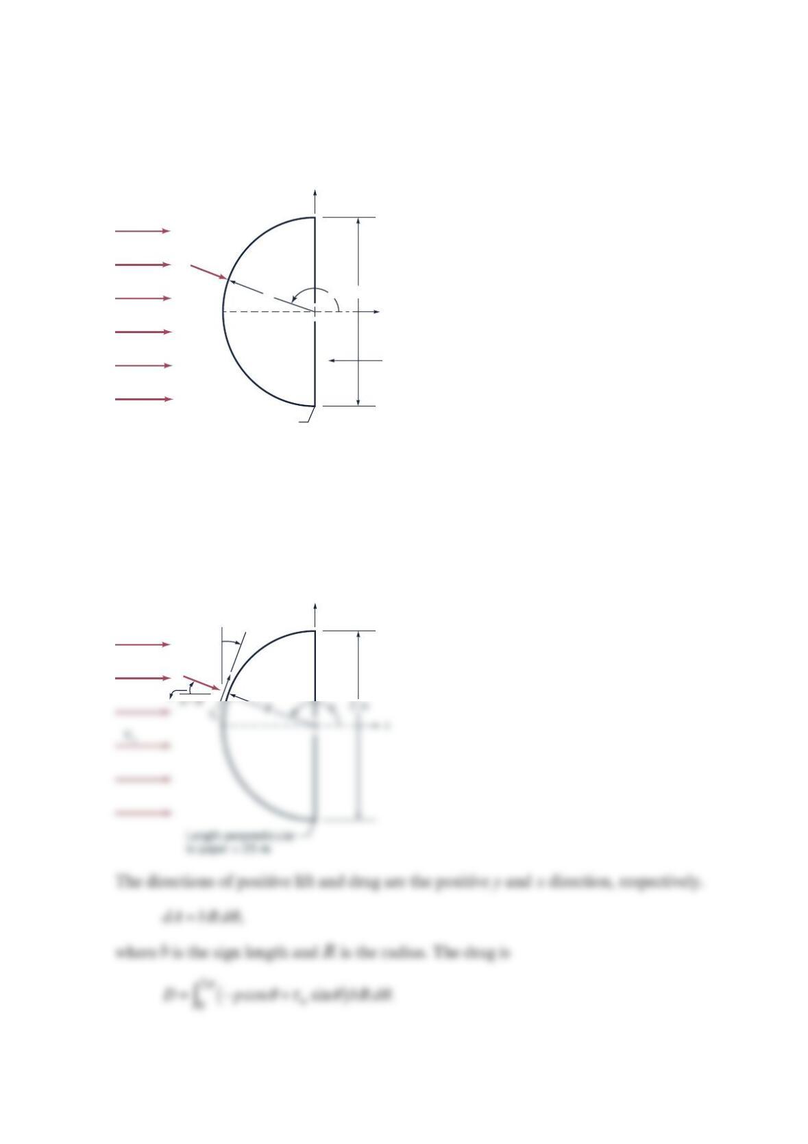
Problem 6.61
A highway sign has the shape of a half-cylinder with radius
1.0
m
and length 25.0 m. A
rearward
1
0 km/hr wind is blowing over the sign as shown in the figure below.
The pressure on the flat face is constant and equal to the pressure at the corner. Find the
force on the sign. Neglect end effects.
Solution 6.61
Sign having shape of half-cylinder, as shown in the figure below.
x
y
V
∞
2 m
Length Perpendicular
to paper = 25 m
R
p
Wind
Message here
θ
y
p
Wind
–
θ
π
Recognizing that the drag on the top half equals the drag on the bottom half gives
Thus,
Integrating, we obtain
Next find the lift. Recognizing that
d
AbRd
θ
= and that there is no lift component on the
flat face, we have
Integrating yields
()
so
0.L=
Comments The zero lift should not be surprising, because the vertical component of the
Problem 6.62
Air at 25 °C flows normal to the axis of an infinitely long cylinder of
1
.0 m radius. The cyl-
inder is rotating at rad
1
0s, and the approach velocity is km
1
00 hr . Find the maximum and
minimum pressures on the cylinder surface. Assume potential flow.
Solution 6.62
For 25 C , 3
kg
1.19 m
ρ
=. Applying Bernoulli’s equation to the air gives
Then
2
2
sin sin 2 sin
22
rR rR rR
R
VVV V
rrR
r
θ
ψθθ θ
ππ
∞∞ ∞
===
∂ΓΓ
=− =− + + =− −
∂
,
and
The location of the minimum and maximum pressures is found by setting 0
p
θ
∂=
∂ and solv-
ing for
θ
. This gives
p
Since 2
22RU R
ππ
ω
Γ
==,
Then
2
23
kg m
(1.19 )(27.78 )
s
m
101300 Pa+ 101760 Pa
22
V
p
ρ
∞
∞+= = ,
22
(2 sin )
22
R
ppV V R
ρρ θω
∞∞
=+ − +
Then
max 101760 Pap=at 10.37
θ
=− ,
θ
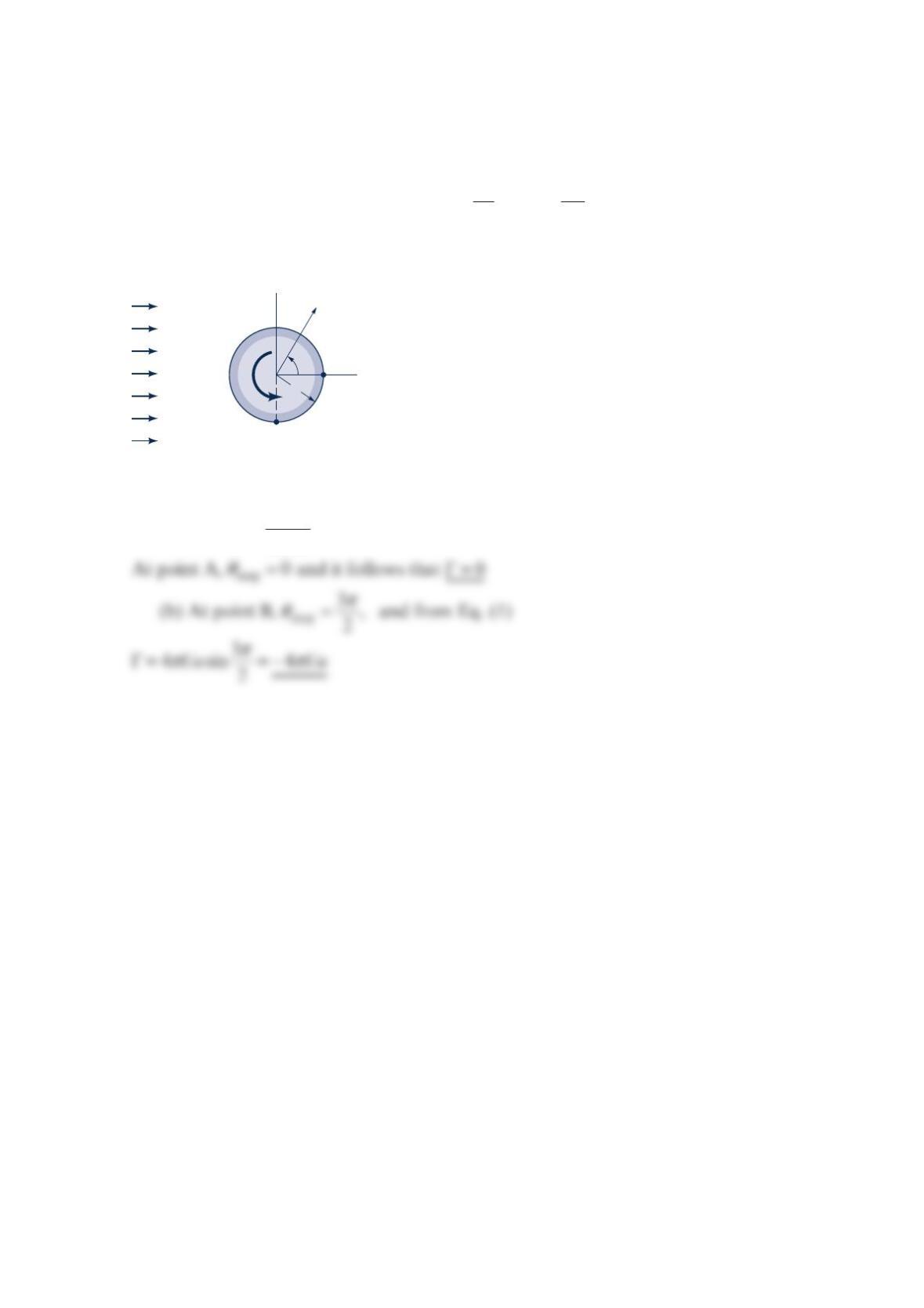
Problem 6.63
The velocity potential for a cylinder (the figure below) rotating in a uniform stream of
fluid is
2
2
1cos
2
a
Ur r
φ
θθ
π
Γ
=+ +
where
Γ
is the circulation. For what value of the circulation will the stagnation point be lo-
cated at: (a) point A; (b) point B?
Solution 6.63
(a) sin 4
stag Ua
θπ
Γ
= (1)
U
r
y
x
A
B
θ
a
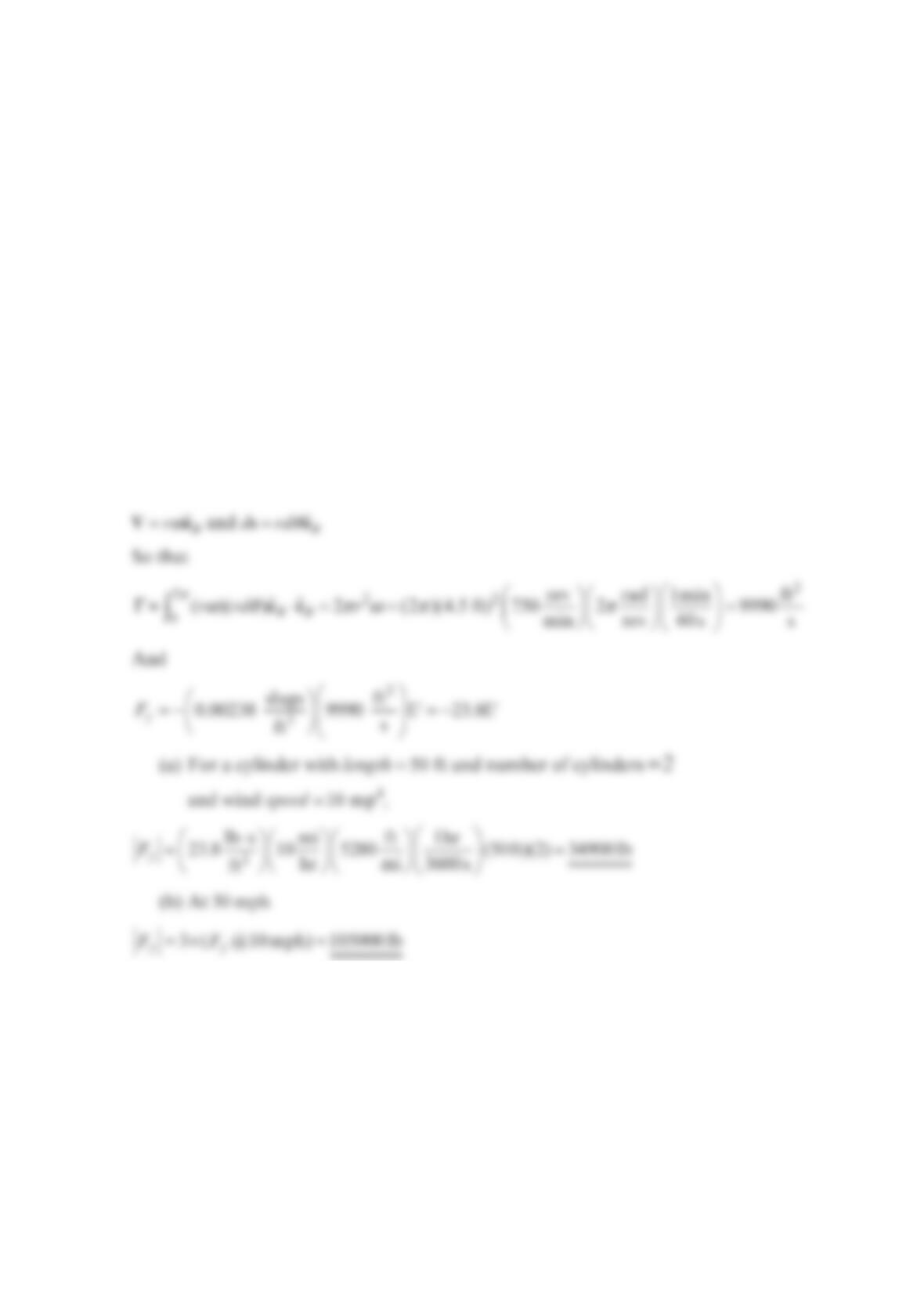
Problem 6.64
Determine the magnitude of the total force developed by the two rotating cylinders on the
Flettner “rotor-ship” due to the Magnus effect. Assume a wind-speed relative to the ship of
(a)
1
0 mp
h
and (b)
3
0 mph. Each cylinder has a diameter of
9
ft, a length of 50 ft, and ro-
tates at 750 rev/min. Use the equation y
F
U
ρ
=− Γ
and calculate the circulation by assuming
the air sticks to the rotating cylinders. Note: This calculated force is at right angles to the
direction of the wind and it is the component of this force in the direction of motion of the
ship that gives the propulsive thrust. Also, due to viscous effects, the actual propulsive
thrust will be smaller than that calculated from the equation y
F
U
ρ
=− Γ
, which is based on
inviscid flow theory.
Solution 6.64
y
F
U
ρ
=− Γ
(force per unit length)
Vs
Γ
=d
On the cylinder surface
s
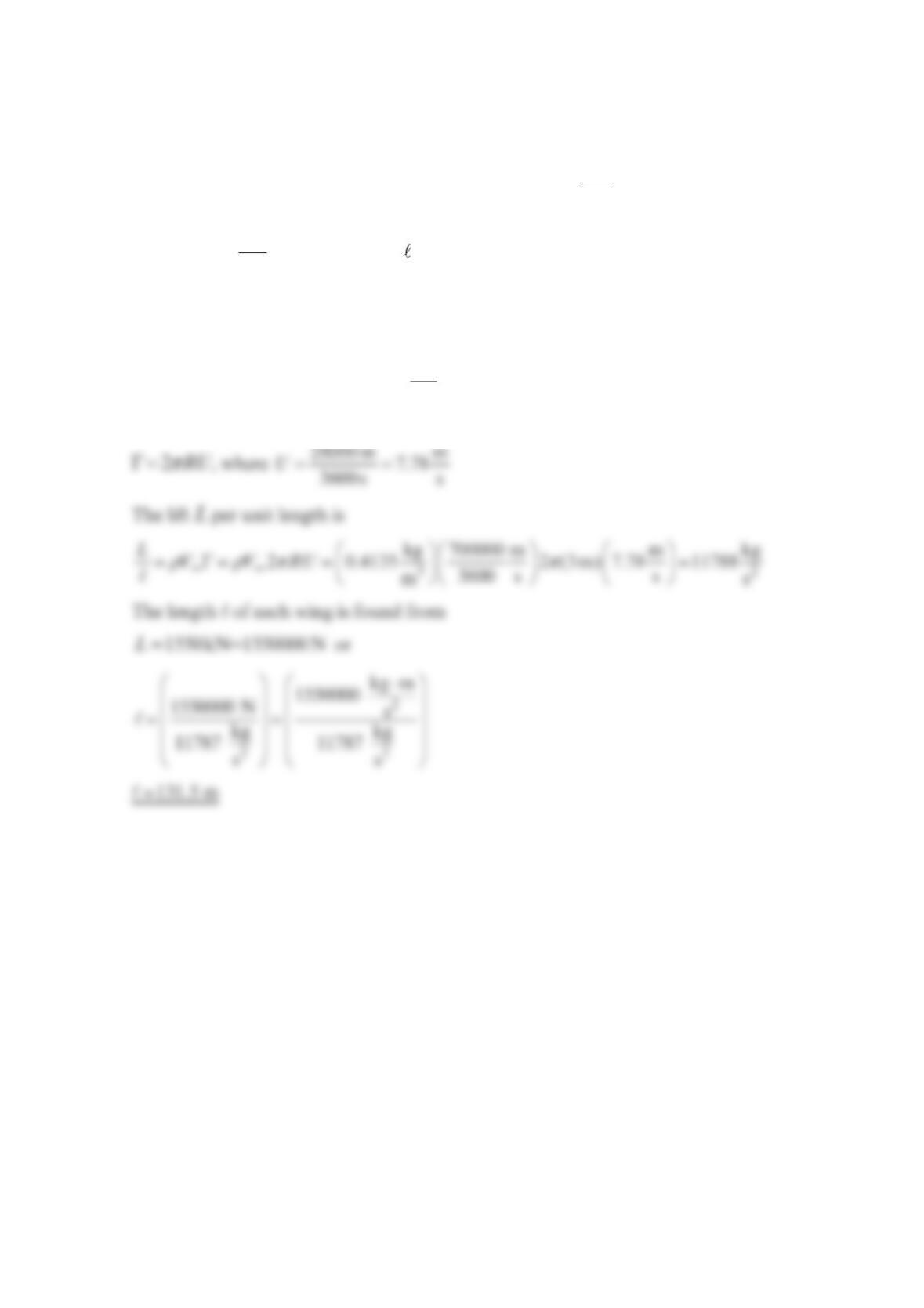
Problem 6.65
Consider the possibility of using two rotating cylinders to replace the conventional wings
on an airplane for lift. Consider an airplane flying at km
7
00 hr through the Standard Atmos-
phere at
1
0,000 m. Each “wing cylinder” has a 3.0-m radius. The surface velocity of each
cylinder is km
2
8hr . Find the length of each wing to develop a lift of
1550 k
N
. Assume po-
tential flow and neglect end effects.
Solution 6.65
At 10,000 m , the density is 3
kg
0.4135 m. The equation for lift and circulation about a rotat-
ing cylinder are
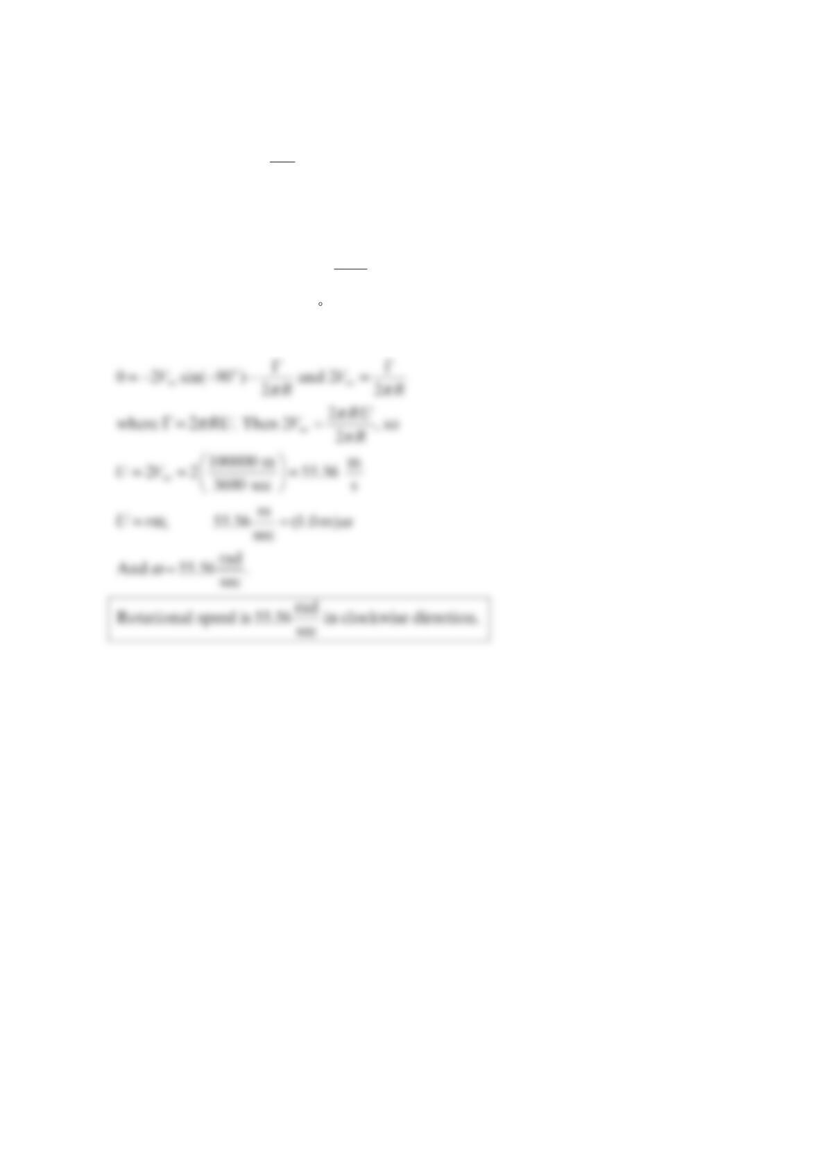
Problem 6.66
Air at 25 °C flows normal to the axis of an infinitely long cylinder of
1
.0 m radius. The ap-
proach velocity is km
1
00 hr . Find the rotational velocity of the cylinder so that a single stag-
nation point occurs on the lower-most part of the cylinder. Assume potential flow.
Solution 6.66
Equation )2sin
2
rR
V
VR
θ
θπ
=∞
Γ
=− − gives the velocity at the surface of the cylinder.
The stagnation point 90
θ
=− is found by setting 0
V
θ
=
so
Problem 6.67
Determine the shearing stress for an incompressible Newtonian fluid with a velocity distri-
bution of =−+ −
.
Solution 6.67
The shearing stress for an incompressible* Newtonian fluid is
ττ µ
∂∂
== +
∂∂
Thus,
τµ µ
=+=
τµ
=+=
and
Problem 6.68
The two-dimensional velocity field for an incompressible Newtonian fluid is described by
the relationship
23 2 3
ˆˆ
(12 6 ) (18 4 )xy x x y y=−+−V
where the velocity has units of m/s when x and
y
are in meters. Determine the stresses xx
σ
,
yy
σ
, and xy
τ
at the point 0.5
m
x=,1.0 m
y
= if pressure at this point is 6 kP
a
and the fluid is
glycerin at 20 °C. Show these stresses on a sketch.
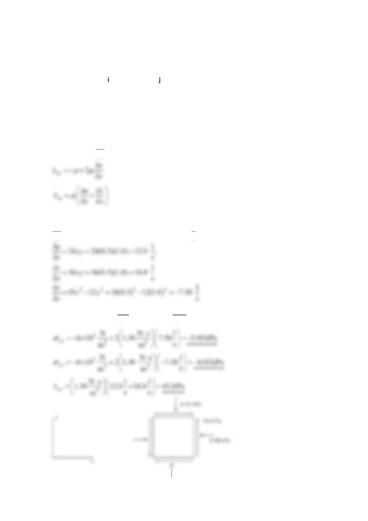
Solution 6.68
2
xx
u
px
τµ
∂
=− + ∂
For the given velocity distribution, with 0.5
m
x= and 1.0 m
y
=:
22 2 2 1
12 18 12(1.0) 18(0.5) 7.50 s
uyx
x
∂=−= − =
∂,
Thus, for 3
2
N
610m
p=× and 2
Ns
1.50 m
µ
⋅
=,
y
Problem 6.69
The velocity of a fluid particle moving along a horizontal streamline that coincides with the
axisx in a plane, two-dimensional, incompressible flow field was experimentally found to
be described by the equation 2
ux=. Along this streamline, determine an expression for
(a) the rate of change of the
v
component of velocity with respect to
y
, (b) the acceleration
of the particle, and (c) the pressure gradient in the x direction. The fluid is Newtonian.
Solution 6.69
(a) From the continuity equation,
Also, Eq. (1) can be integrated with respect to
y
obtain
2dv xd
y
=−
or
2()vxyfx=− +
Since the -axisx is a streamline, 0v= along this axis and therefore ( ) 0
f
x= so that
Along -axisx, 0
y
=, and therefore 0
y
a
=. Thus,
3ˆ
2x=a
(c) With 0
x
g=,
p
p