6.40: PROBLEM DEFINITION
Situation:
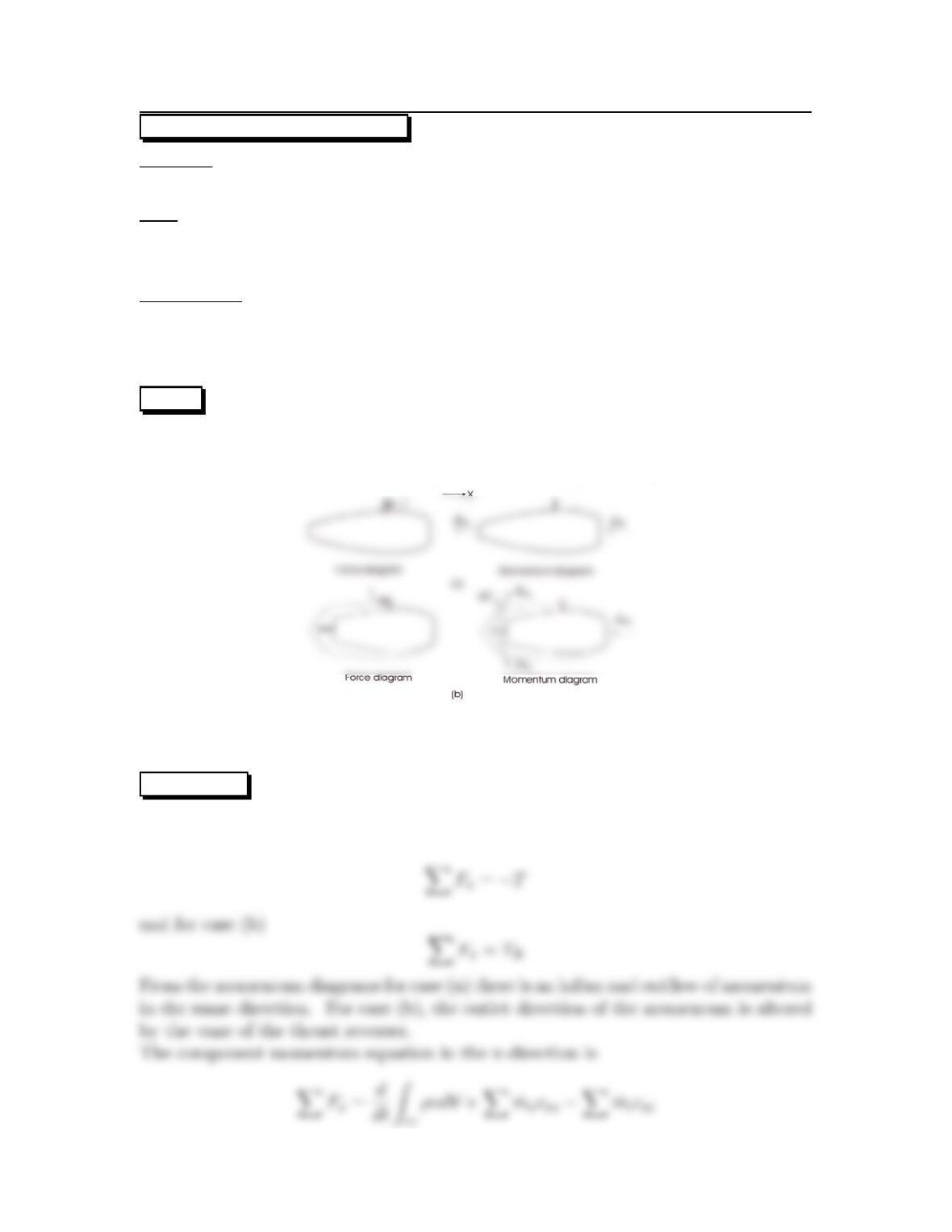
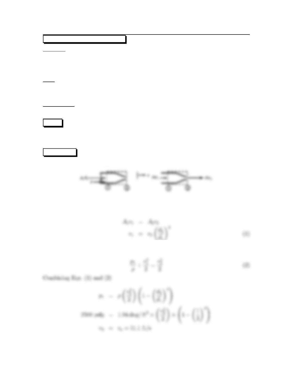
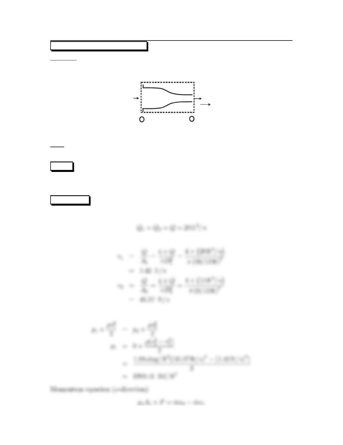
A clam shell thrust reverser is deployed on an aircraft engine.
Find:
(a) The thrust under normal operation.
(b) the reverse thrust.
Assumptions:
Engine is stationary.
Exit gas velocity unchanged at deployment.
Pressure is atmospheric at exhaust plane.
PLAN
Apply the component momentum equation.
SOLUTION
The control volumes for both cases are shown in the diagram. For case (a) the sum
of the forces in the x-direction is
61
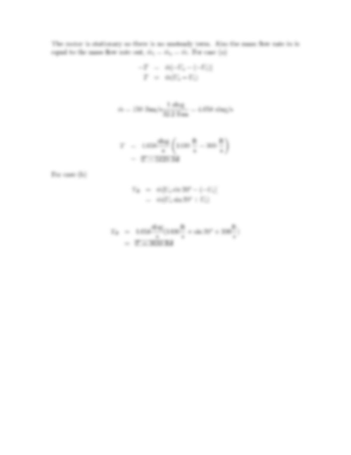
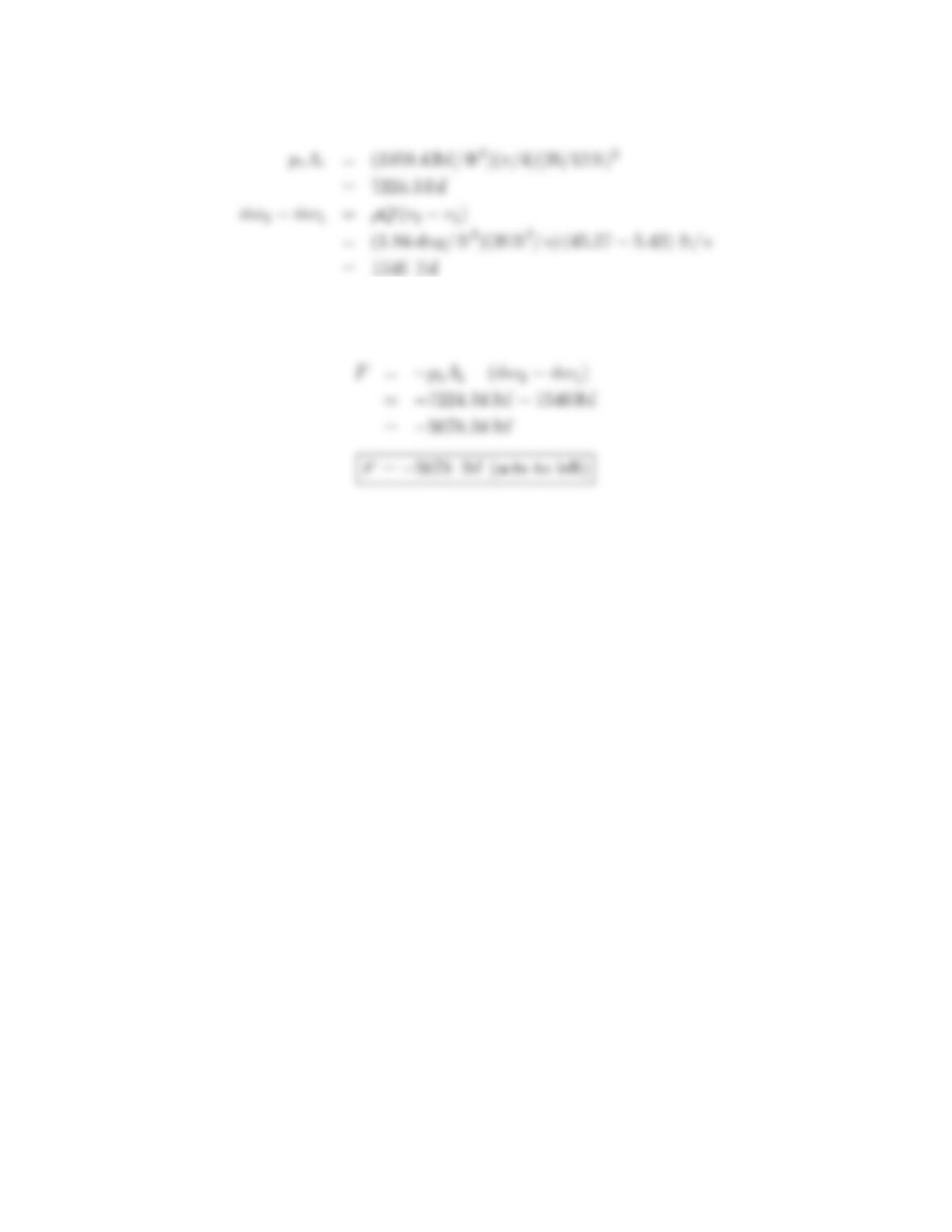
The mass flow rate is
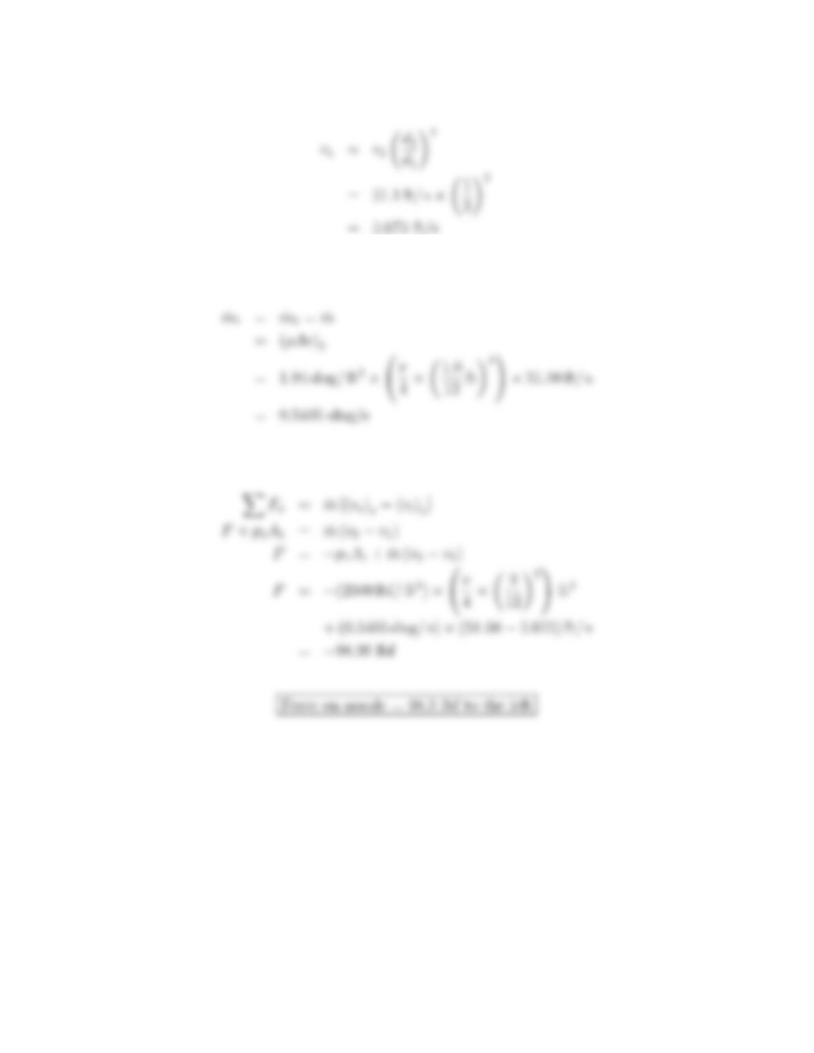
The thrust for case (a) is
The reverse thrust is
62
6.41: PROBLEM DEFINITION
Situation:
Information of fire hoses and nozzles
Find:
Information of operational conditions and typical hose sizes and nozzles.
SOLUTION
63
6.42: PROBLEM DEFINITION
Situation:
High speed water jets.
Find:
Estimate water speed for 60,000 psig pressure
Assumptions:
Inlet velocity is negligible and viscous effects are not important. Assume the exit
pressure is atmospheric
PLAN
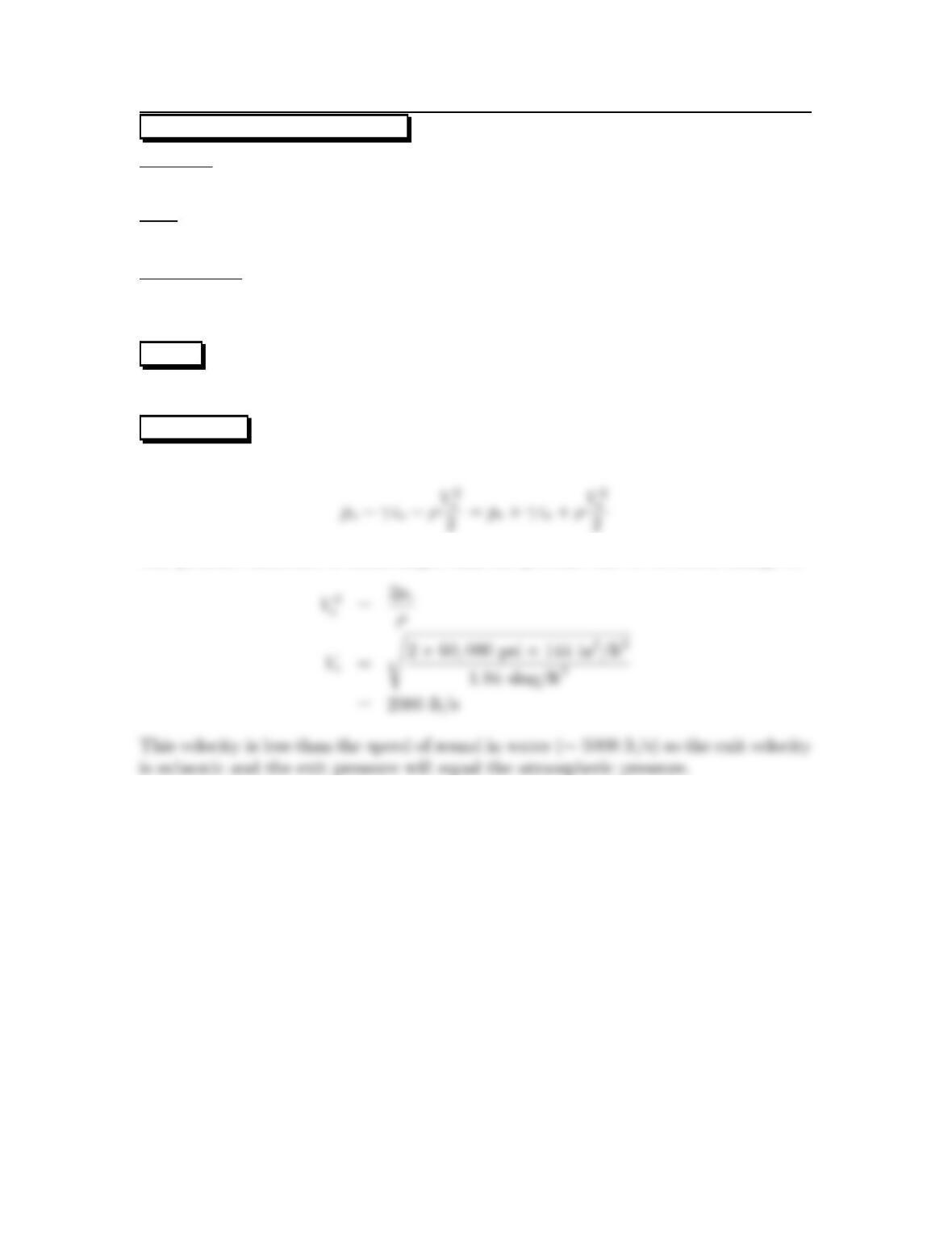
Apply the Bernoulli equation.
SOLUTION
The Bernoulli equation between the chamber and nozzle exit
The pressure difference is much larger than the pressure due to elevation change so
64
6.43: PROBLEM DEFINITION
Situation:
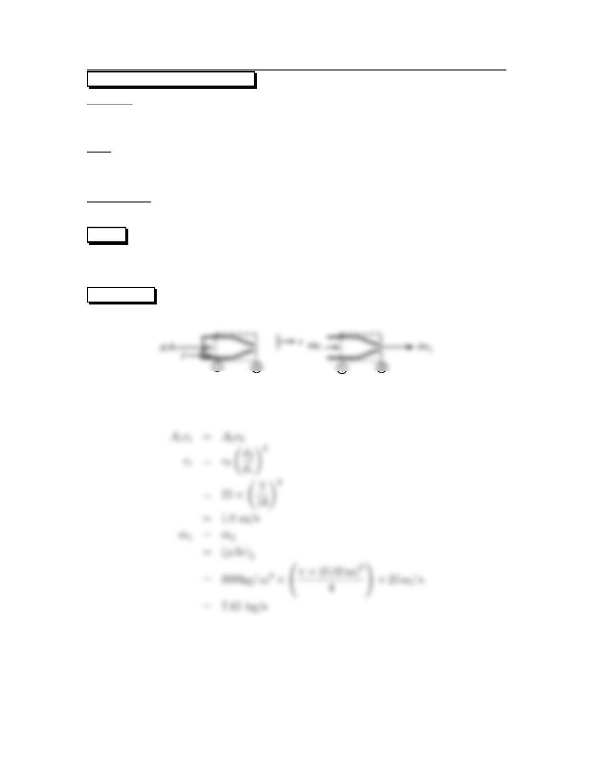
Water (60 oF) flows through a nozzle.
d1=3in,d2=1in..
p1=2500psfg, p2=0psfg
Find:
(a) Speed at nozzle exit: v2
(b) Force to hold nozzle stationary: F
Assumptions:
Neglect weight, steady flow.
PLAN
Apply the continuity equation, then the Bernoulli equation, and finally the momen-
tum equation.
SOLUTION
Force and momentum diagrams
Continuity equation
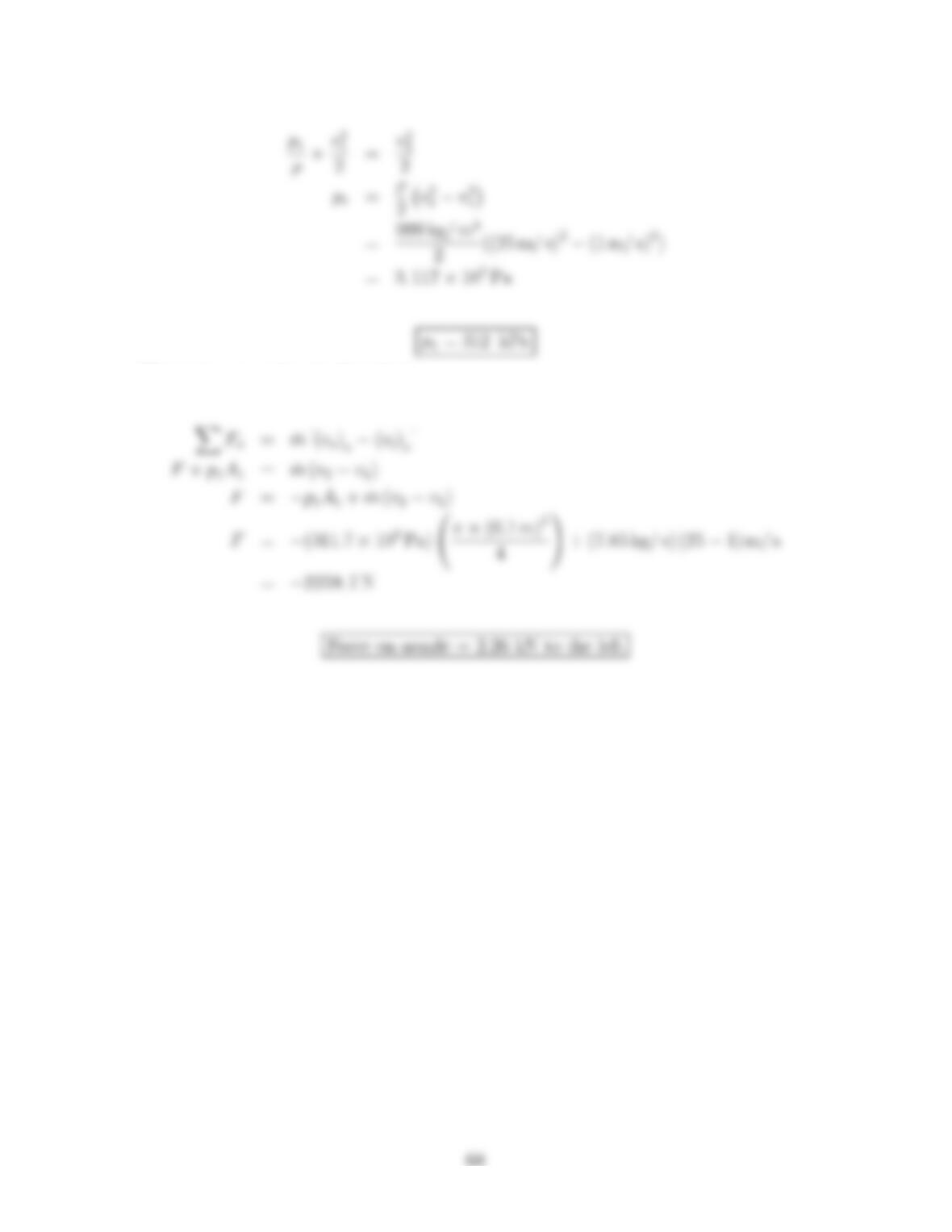
Bernoulli equation applied from 1 to 2
65
From Eq. (1)
Flow rate
Momentum equation (x-direction)
66
6.44: PROBLEM DEFINITION
Situation:
Water (15 oC) flows through a nozzle.
d1=10cm., d2=2cm., v2=25m/s, ρ=999kg/m3
Find:
(a)Pressure at inlet: p1
(b)Force to hold nozzle stationary: F
Assumptions:
Neglect weight, steady flow, p2=0kPa-gage.
PLAN
Apply the continuity equation, then the Bernoulli equation, and finally the momen-
tum equation.
SOLUTION
Force and momentum diagrams
Continuity equation
Bernoulli equation applied from 1 to 2
67
Momentum equation (x-direction)
6.45: PROBLEM DEFINITION
Situation:
Water flows through a converging nozzle–additional details are provided in the
problem statement.
12
x
v
1
v
2
Find:
Force at the flange to hold the nozzle in place: F
PLAN
Apply the Bernoulli equation to establish the pressure at section 1, and then apply
the momentum equation to find the force at the flange.
SOLUTION
Continuity equation (select a control volume that surrounds the nozzle).
Flow rate equations
Bernoulli equation
69
Calculations
Substituting numerical values into the momentum equation
70
6.46: PROBLEM DEFINITION
Situation:
Water flows through a converging nozzle–additional details are provided in the
problem statement.
Find:
Force at the flange to hold the nozzle in place: Fx
PLAN
Apply the Bernoulli equation, and then the momentum equation.
SOLUTION
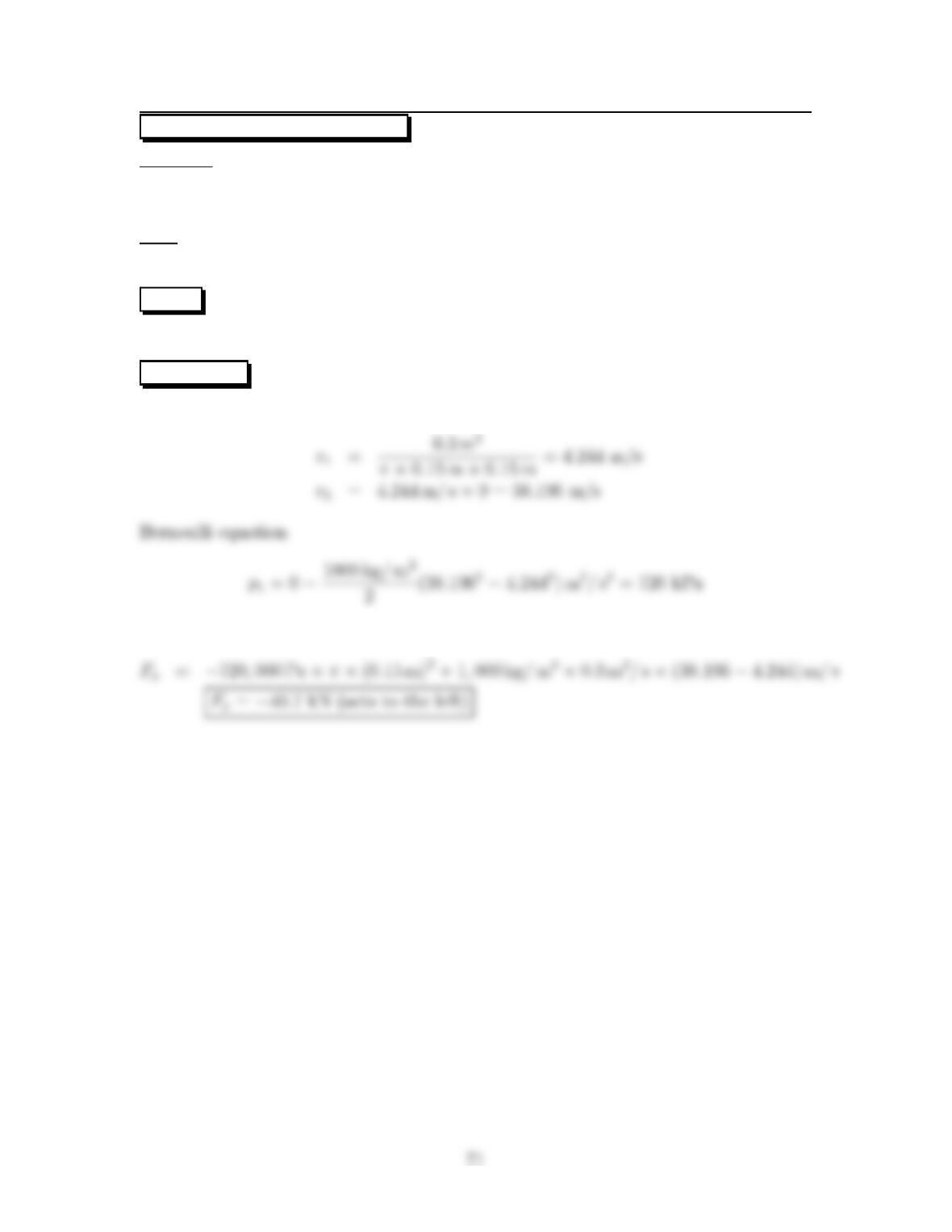
Velocity calculation
Momentum equation (x-direction)
6.47: PROBLEM DEFINITION
Situation:
Water flows through a nozzle with two openings–additional details are provided
in the problem statement
Find:
x-component of force through flange bolts to hold nozzle in place.
PLAN
Apply the Bernoulli equation, and then the momentum equation.
SOLUTION
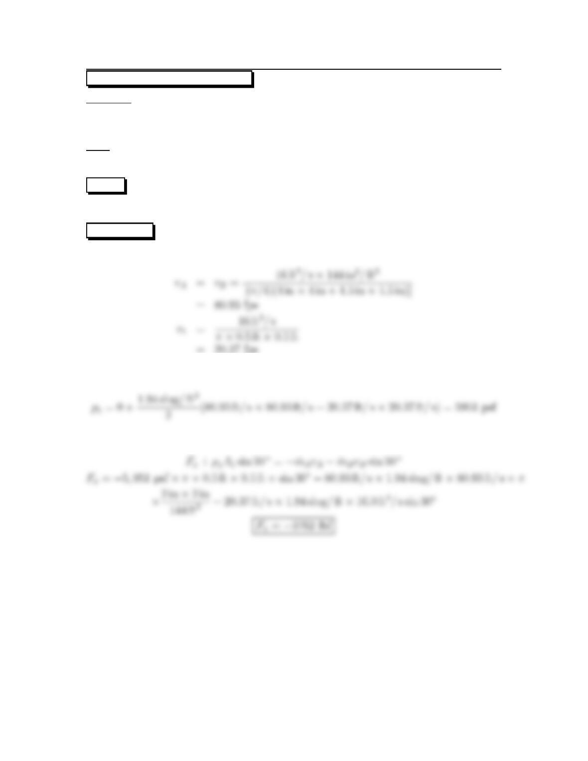
Velocity calculation
=20.37 fps
Bernoulli equation
Momentum equation (x-direction)
72
6.48: PROBLEM DEFINITION
Situation:
Water flows through a nozzle with two openings–additional details are provided
in the problem statement.
Find:
x-component of force through flange bolts to hold nozzle in place: Fx
PLAN
Apply the Bernoulli equation, and then the momentum equation.
SOLUTION
Velocity calculation
Bernoulli equation
Momentum equation (x-direction)
73
6.49: PROBLEM DEFINITION
Situation:
A rocket nozzle is connected to a combustion chamber.
Mass flow: ˙m=220kg/s. Ambient pressure: po=100kPa.
Nozzle inlet conditions: A1=1m
2,u
1=100m/s,p1=1.5MPa-abs.
Nozzle exit condition? A2=2m
2,u
2=2000m/s,p2=80kPa-abs.
Assumptions:
The rocket is moving at a steady speed.
Find:
Force on the connection between the nozzle and the chamber.
PLAN
Apply the momentum equation to a control volume situated around the nozzle.
SOLUTION
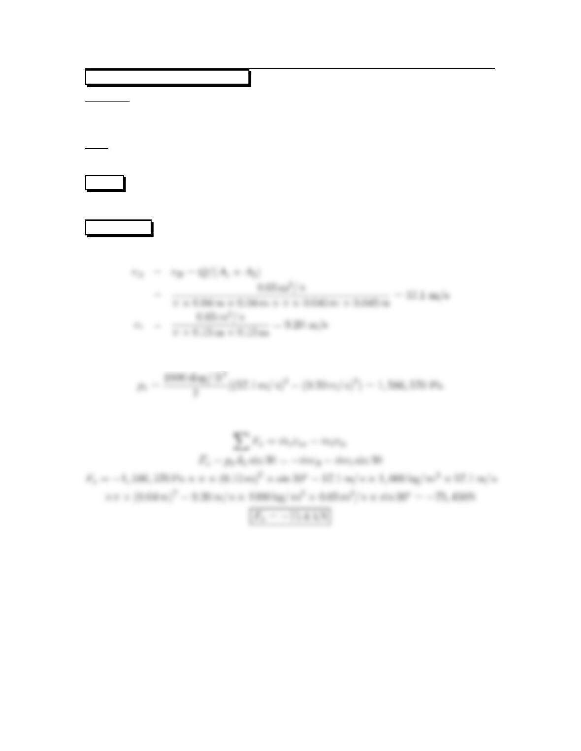
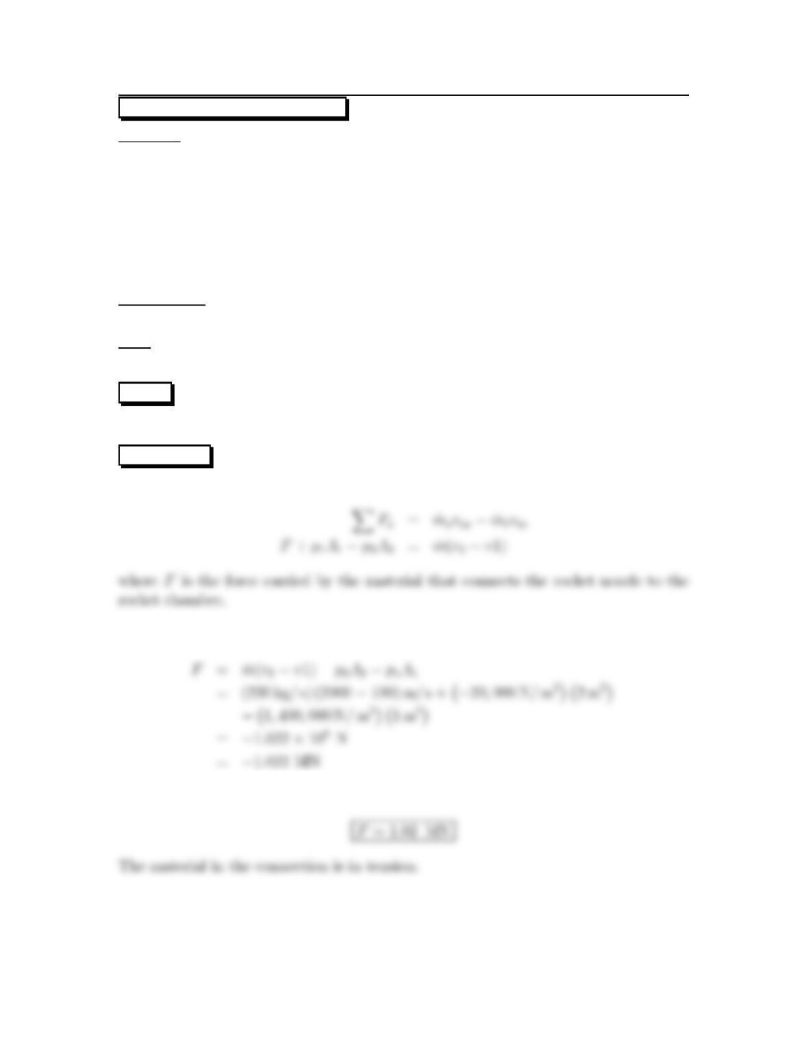
Momentum equation (x-direction)
Calculations (note the use of gage pressures).
Theforceontheconnectionwillbe
74
6.50: PROBLEM DEFINITION
Water flows through a nozzle.
Thenozzleisboltedtoapipeflange with 6 bolts.
D1=0.30 m,D
2=0.15 m,p
1= 200 kPa gage.
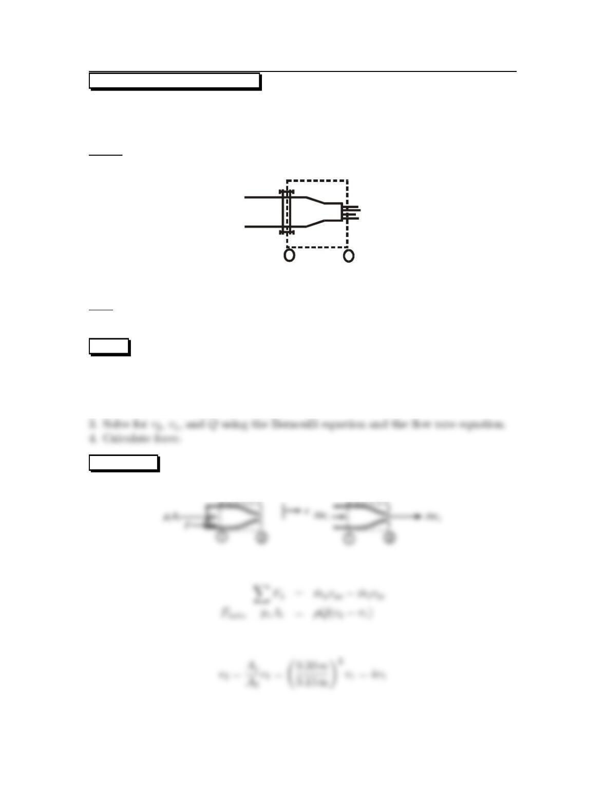
Sketch:
12
Find:
Tensionineachbolt(inNewtons)
PLAN Since force is the goal, start with the momentum equation. Then, apply
continuity and the Bernoulli equations to find terms needed to calculate force. The
steps are.
1. Apply the momentum equation to relate force to properties at 1 and 2.
2. Relate v2and v1using continuity.
SOLUTION
1. Momentum equation (x-direction)
2. Continuity equation (apply to cv shown above; accumulation is zero).
75
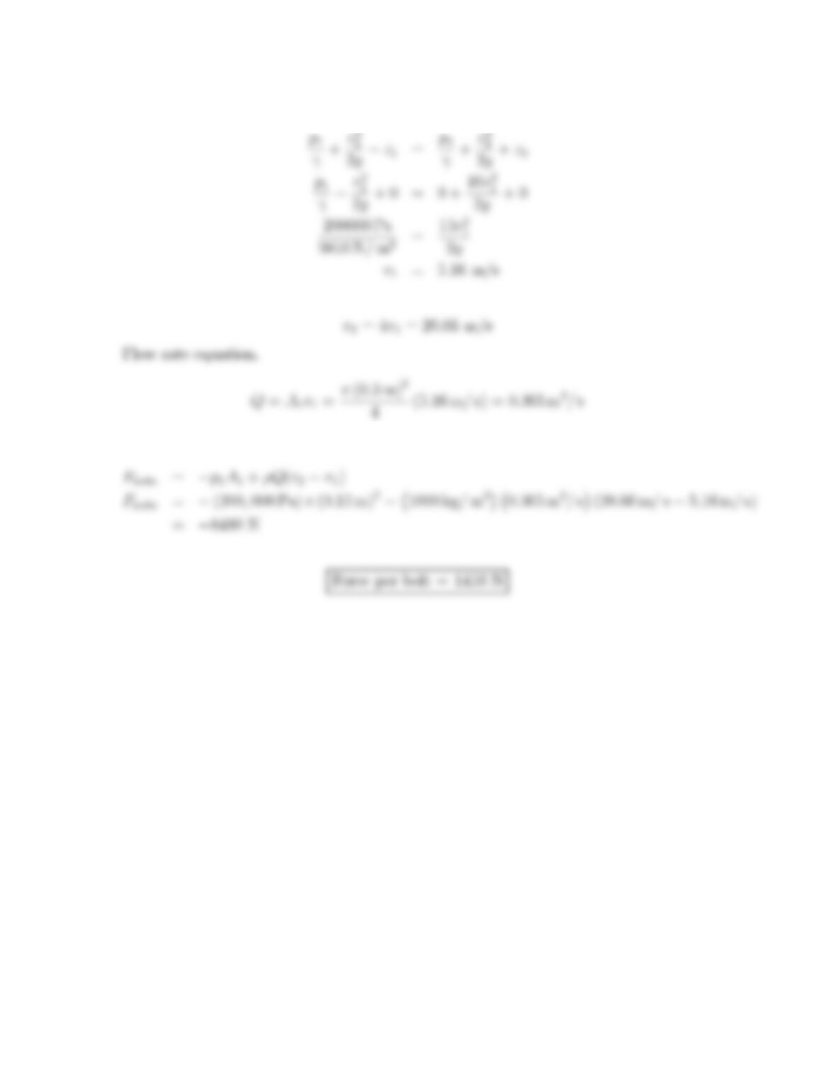
3. Bernoulli equation
4. Calculate force
76
6.51: PROBLEM DEFINITION
Situation:
Water jets out of a two dimensional slot.
Flow rate is Q=8cfs per ft of slot width. Slot spacing is H=8in.Jetheightis
b=4in.
Find:
(a)Pressure at the gage.
(b)Force (perfootoflengthofslot)of the water acting on the end plates of the
slot.
PLAN
To find pressure at the centerline of the flow, apply the Bernoulli equation. To find
the pressure at the gage (higher elevation), apply the hydrostatic equation. To find
the force required to hold the slot stationary, apply the momentum equation.
SOLUTION
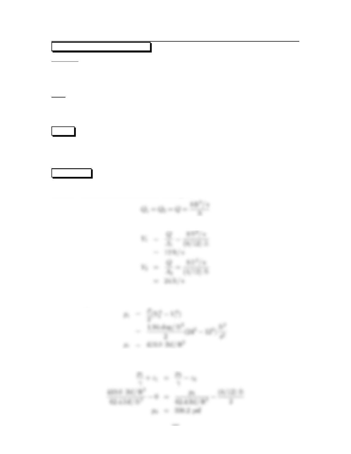
Continuity. Select a control volume surrounding the nozzle. Locate section 1 across
the slot. Locate section 2 across the water jet.
Flow rate equations
Bernoulli equation
Hydrostatic equation. Location position 1 at the centerline of the slot. Locate
position 3 at the gage.
77
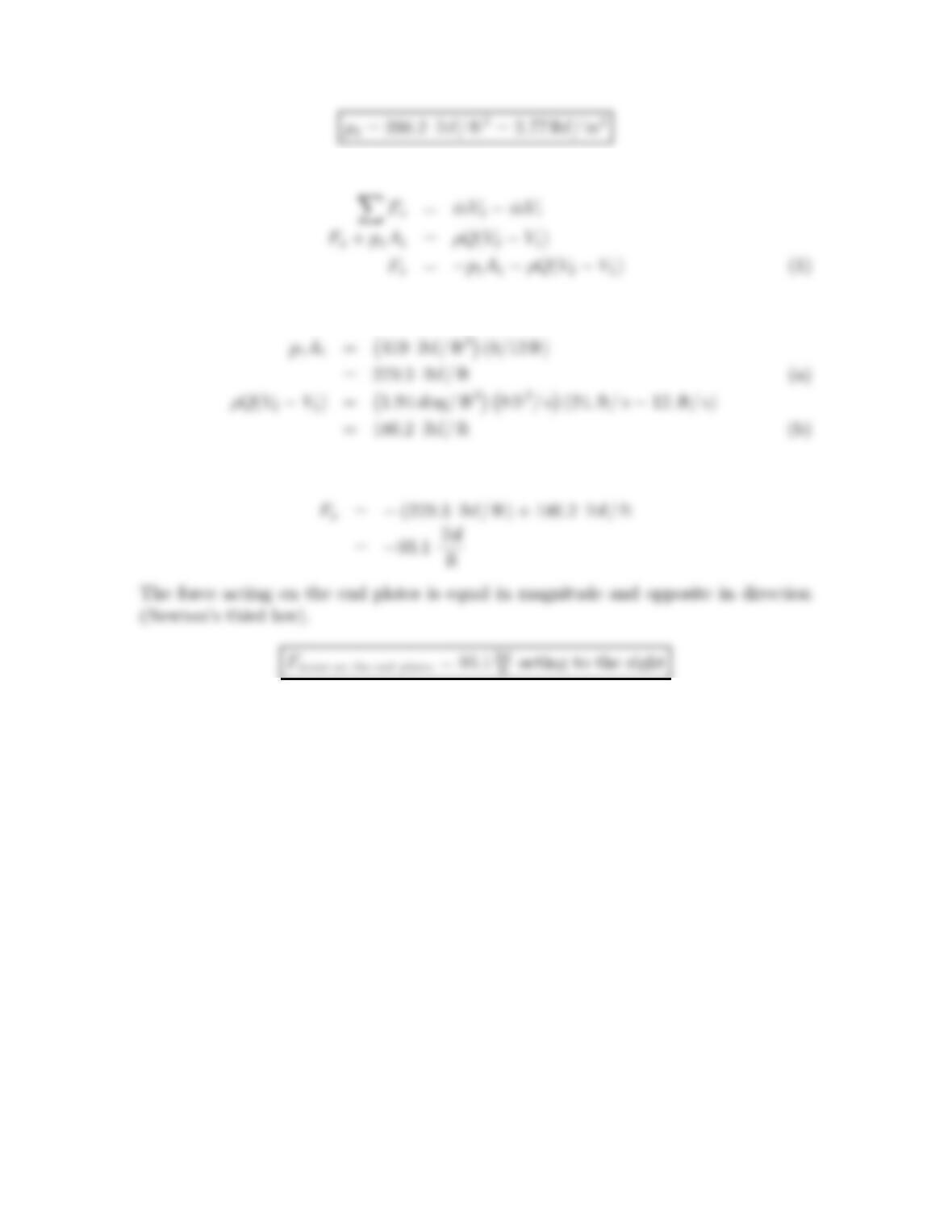
Momentum equation (x-direction)
Calculations
Substitute (a) and (b) into Eq. (1)
78
6.52: PROBLEM DEFINITION
Situation:
Water is discharged from a two-dimensional slot–additional details are provided
in the problem statement
Find:
(a)Pressure at the gage.
(b)Force (perfootoflengthofslot)on the end plates of the slot.
PLAN
Apply the Bernoulli equation, then the hydrostatic equation, and finally the momen-
tum equation.
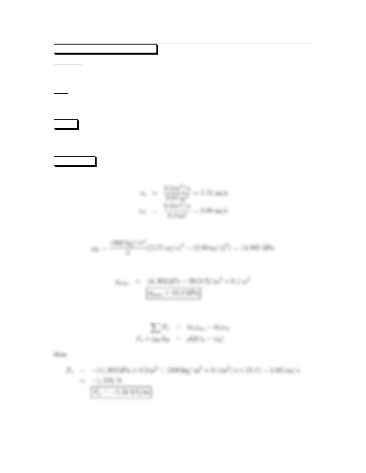
SOLUTION
Velocity calculation
Bernoulli equation
Hydrostatic equation
Momentum equation (x-direction)
79
6.53: PROBLEM DEFINITION
Situation:
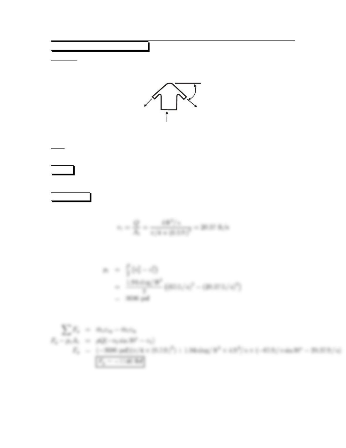
Water flows through a spray head–additional details are provided in the problem
statement.
v
1
v
2
30
o
Find:
Force acting through the bolts needed to hold the spray head on: Fy
PLAN
Apply the Bernoulli equation, and then the momentum equation.
SOLUTION
Velocity calculation
Bernoulli equation
Momentum equation (y-direction)
80