33
Problem 6.16
by the design spectrum of Fig. 6.9.5 scaled to a peak
ground motion acceleration of 0.25g.
Solution
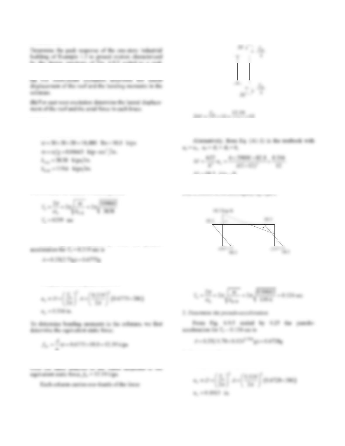
From Example 1.2:
(a) North-South excitation
1. Determine the natural vibration period.
2. Determine the pseudo-acceleration.
From Fig. 6.9.5 scaled by 0.25, the pseudo-
3. Compute peak responses.
The peak lateral displacement uo is
g
The bending moments in the columns are determined
12‘
21212
44
18.3 kip–ft
M
M
ft–kip3.18
M
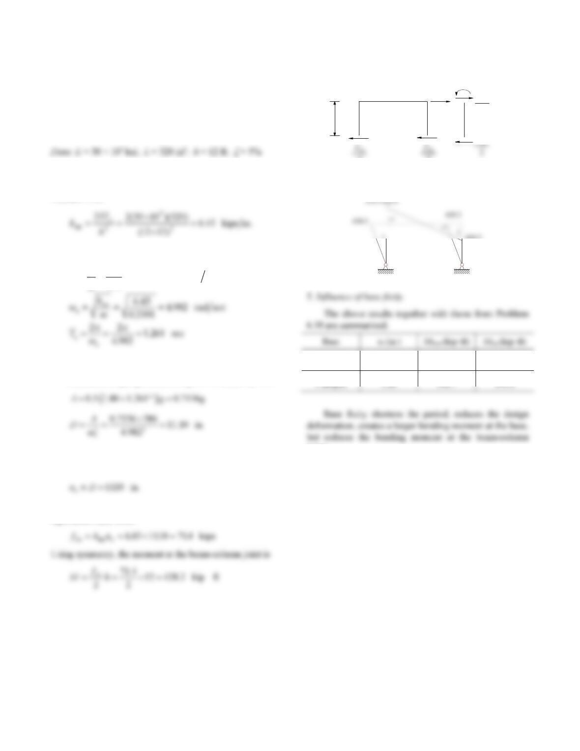
The bending moment diagram drawn on the compression
side is shown in the accompanying figure.
(
(
(
(
18.3
(b) East-West excitation
1. Determine the natural vibration period.
3. Compute peak responses.
The peak lateral displacement uo is
34
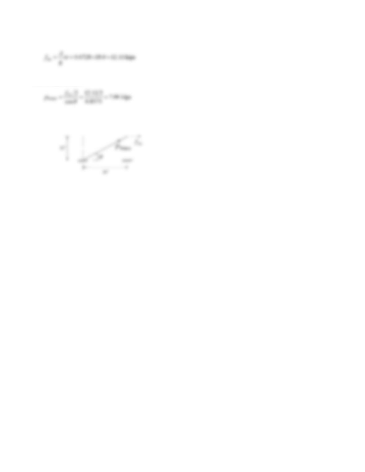
The equivalent static force is
Neglecting the lateral resistance of the columns, the axial
force in each brace is
Note that only the two braces in tension provide lateral
resistance; see Example 1.2.
35
Problem 6.17
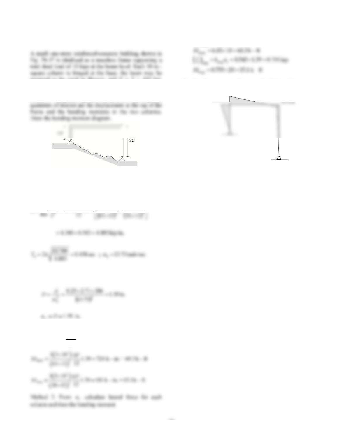
assumed to be rigid in flexure; and E = 3 × 10³ ksi.
Determine the peak response of this structure to ground
motion characterized by the design spectrum of Fig. 6.9.5
scaled to 0.25g peak ground acceleration. The response
Figure P6.17
Solution
1. Compute
T
n.
1
1
1010333
43
EI
k
2. Compute peak deformation uo.
From spectrum:
o
3. Compute bending moments.
Method 1: M3EI
L2uo
short
short
6.03 kip
4.340 1.39
so
fku
The bending moment diagrams for both columns are
shown.
Figure P6.17a
60.3 k-ft.
36
Problem 6.18
sectional area for beam and columns are Ib =160 in4 and
Ic = 320 in4, respectively; the elastic modulus for steel is
30 × 103 ksi. For purposes of dynamic analysis the frame
is considered massless with a weight of 100 kips lumped
acceleration of 0.5g.
Solution
2h
1. Determine lateral stiffness of the frame.
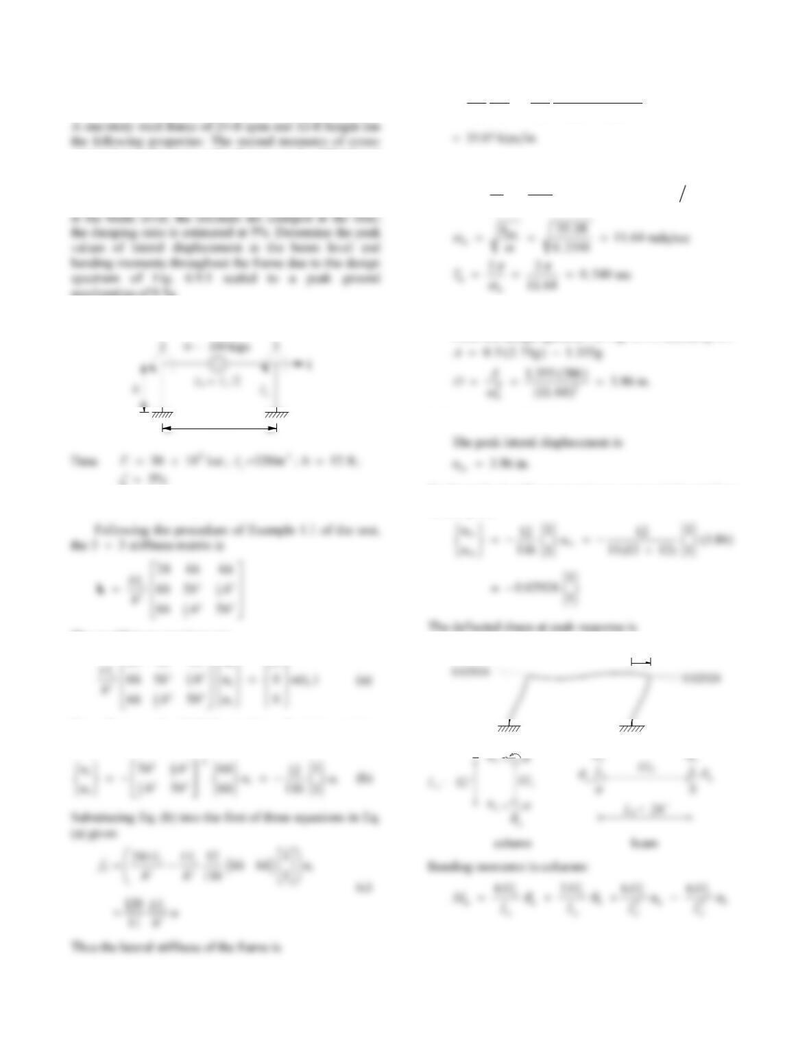
The equilibrium equations are
24 6 6
hhu f
From the second and third equations, the joint rotations
can be expressed as
3
33
120 120 (30 10 ) (320)
11 11 (12 12)
c
lat
EI
kh
2. Calculate natural period.
2
100 0.2591 kip–sec in.
g386
w
m
3. Determine spectral ordinate.
From the design spectrum of Fig. 6.9.5, scaled by 0.5
4. Determine peak responses.
To determine bending moments we recover joint rotations
from Eq. (b):
3.86 in.
b
uaub
37
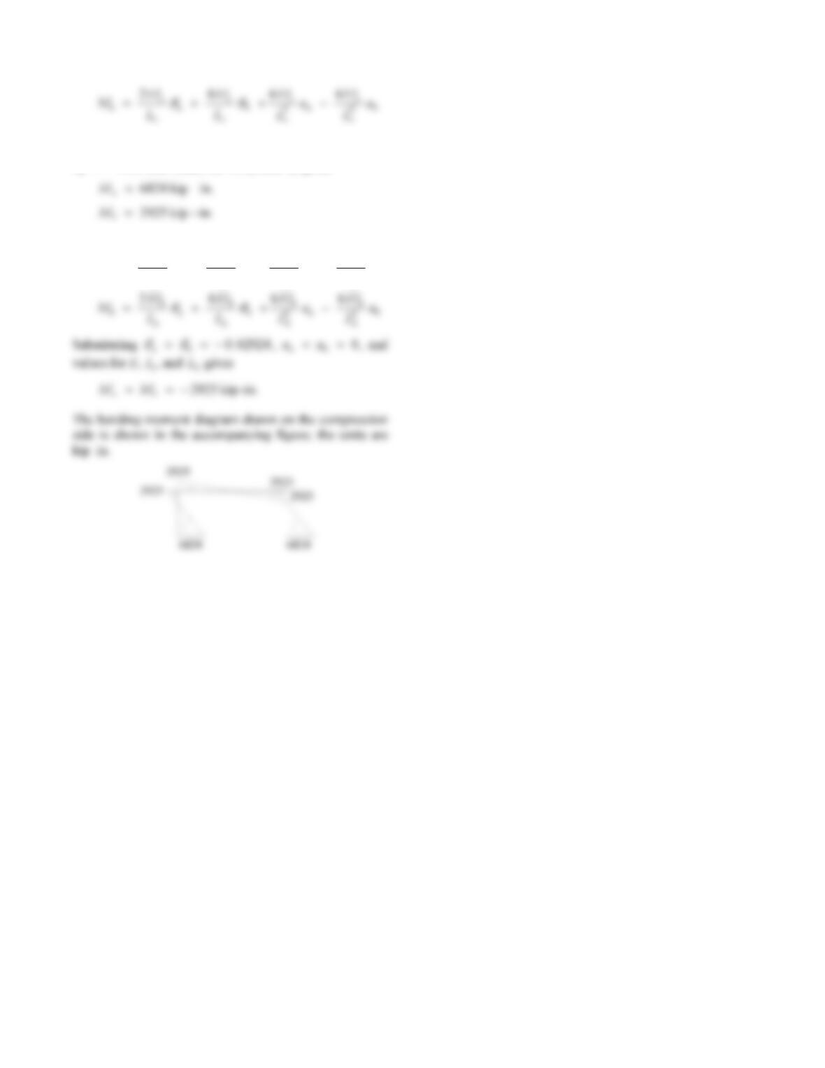
Substituting 0
a
, 0.02924
b
, 0
a
u
, and
ub386. and values for E,
I
Bending moments in beam:
MEI
L
EI
L
EI
LuEI
Lu
a
b
b
a
b
b
b
b
b
a
b
b
b
4266
22
I
38
Problem 6.19
Solve Problem 6.18 assuming that the columns are hinged
at the base. Comment on the influence of base fixity on
the design deformation and bending moments.
Solution
1. Determine lateral stiffness of the frame.
The lateral stiffness of this frame was computed in
Problem 1.16:
2. Calculate natural period.
2
100 0.2591 kip–sec in.
g386
w
m
3. Determine spectral ordinate.
From the design spectrum of Fig. 6.9.5, scaled by 0.5,
4. Determine peak responses.
The peak lateral displacement is
To determine bending moments, we first determine the
equivalent static force
12‘
fSo
fSo
M
2
2
fSo
2
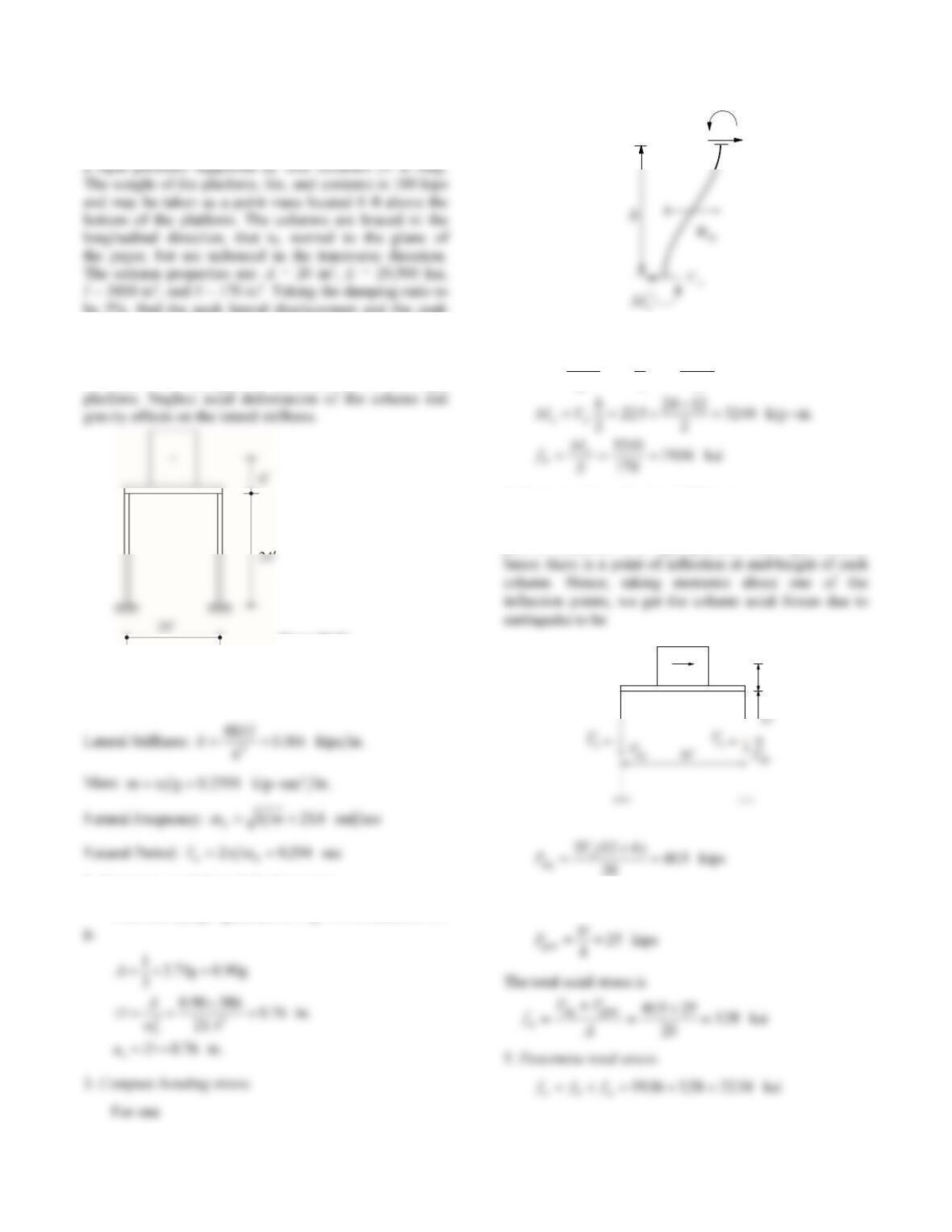
Moment diagram:
Hinged 11.1 0 428.2
Clamped 3.86 568.7 243.8
joints.
428.2
39
Problem 6.20
The ash hopper in Fig. P6.20 consists of a bin mounted on
be 5%, find the peak lateral displacement and the peak
stress in the columns due to gravity and the earthquake
characterized by the design spectrum of Fig. 6.9.5 scaled
to 1/3 g acting in the transverse direction. Take the
columns to be clamped at the base and at the rigid
Figure P6.20
Solution
1. Determine structural properties.
2. Determine peak lateral displacement.
From the design spectrum of Fig. 6.9.5, scaled to 1/3
Column:
VEI
huku
ooo
12
4
118 6
4076 225
3
...
kips
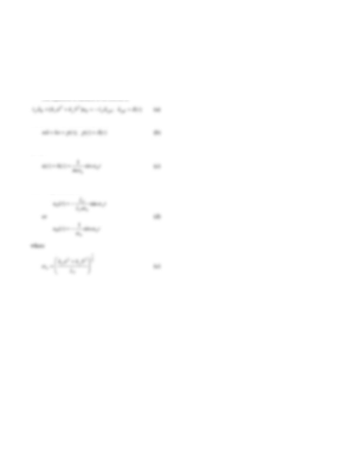
4. Compute stress due to axial forces.
The sketch represents half of the structure, i.e., one
pair of columns with rigid platform and rigid column
2Vo
6‘
The axial force in each column due to gravity load is
Vo
Mo
40
Problem 6.21
The structure of Example 1.7 subjected to rotational
acceleration ݑሷ gθ = δ(t) of the foundation. Derive an
equation for the rotation uθ(t) of the roof slab in terms of
IO, kx, ky, b, and d. Neglect damping.
Solution
The equation of motion to be solved is
We have solved a related equation:
and its solution is given by Eq. (4.1.7) specialized for
= 0:
Therefore, solution to Eq. (a) is Eq. (c) multiplied by –IO
with m replaced by IO:
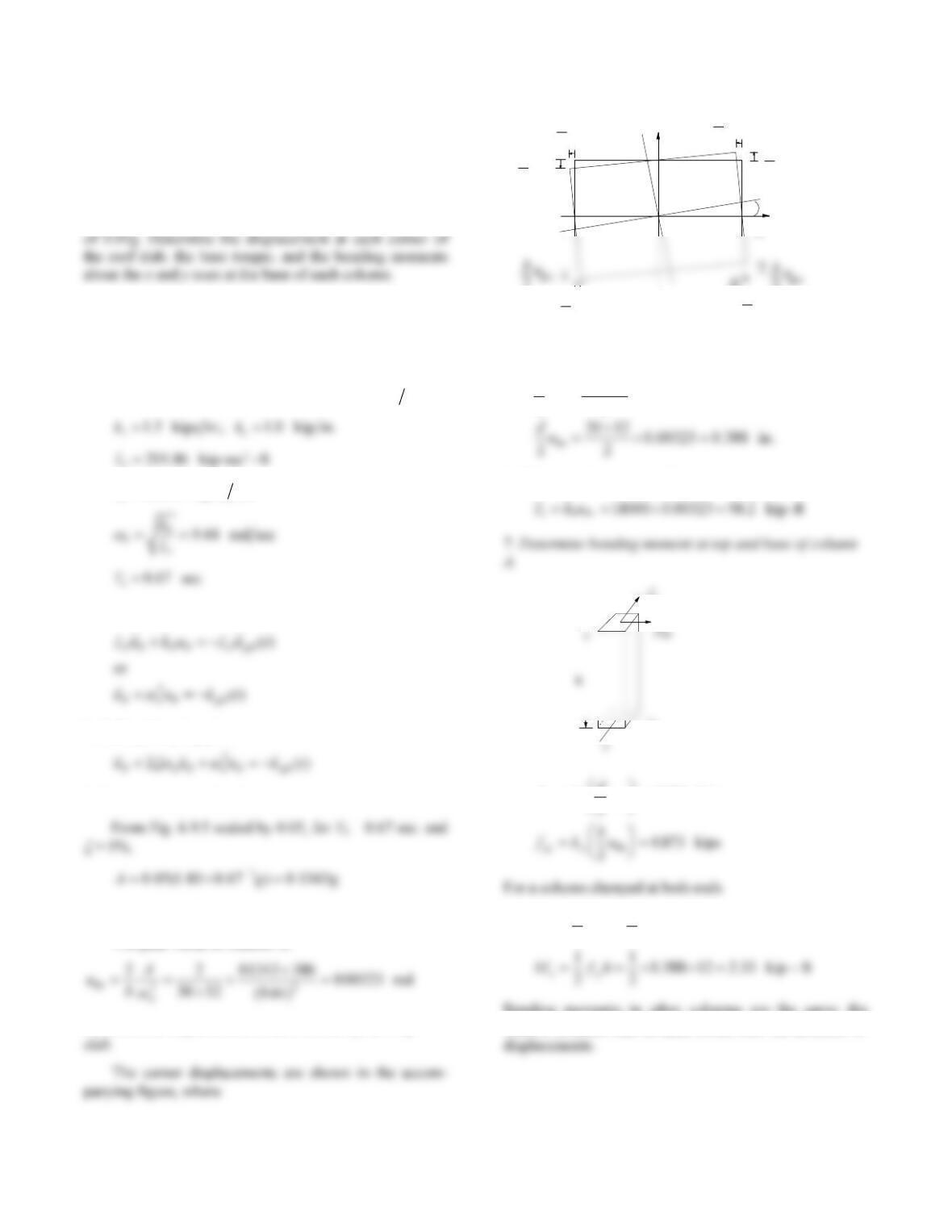
41
Problem 6.22
The peak response of the system described in Examples
1.7 and 2.4 due to rotational ground acceleration ݑሷ gθ (see
Fig. E1.7) is to be determined; ζ = 5%. The design
spectrum for translational ground acceleration (b/2)ݑሷ gθ is
given by Fig. 6.9.5 scaled to a peak ground acceleration
Solution
1. Define structural properties.
From Example 2.4:
2
30 ft; 20 ft; 12 ft; 0.1 kip ft
18000 kip-ft rad
w
bd h
k
2. Write equation of motion.
Including damping gives
3. Determine spectral ordinate.
4. Determine peak rotation.
The peak value of rotation is
5. Determine displacement at each corner of the roof
A
x
y
2uo
2uo
b
2uo
b
2uo
2uo
d
2uo
d
2uo
d
2uo
d
uo
in.582.000323.0
2
1230
2
o
u
b
6. Determine base torque To.
x
fsy
fk
du
sx x o
.
kips
ft–kip24.512873.0
2
1
2
1
hfM
sxy
Bending moments in other columns are the same; the
relative direction can be determined from the direction of
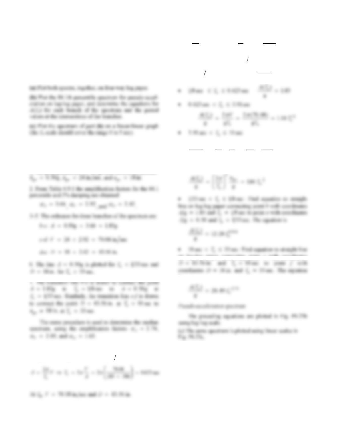
42
Problem 6.23
For the design earthquake at a site, the peak values of
ground acceleration, velocity, and displacement have been
estimated: ݑሷ go = 0.5g, ݑሷ go = 24 in./sec, and ugo = 18 in. For
systems with 2% damping ratio, construct the 50th and
84.1th percentile design spectra.
Solution
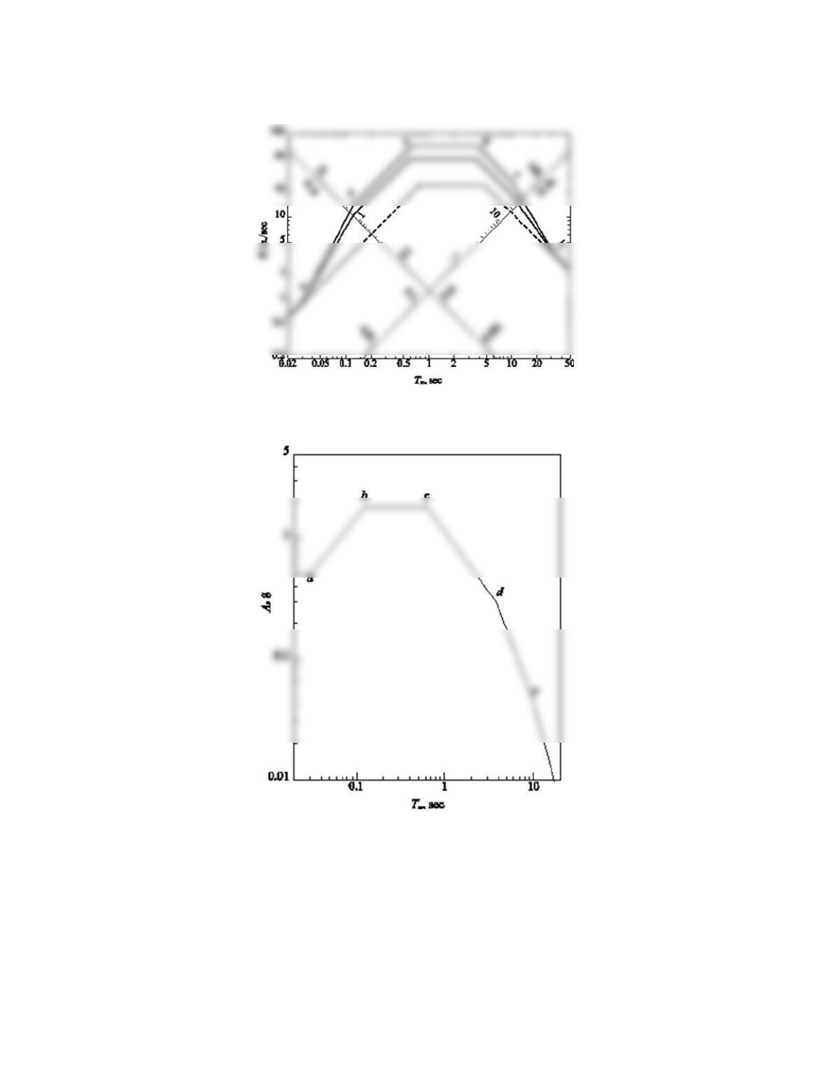
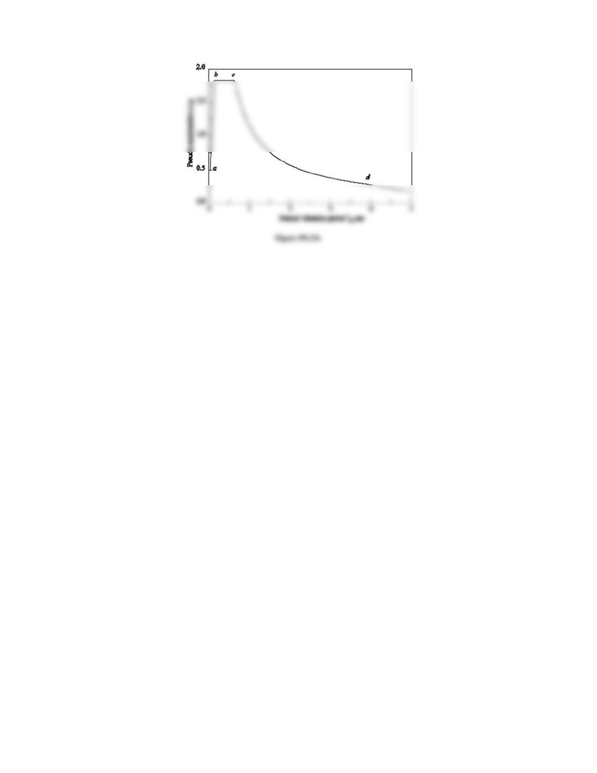
(a) With reference to Fig. P6.23a, the design spectrum is
determined by the following steps:
1. The peak parameters for the ground motion are plotted:
F
A
A
A
T
A
A
A
A
T
(b) Determine T
c and T
d.
At T
c,
A
183.g and V70 08. secin.
VTDT D
V
n
n
F
H
GI
K
J
222
4356
70 08 391
.
..sec
Determine equations for
A
Tn
()g.
Tn
1 33 sec
A
T
n
() .
g05
AT
T
D
TT
n
nn
n
() ..
ggg
F
H
GI
K
J
F
H
GI
K
J
224356
446
22
2
Tn33 sec
on log–log paper connecting point e with coordinates
is
A
T
A
43
Figure P6.23a
Figure P6.23b
44