6.1: PROBLEM DEFINITION
Situation:
Identify the surface and body forces acting on a glider in flight. Also, sketch a free
body diagram and explain how Newton’s laws of motion apply.
Find:
Surface and body forces acting on a glider in flight.
PLAN
Make use of a sketch with a free-body diagram.
SOLUTION
The forces acting on glider in flight are:
Surface forces:
1. Lift – a surface force because the wing must touch the air to generate lift.
1
6.2: PROBLEM DEFINITION
Situation:
Interpretation of Newton’s second law.
F=d(mv)
dt ,F=mdv
dt +vdm
dt
Find:
Relationship between momentum and acceleration.
SOLUTION
Expressing Newton’s second law as
2
6.3: PROBLEM DEFINITION
Situation:
Which are the following are correct with respect to the derivation of the Momentum
Equation? (Select all that apply.)
a. Reynold’s Transport Theorem is applied to Fick’s Law.
b. The extensive property is momentum.
c. The intensive property is mass.
d. The velocity is assumed to be uniformly distributed across each inlet and outlet.
e. The net momentum flow is the “ins” minus the “outs”.
f.ThenetforceisthesumofforcesactingonthematterinsidetheCV
SOLUTION
3
6.4: PROBLEM DEFINITION
Situation:
When making a force diagram (FD) and its partner momentum diagram (MD) in
order to set up the equations for a momentum equation problem (see Fig. 6.10 in
§6.3), which of the following elements should be in the FD, and which should be in
the MD?
(Classify all below as either FD or MD.)
a. Each mass stream with product ˙movoor product ˙mivicrossing a control surface
boundary.
b. Reaction forces required to hold walls, vanes, or pipes in place.
c. Weight of a solid body that contains or contacts the fluid.
d. Weight of the fluid.
e. Pressure force caused by a fluid flowing across a control surface boundary.
SOLUTION
a. All products of the form ˙mv should be in the MD
4
6.5: PROBLEM DEFINITION
Situation:
Examples of jets and how used in practice.
Find:
Give 5 examples of jets and applications.
SOLUTION
1. Water jet from a fire hose – fire suppression
5
6.6: PROBLEM DEFINITION
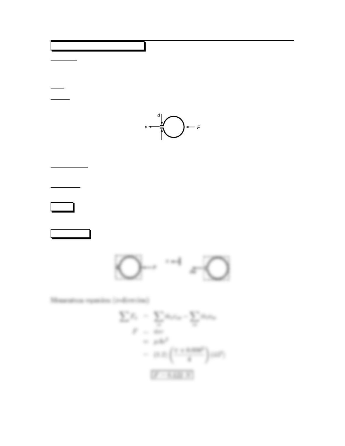
Situation:
A balloon is held stationary by a force F.
d=8mm,v=45m/s.
Find: Force required to hold balloon stationary (N).
Sketch:
Assumptions:
Steady flow, constant density.
Properties:
ρ=1.2kg/m3.
PLAN
Apply the momentum equation.
SOLUTION
Force and momentum diagrams (x-direction terms)
6
6.7: PROBLEM DEFINITION
Situation:
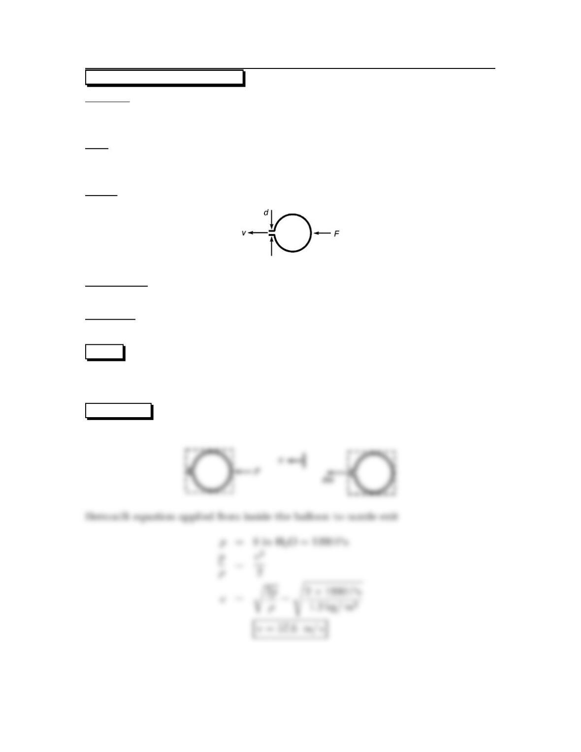
A balloon is held stationary by a force.
d=1cm,p=8in H2O.
Find:
x-component of force required to hold balloon stationary (N).
Exit velocity (m/s).
Sketch:
Assumptions:
Steady, irrotational, constant density flow.
Properties:
ρ=1.2kg/m3.
PLAN
To find the exit velocity, apply the Bernoulli equation. To find the force, apply the
momentum equation.
SOLUTION
Force and momentum diagrams (x-direction terms)
7
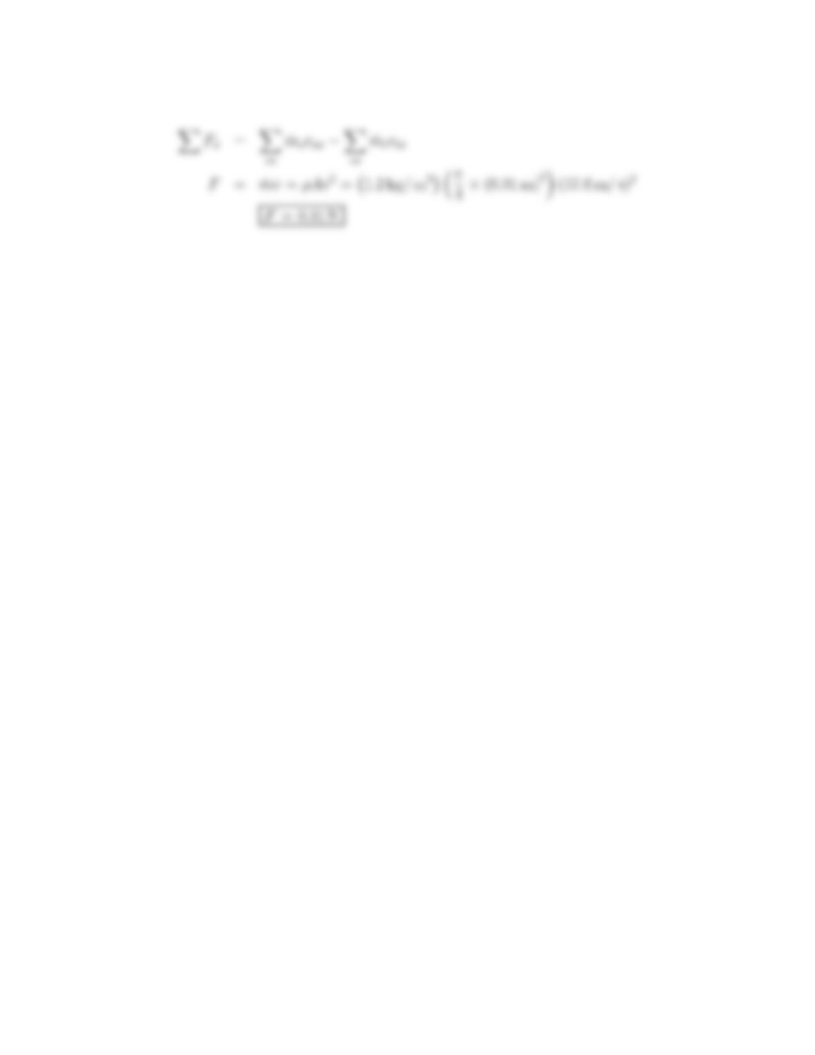
Momentum equation (x-direction)
8
6.8: PROBLEM DEFINITION
Situation:
For Example 6.2 in §6.4, the situation diagram shows concrete being “shot” at
an angle into a cart that is tethered by a cable, and sitting on a scale. Determine
whether the following two statements are “true” or “false.”
a. Mass is being accumulated in the cart.
b. Momentum is being accumulated in the cart.
SOLUTION
9
6.9: PROBLEM DEFINITION
Situation:
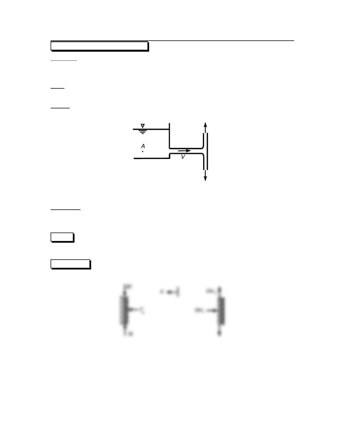
Awaterjetisfilling a tank.
m=25kg,V=25L.
d=30mm,v=25m/s.
Find:
Forceonthebottomofthetank(N).
Force acting on the stop block (N).
Assumptions:
Steady flow.
Properties:
Water (15 ◦C), Table A.5: ρ=999kg/m3,γ=9800N/m3.
PLAN
Apply the momentum equation in the x-direction and in the y-direction.
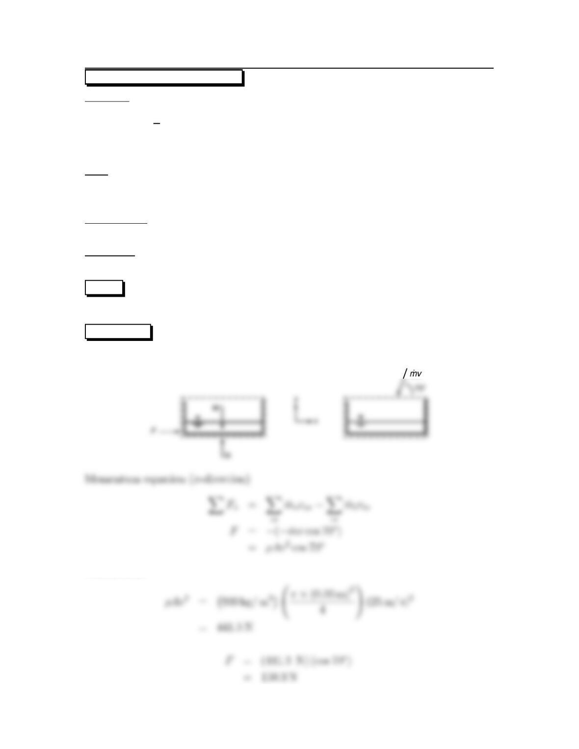
SOLUTION
Force and momentum diagrams
Calculations
10
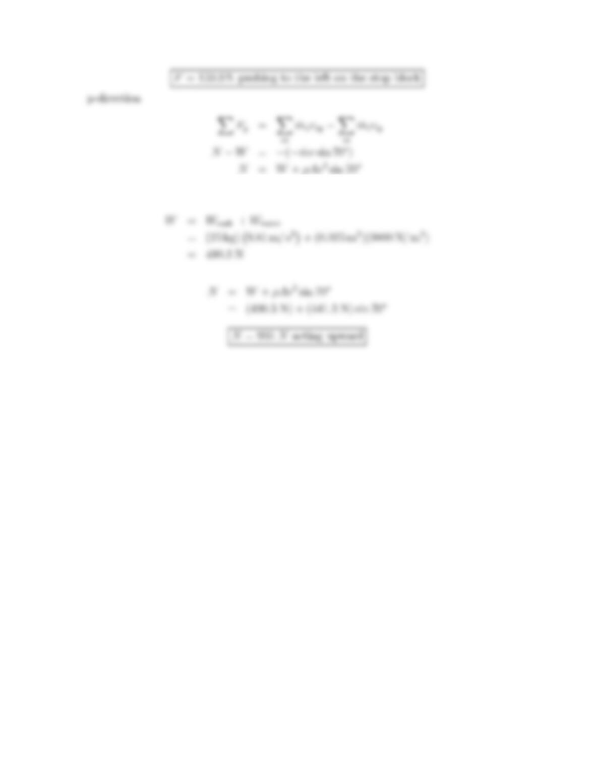
Calculations:
11
6.10: PROBLEM DEFINITION
Situation:
Water jet is filling a tank.
m=25lbm, V= 6 gal.
d=2in.,v=60ft/s.
Find:
Minimum coefficient of friction so force on stop block is zero.
Assumptions:
Steady flow, constant density, steady and irrotational flow.
Properties:
Water (70 ◦F), Table A.5: ρ=1.94 slug/ft3,γ=62.4lbf/ft3.
PLAN
Apply the momentum equation in the x– and y-directions.
SOLUTION
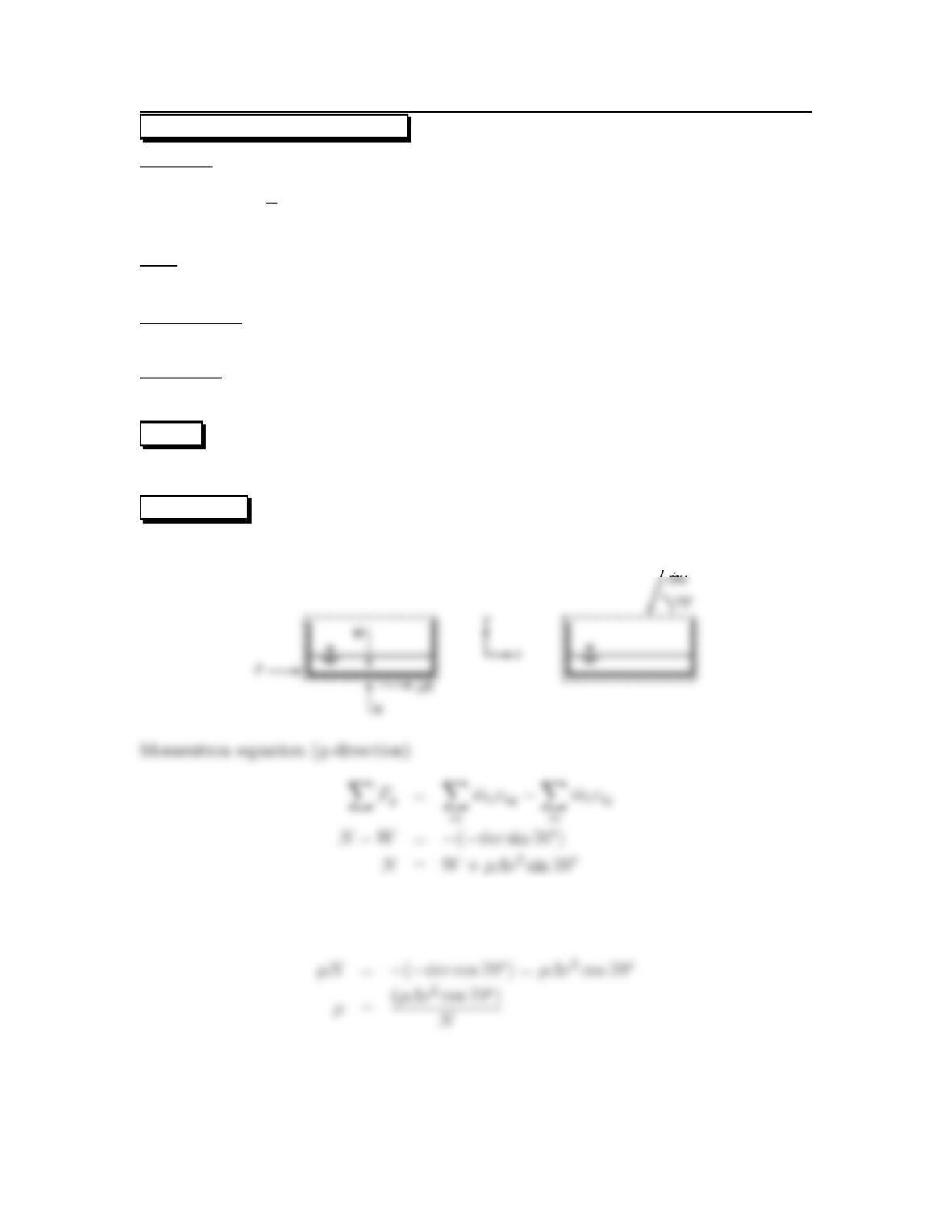
Force and momentum diagrams
Momentum equation (x-direction)
12
Calculations
13
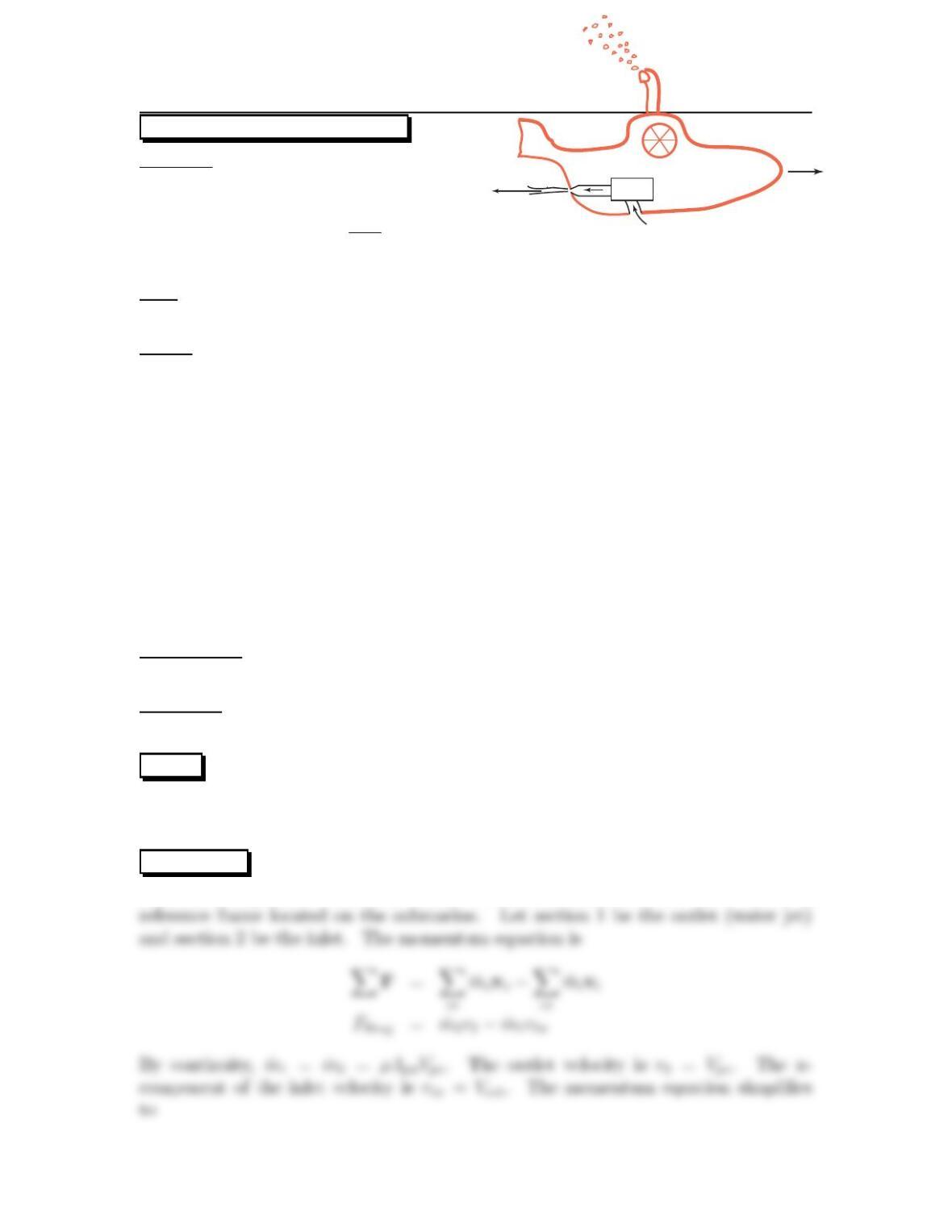
6.11: PROBLEM DEFINITION
Situation:
A design contest features a submarine powered by a water jet.
Vsub =1.0m/s,D1=25mm.
D2=5mm,FD=CD³ρV 2
sub
2´Ap
CD=0.3,Ap=0.28 m2.
Find:
Speed of the fluid jet (m/s).
Sketch:
Vsub
Vjet
Pump
Assumptions:
Assume steady flow so that the accumulation of momentum term is zero.
Properties:
Water (15 ◦C), Table A.5: ρ=999kg/m3.
PLAN
The speed of the fluid jet can be found from the momentum equation because the
drag force will balance with the net rate of momentum outflow.
SOLUTION
Momentum equation. Select a control volume that surrounds the sub. Select a
14
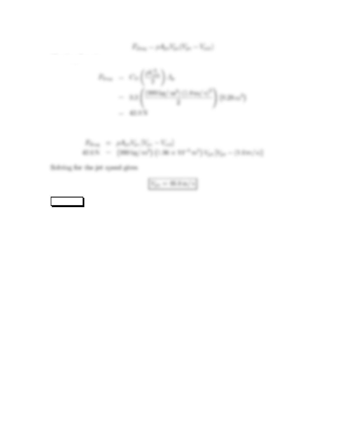
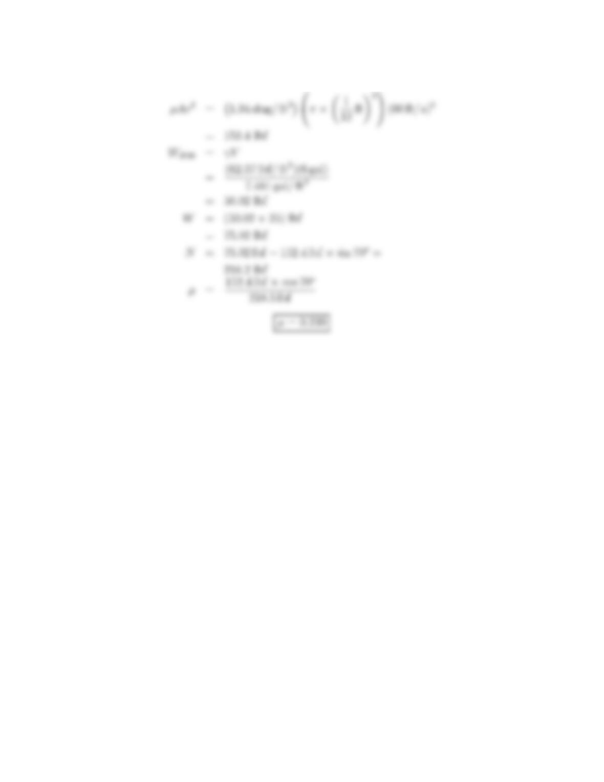
The drag force is
The momentum equation becomes
REVIEW
1. The jet speed (46.6 m/s) is above 100 mph. This present a safety issue. Also,
this would require a pump that can produce a large pressure rise.
2. It is recommended that the design be modified to produce a lower jet velocity.
Onewaytoaccomplishthisgoalistoincreasethediameterofthejet.
15
6.12: PROBLEM DEFINITION
Situation:
Horizontal round jet strikes a plate.
Q=2cfs,F
x=200lbf.
Find:
Speed of water jet (ft/s).
Sketch:
Properties:
Water (70oF),Table A.5: ρ=1.94 slug/ft3.
PLAN
Apply the momentum equation to a control volume surrounding the plate.
SOLUTION
Force and momentum diagrams
Momentum equation (x-direction)
16
6.13: PROBLEM DEFINITION
Situation:
Horizontal round jet strikes a plate.
Fx=600lbf
Find:
Diameter of jet (ft).
Sketch:
Properties:
pA=25psig.
Water (70 oF),Table A.5: ρ=1.94 slug/ft3.
PLAN
Apply the Bernoulli equation, then the momentum equation.
SOLUTION
Force and momentum diagrams
17
Bernoulli equation applied from inside of tank to nozzle exit
Momentum equation (x-direction)
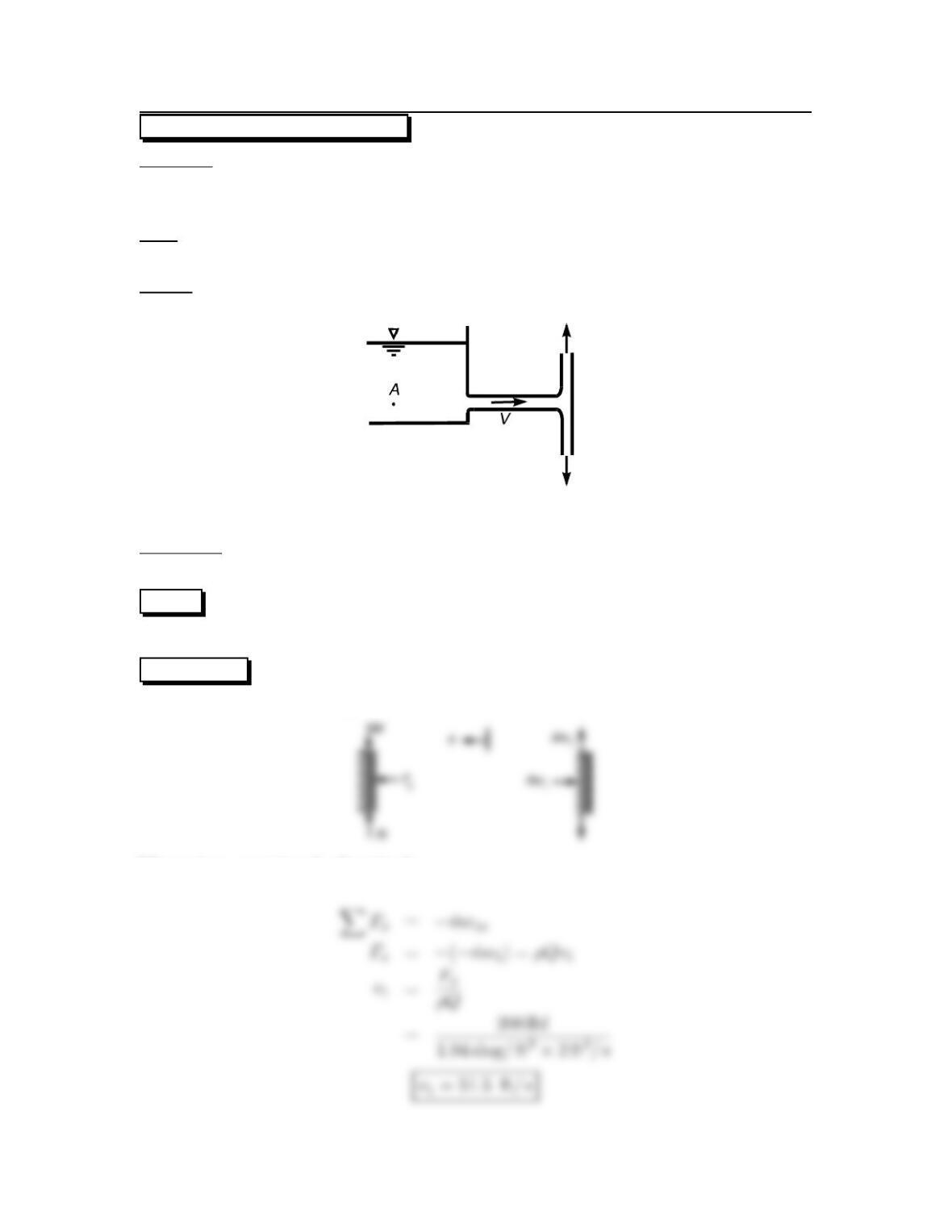
6.14: PROBLEM DEFINITION
Situation:
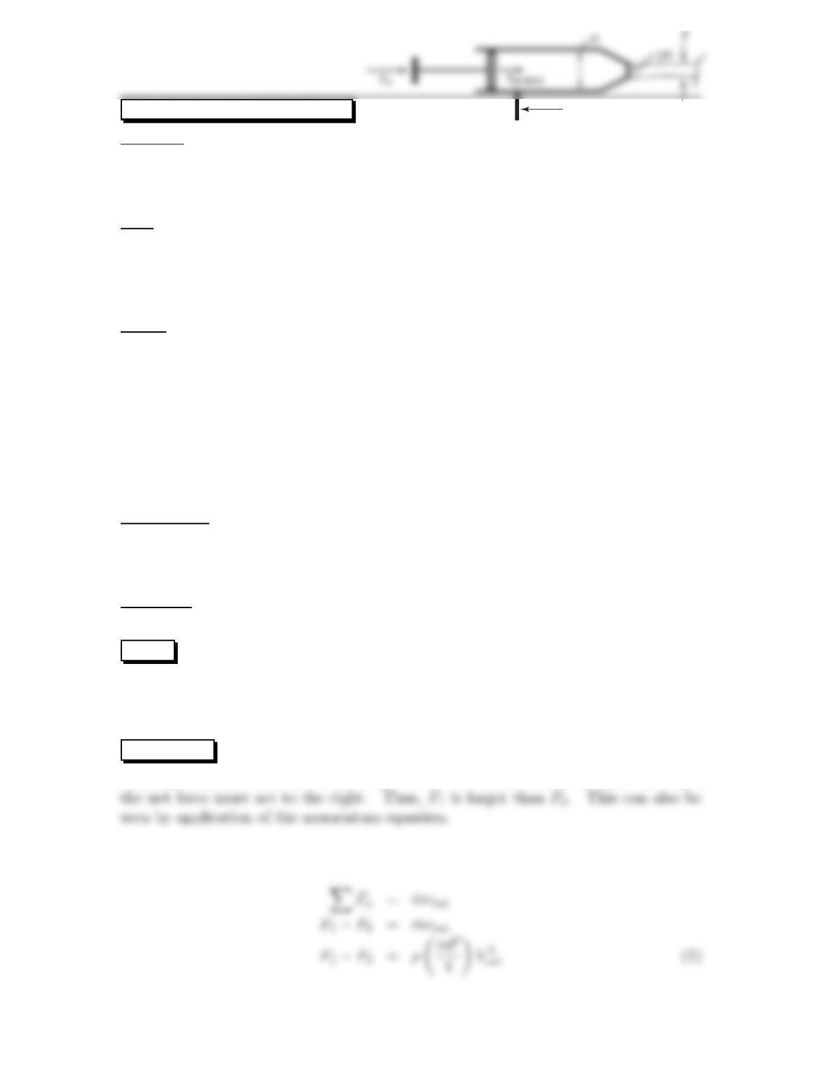
An engineer is designing a toy to create a jet of water.
D=80mm,d=15mm.
Vpiston =300mm/s.
Find:
Which force (F1versus F2)is larger? Explain your answer using concepts of the
momentum equation.
Calculate F1.
Calculate F2.
Sketch:
F2
Assumptions:
Neglect friction between the piston and the wall.
Assume the Bernoulli equation applies (neglect viscous effects; neglect unsteady
flow effects).
Properties:
Table A.5 (water at 20 ◦C): ρ=998kg/m3.
PLAN
To find the larger force, recognize that the net force must be in the direction of accel-
eration. To solve the problem, apply the momentum equation, continuity equation,
equilibrium equation, and the Bernoulli equation.
SOLUTION
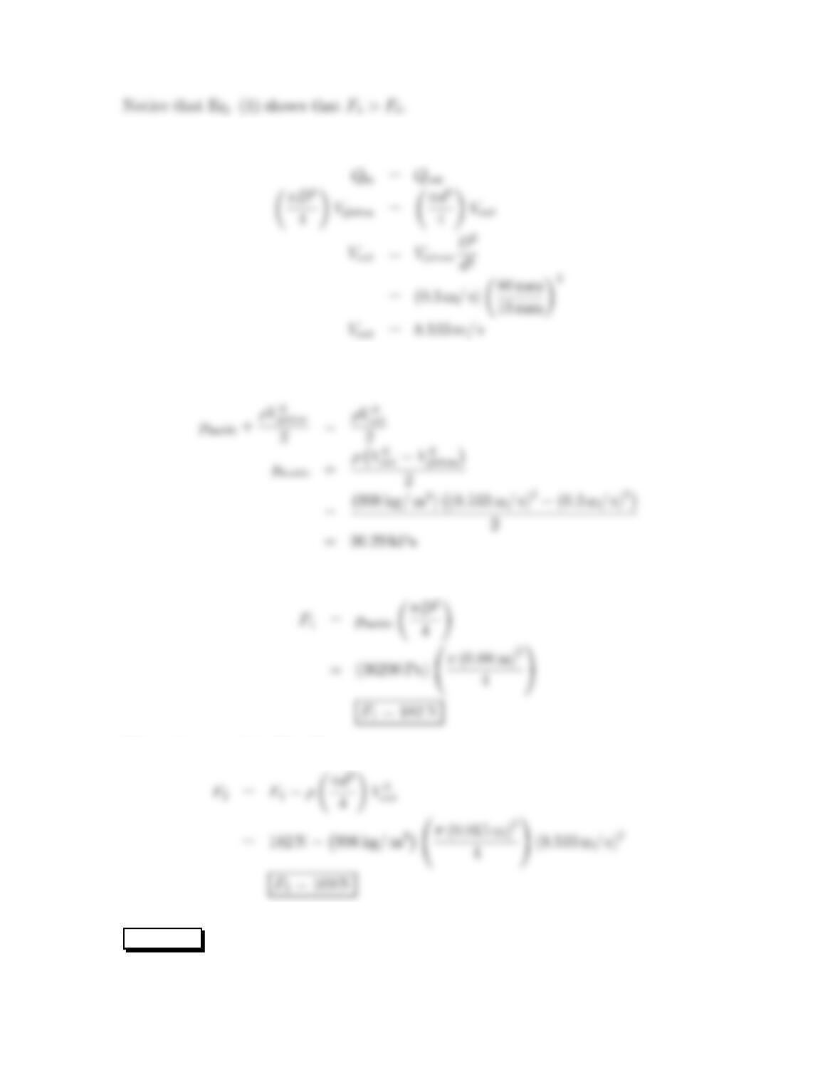
Finding the larger force (F1versus F2).Since the fluid is accelerating to the right
Momentum equation (x-direction) applied to a control volume surrounding the toy.
19
Continuity equation applied to a control volume situated inside the toy.
Bernoulli equation applied from inside the toy to the nozzle exit plane.
Equilibrium applied to the piston (the applied force F1balances the pressure force).
Momentum equation (Eq. 1)
REVIEW
1. The force F1is only slightly larger than F2.
20