(c) For
θ
=60, we use Eq. (4) to get
22
3
2
2
2
3
kg l mm N
999 5 (0.5 m)(cos 60 ) 1000 1 m
sm
mkg s
l
1000 (3)( mm )
m
shaft
T
⋅
=
18
Problem 5.84
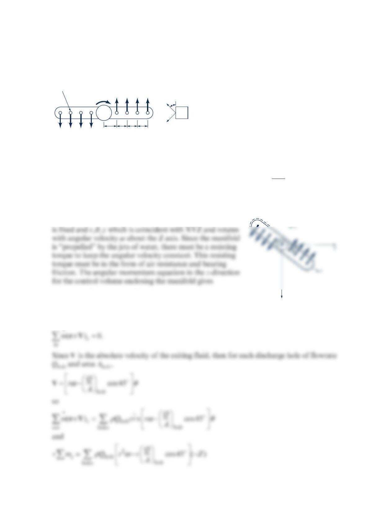
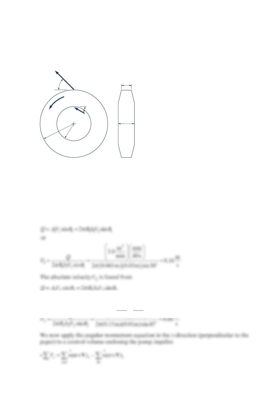
The figure below shows a simplified sketch of a dish-washer water supply manifold. Find
the resisting torque for a water temperature of 140 F
. =0.25gal/minQ and
ω
=3rpm.
Solution 5.84
GIVEN: Dishwasher supply manifold with volume flowrate =gal
0.25 min
Q. Steady state.
ω
=3rpm. 140 F
.
FIND: Resisting torque.
SOLUTION: We set up two coordinate systems: XYZ which
() ()
zzz
out in
Tm m
+
=×−×
rV rV
Assuming the water enters the manifold vertically and at 0,r=
3 in. 2 in.2 in.
¼-in.-diameter holes
2 in.
45
°
Q
ω
Q Q Q
Q Q Q Q
y
Assuming the flowrate is equally divided among the holes,
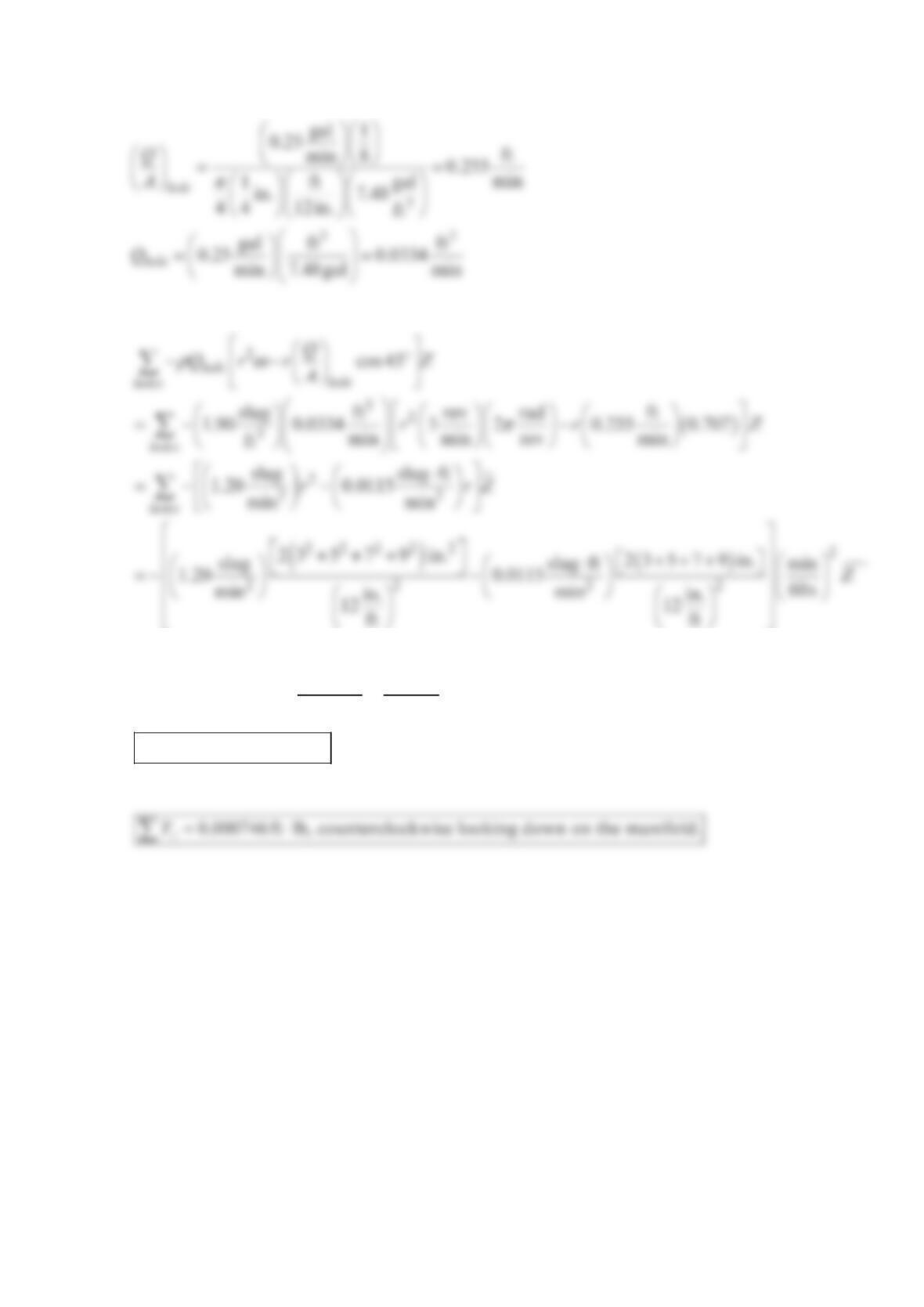
Then for 140 F
water,
or
⋅⋅
+=−
⋅
+=− ⋅
22
2
slug ft lb s
0.000746 slug ft
s
0.000746 ft lb
z
z
T
T
or
Problem 5.85
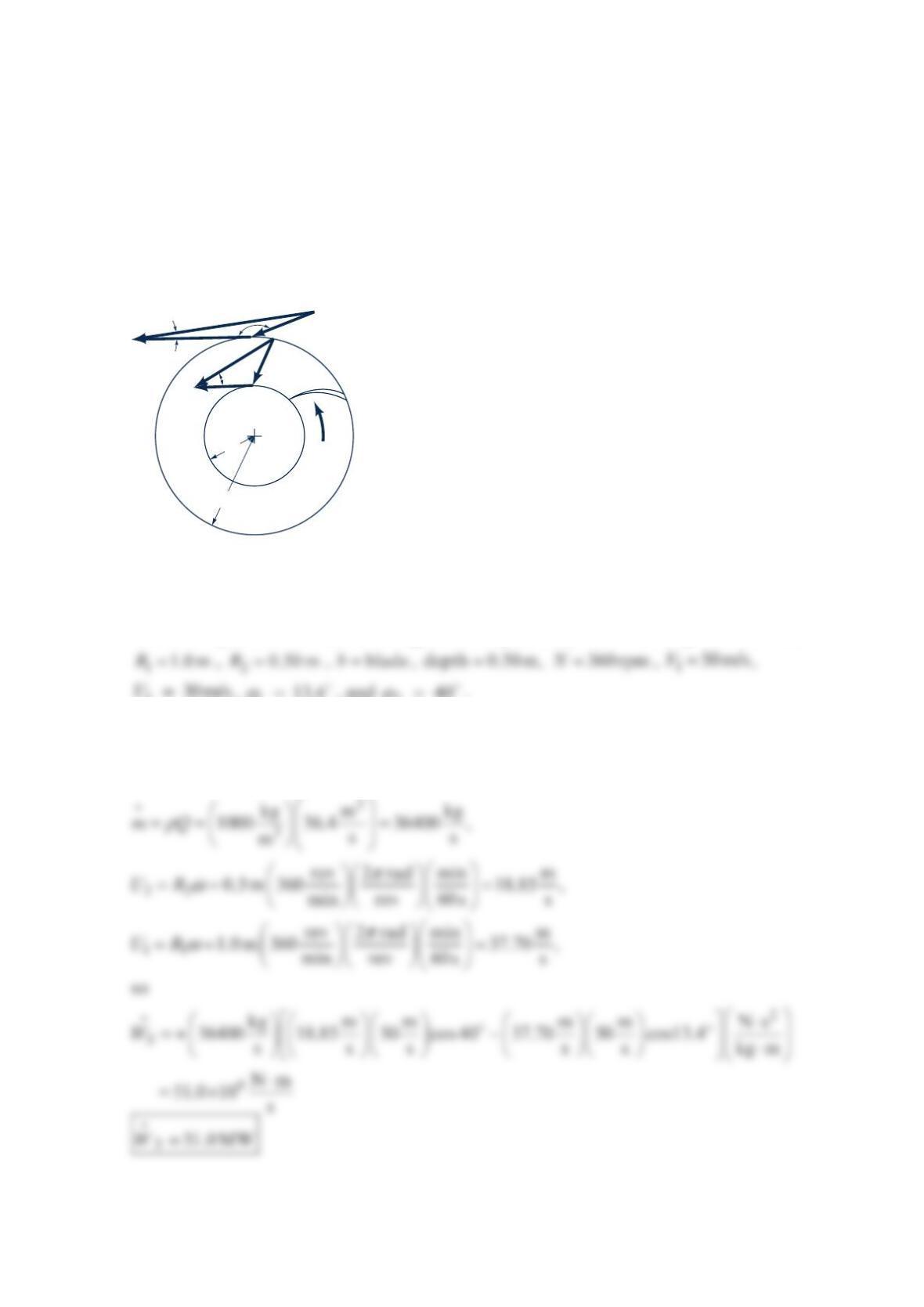
The hydraulic turbine shown in the figure below has a 10 C
water flowrate of 3
36.4 m /s ,
an inlet radius =
1 1.0 mR, an outlet radius =
2 0.50 mR, a blade depth (perpendicular to
paper) = 0.50 mh, and a rotational speed =360 rpmN; =
1 50 m/sV, =
2 30 m/sV,
α
=
1 13.4, and
α
=
2 40. Calculate the power transferred by the fluid to the rotor, the
inlet relative velocity 1
W
, and the direction 1
W
makes with the radius at the inlet.
Solution 5.85
GIVEN: Hydraulic turbine in the figure in the problem,
1
0 C° water, =3
36.4 m / sQ,
=
2 30 m/sV,
α
=
1 13.4, and
α
=
2 40.
FIND: Power transferred by water to turbine and the magnitude and direction of 1
W
.
SOLUTION: The power is
()
αα
=+ −
22 2 11 1
cos cos
S
WmUV UV
Blade
ω
α
R
1
R
2
W
1
W
2
U
2
U
1
V
1
1
α
2
β
1
V
2
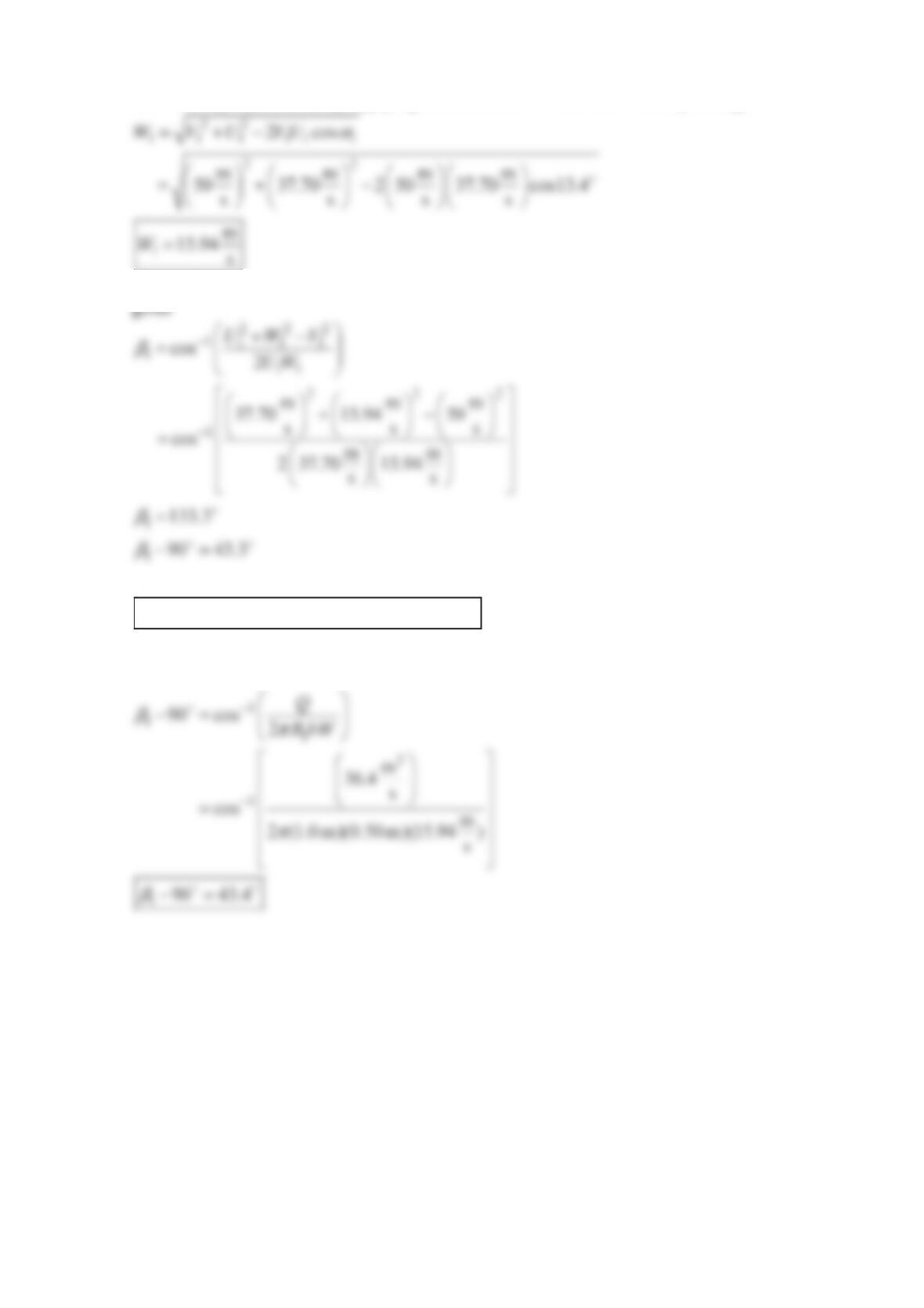
The velocity 1
W
is found by applying the cosine law to the inlet velocity triangle.
The angle that 1
W
makes with the radius can be found by finding 1.
β
The law of cosines
1
so
makes an angle of 43.3 with the radius.
W
A second way to find this angle is to use
πβ
=−
11 1
2cos(90)
QRbW
Problem 5.86
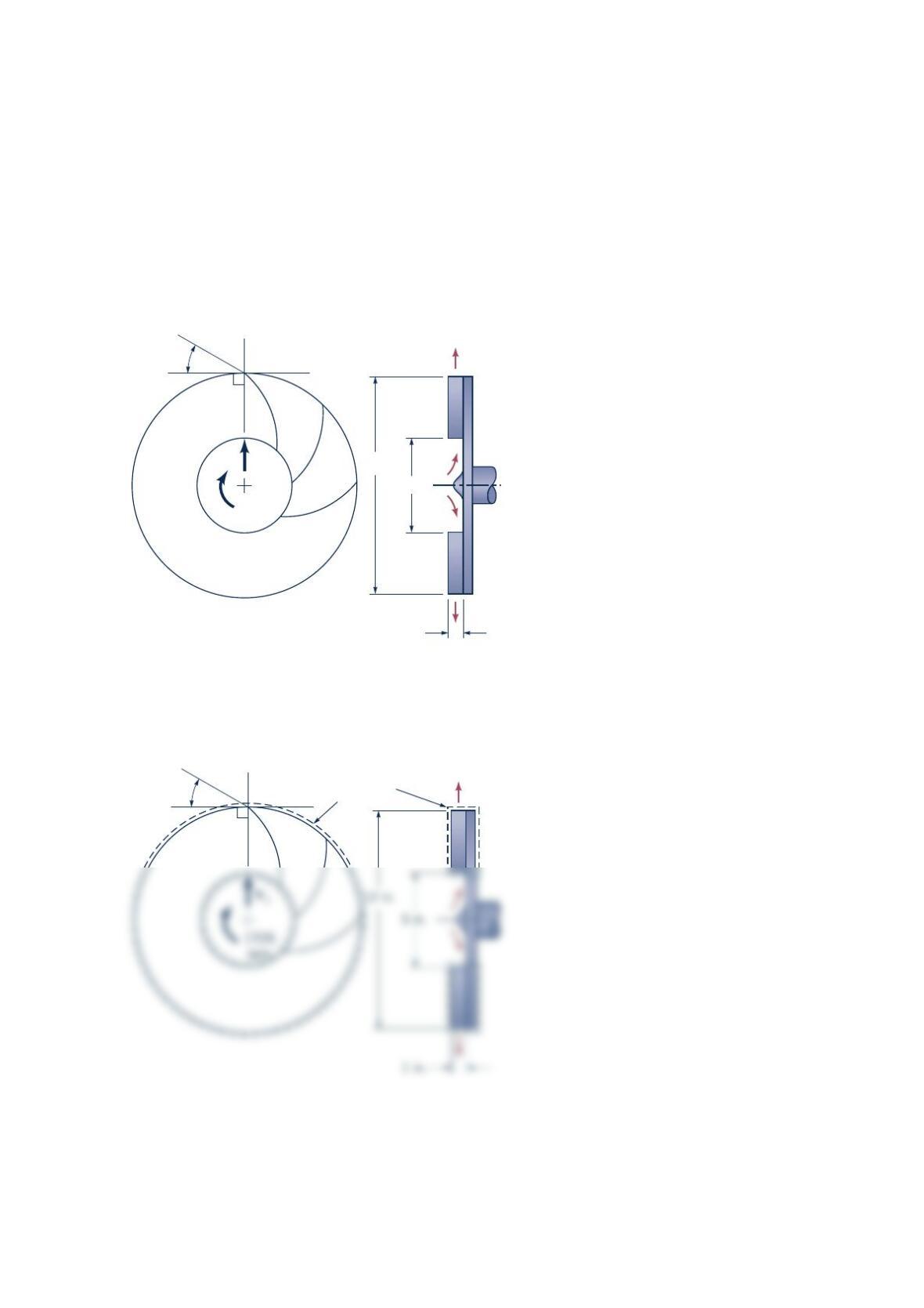
A fan (see the figure below) has a bladed rotor of 12-in. outside diameter and 5-in. inside
diameter and runs at 1725rpm . The width of each rotor blade is 1 in. from blade inlet to
outlet. The volume flowrate is steady at 3
230 ft /min , and the absolute velocity of the air at
blade inlet, 1
V
, is purely radial. The blade discharge angle is 30 measured with respect to
the tangential direction at the outside diameter of the rotor. (a) What would be a
reasonable blade inlet angle (measured with respect to the tangential direction at the inside
diameter of the rotor)? (b) Find the power required to run the fan.
Solution 5.86
V1
1725
rpm
Q = 230 ft3/min
1 in.
5 in.
12 in.
30°
Q
= 230 ft
3
/min
30°
Control
volume
The stationary and nondeforming control volume shown in the sketch above is used. To
determine a reasonable blade inlet angle, we assume that the blade should be tangent to the
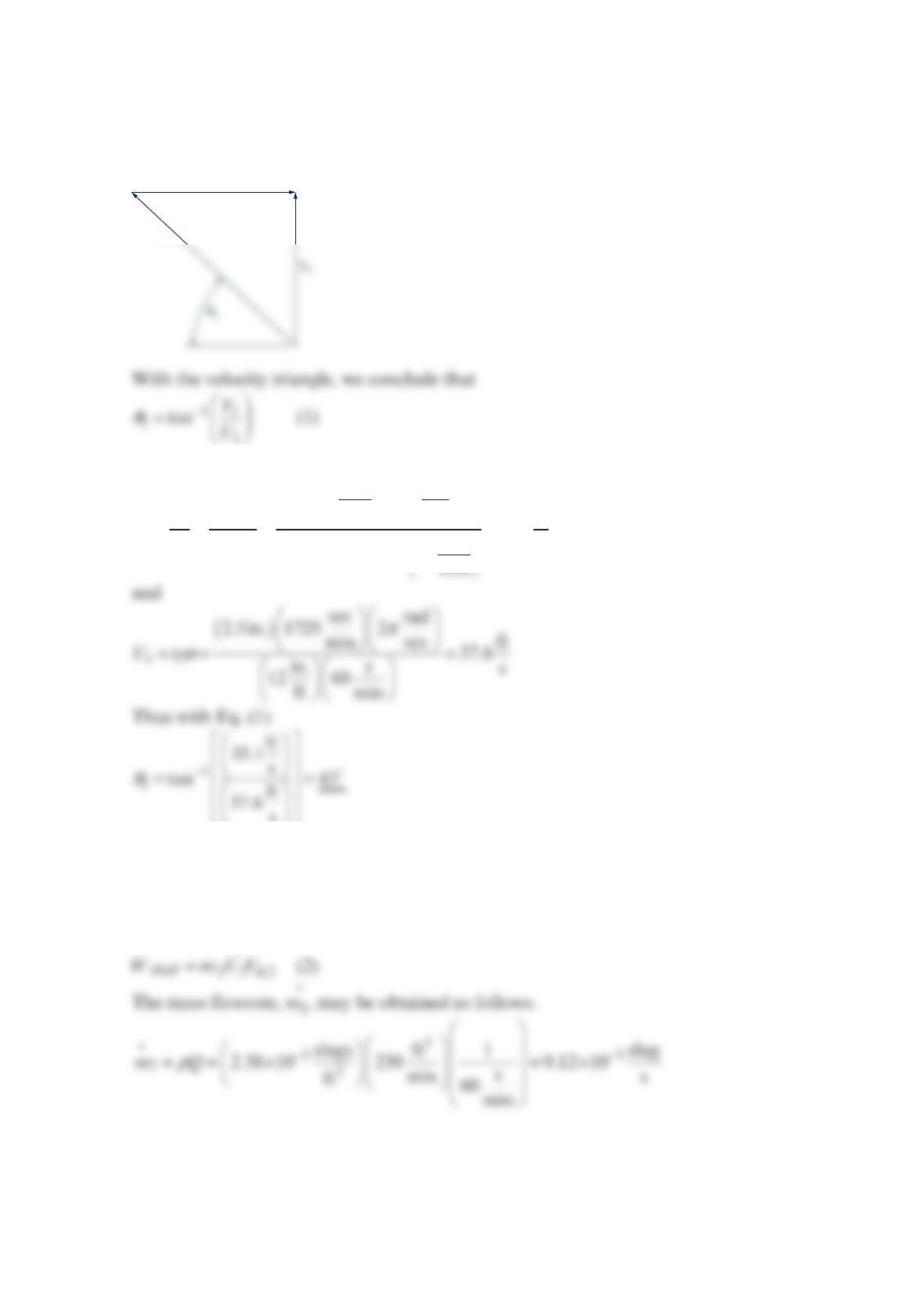
relative velocity at the inlet. The inlet velocity triangle is sketched below.
Now
()()
ππ
== = =
1
32
2
1
111
ft m
230 144
min ft ft
35.1
s
2s
22.5in. in.60
QQ
VArh
The power required, shaft
W
, may be obtained with the equation
()( )
shaft out
in in in out out
WmUVmUV
θθ
=− ± + ±
Thus
U
1
W
1
Also
The value of ,2
V
θ
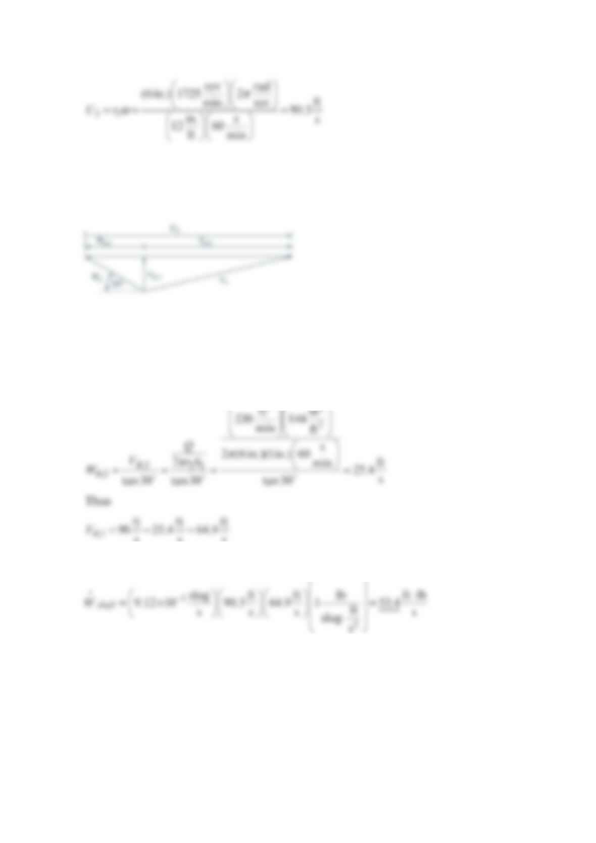
may be obtained by considering the velocity triangle for the flow leaving
the rotor at section (2). The relative velocity at the rotor exit is considered to be tangent to
the blade there. The rotor exit flow velocity triangle is sketched below.
Now
θθ
=−
,2 2 ,2
32
and
VUW
sss
and from Eq. (2)
Problem 5.87
Calculate the torque required to drive the pump shown in the figure below at 30Hz and to
deliver 20 C
water at 3
3.0 m /min .
Solution 5.87
GIVEN: Pump in the figure in the problem, rotates at 30 Hz and delivers water at
3
3.0 m / min ,
θθ
= = = = =
1212 2
0.065 m, 0.13 m, 3.0 cm, 1.0 cm, =30 , and 45 , 20 C.RRbb
FIND: Required torque.
SOLUTION: The absolute velocity 1
V
is found from
22 2 222 2
3
or
mmin
3.0 min 60s m
Q
Impeller
ω
θ
1
R
2 =
0.13 m
b
2 = 1.0 cm
b
1 =
3.0 cm
R
1 =
0.065 m
Absolute
velocity,
V
1
Absolute velocity,
V
2
, T
30° =
θ
2= 45°
V
where
==
torque on pump impeller,
z
TT
The angular momentum equation is then
()
22 2 11 1
For 20 C
water,
Problem 5.88
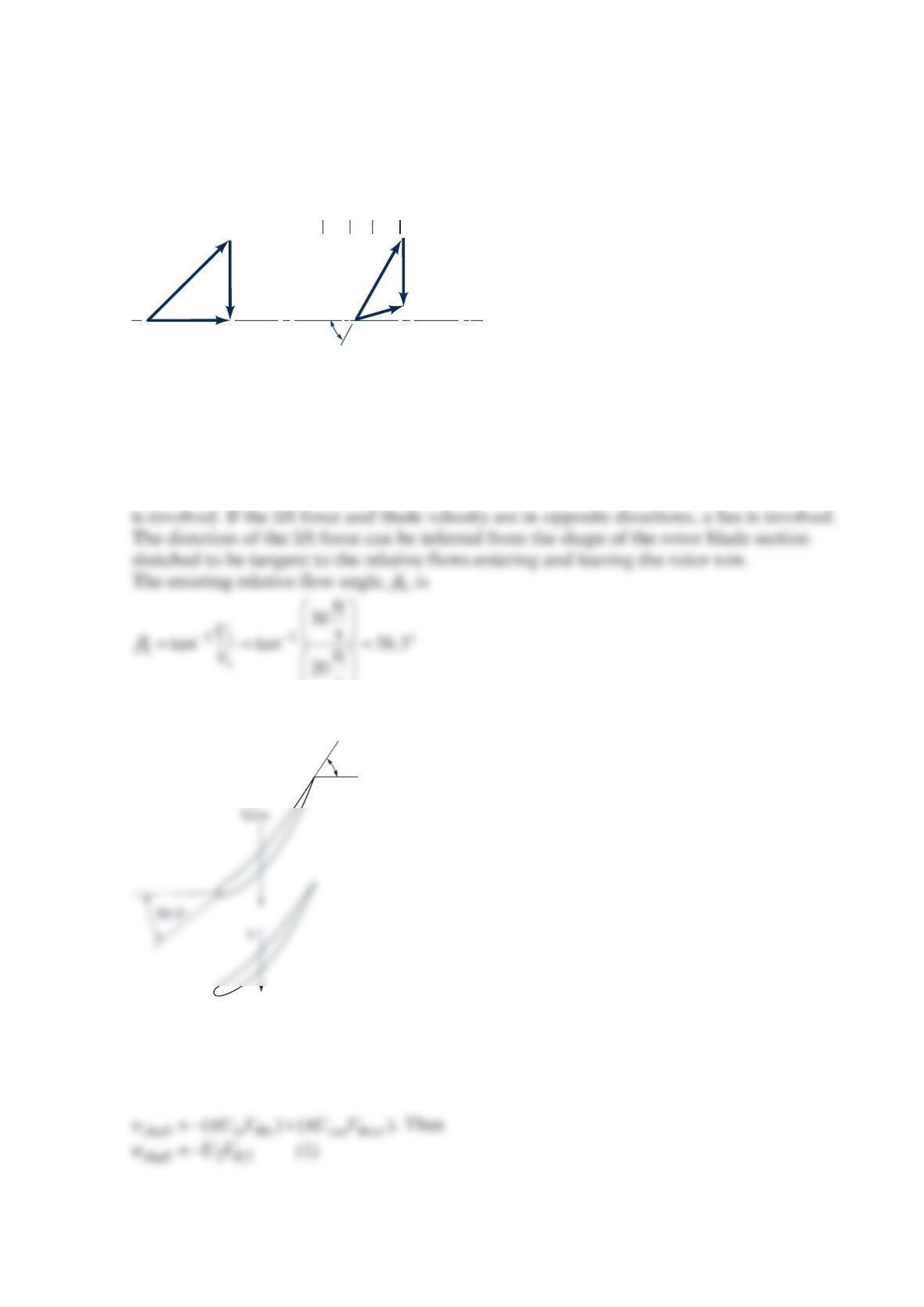
An axial flow turbomachine rotor involves the upstream (1) and downstream (2) velocity
triangles shown in the figure below. Is this turbomachine, a turbine or a fan? Sketch an
appropriate blade section and determine energy transferred per unit mass of fluid.
Solution 5.88
We can determine whether the axial flow turbomachine involved is a turbine or a fan by
comparing the direction of the lift force on the rotor blade section with the direction of the
blade velocity, .
U
If the lift force and the blade velocity are in the same direction, a turbine
Thus, the rotor blade sections sketched below are appropriate.
Since the lift force acting on each rotor blade section is in the same direction as the blade
velocity, we conclude that this turbomachine is a turbine. The energy transferred per unit
mass is the shaft work per unit mass, shaft
w, which we can determine with the equation
U1= 30 ft/s
V1= 20 ft/s
=
60°
U2= 30 ft/s
W1
W1W2
1
W2
Lift
60°
From the velocity triangles, we obtain
θ
=−
,2 2 2
sin60
and
VW U
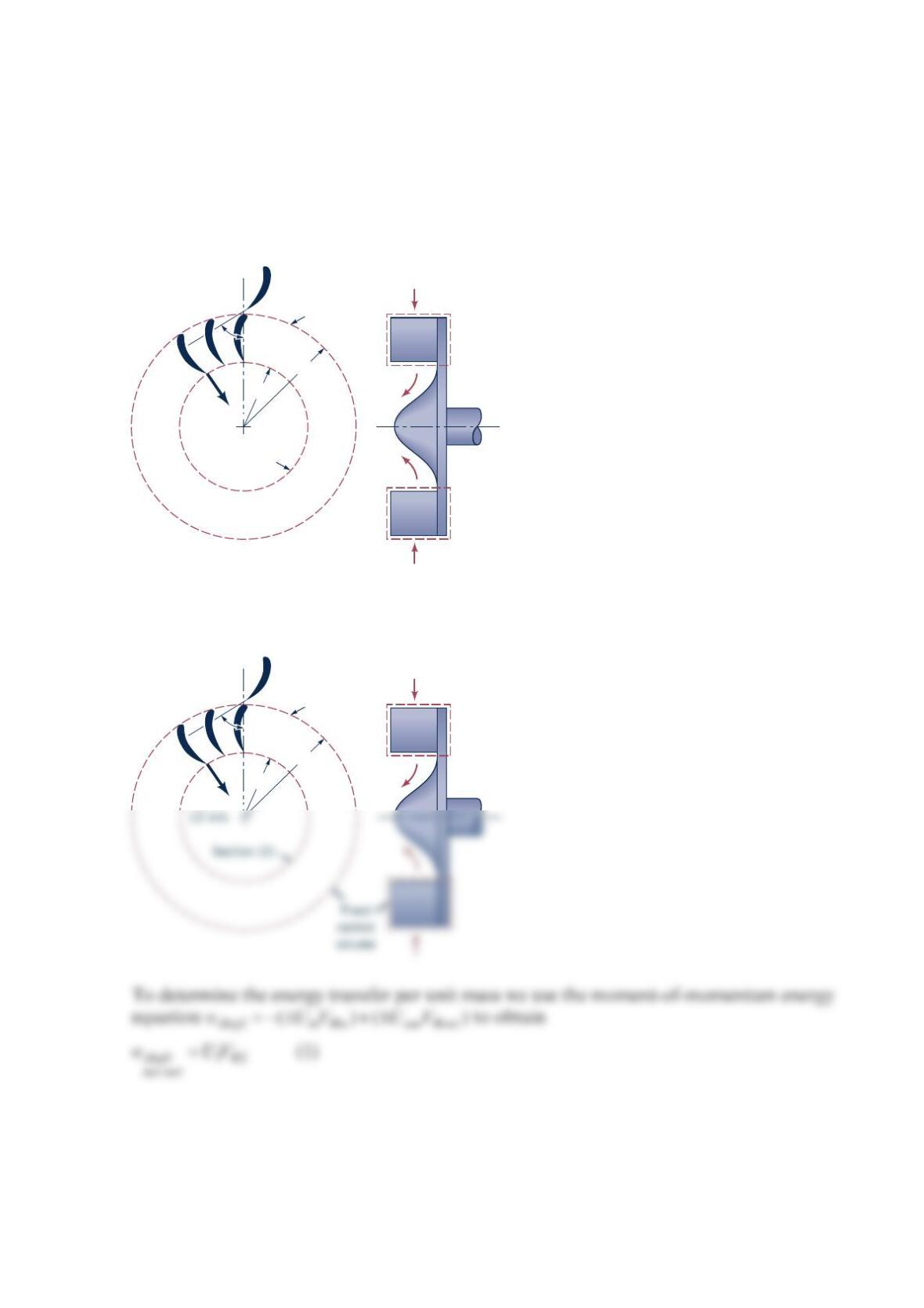
Problem 5.89
An inward flow radial turbine (see the figure below) involves a nozzle angle, 1
α
, of 60° and
an inlet rotor tip speed, 1
U
, of 6 m/s. The ratio of rotor inlet to outlet diameters is 1.8. The
absolute velocity leaving the rotor at section (2) is radial with a magnitude of 12 m/s.
Determine the energy transfer per unit mass of fluid flowing through this turbine if the fluid
is (a) air, (b) water.
Solution 5.89
V2 =
12 m/s
r2
r1
Section (2)
Section (1)
1
α
V2 =
r2
r1
Section (1)
1
α