Problem 5.72
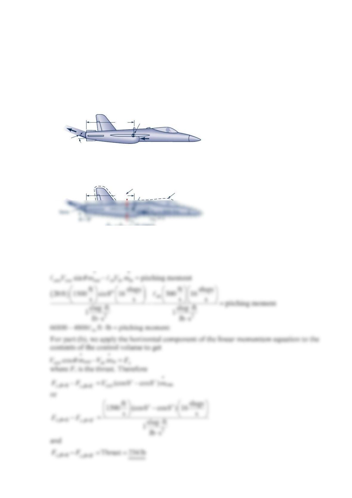
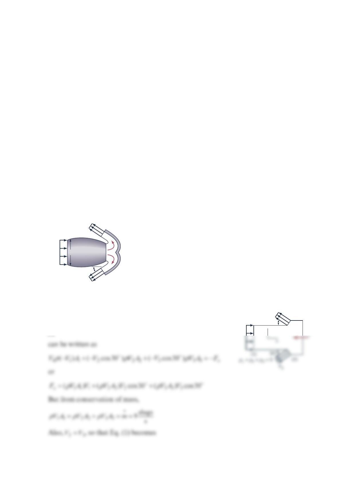
Thrust vector control is a technique that can be used to greatly improve the
maneuverability of military fighter aircraft. It consists of using a set of vanes in the exit of a
jet engine to deflect the exhaust gases as shown in the figure below. (a) Determine the
pitching moment (the moment tending to rotate the nose of the aircraft up) about the
aircraft’s mass center (cg) for the conditions indicated in the figure. (b) By how much is the
thrust (force along the centerline of the aircraft) reduced for the case indicated compared to
normal flight when the exhaust is parallel to the centerline?
Solution 5.72
For part (a), we apply the component of the moment-of-momentum equation that is
perpendicular to the plane of the sketch of the aircraft to the content of the control volume
shown to get
θ
= 8°
Vane
p
out
= 0
Vout
= 1500 ft/s 20 ft
cg
Vin
= 300 ft/s
pin
= 0
m
•
in
=
m
•
out
= 16 slugs/s
p
out
= 0
V
out
= 1500 ft/s 20 ft cg
CV
m
in
= m
out
= 16 slugs/s
ℓ
out
Problem 5.73
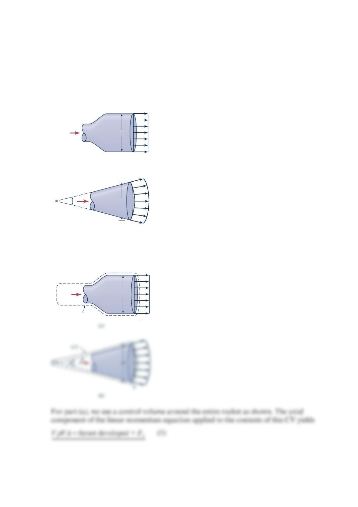
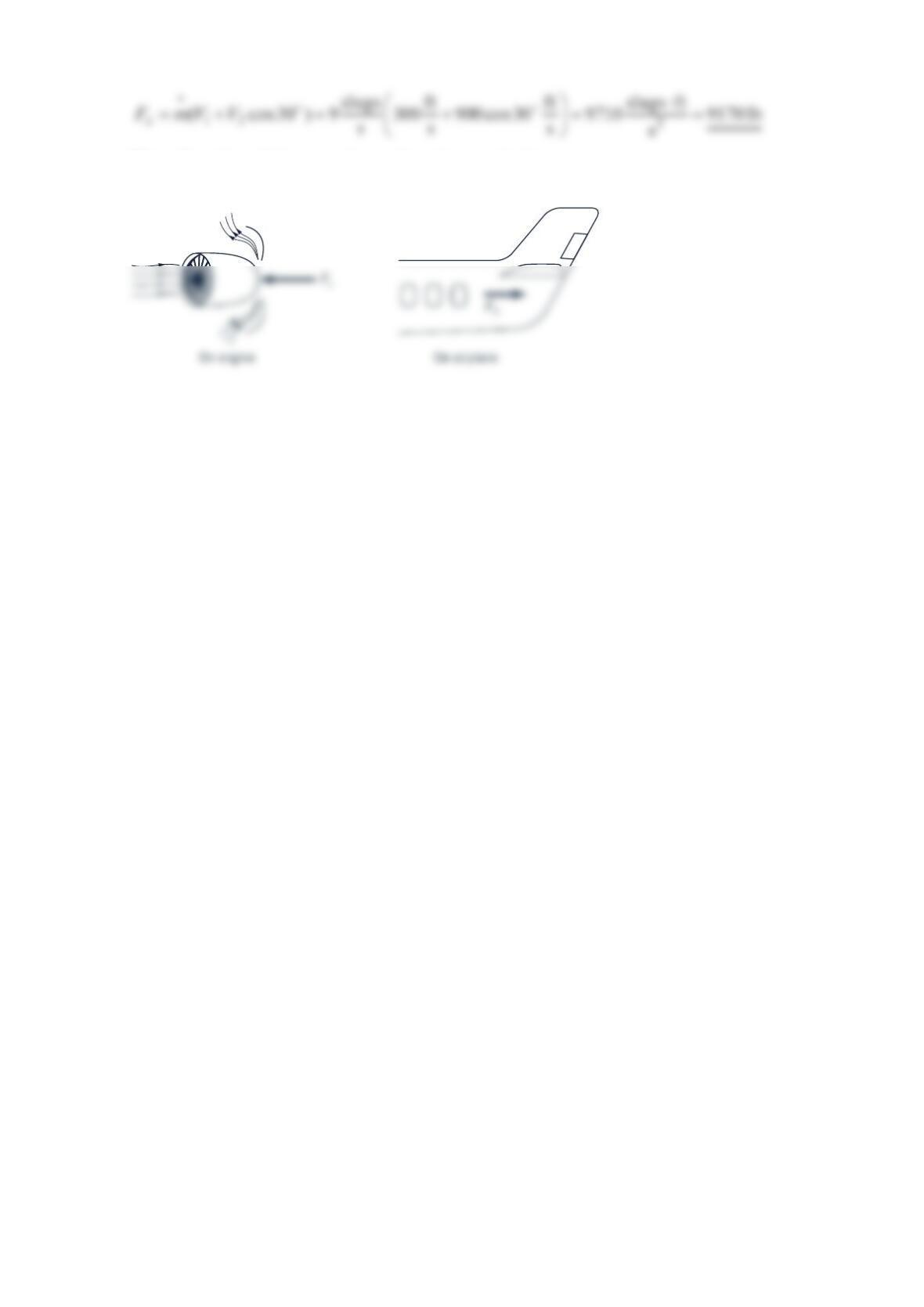
The exhaust gas from the rocket as shown in the figure (a) below leaves the nozzle with a
uniform velocity parallel to the x axis. The gas is assumed to be discharged from the nozzle as
a free jet. (a) Show that the thrust that is developed is equal to 2
AV
ρ
, where 2
/
4
A
D
π
=. (b)
The exhaust gas from the rocket nozzle shown in the figure (b) below is also uniform, but
rather than being directed along the x axis, it is directed along rays from point 0 as indicated.
Determine the thrust for this rocket.
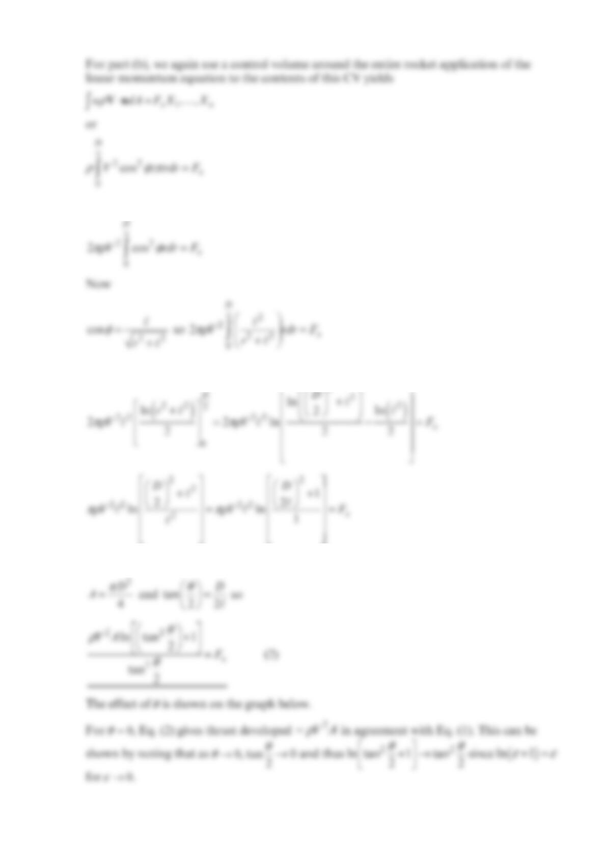
Solution 5.73
O
D
D
(
a
)
(
b
)
m
•
m
•
θ
V
V
D
m
•
V
CV
and
and
2
Now
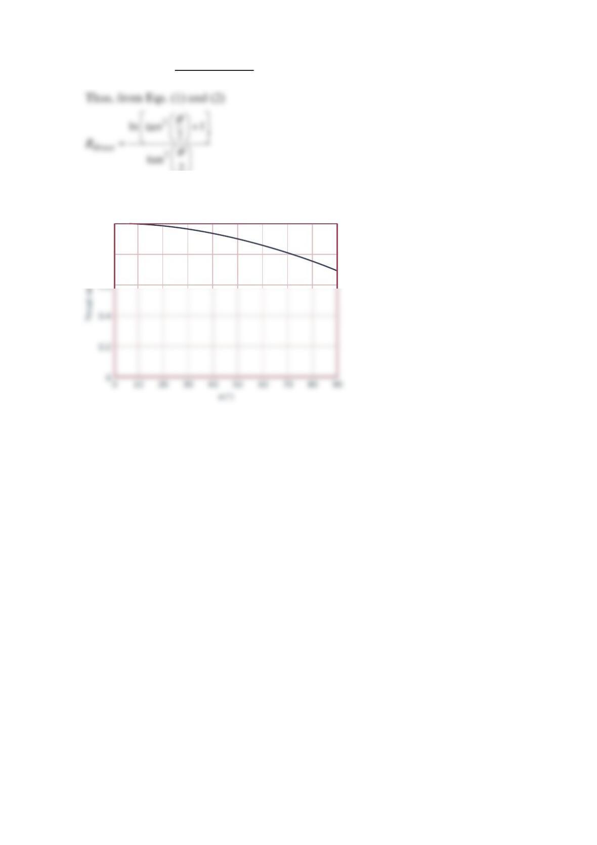
thrust for 0
Let thrust ratio thrust for 0 thrust
R
θ
θ
≠
==
=
2
This result is plotted.
0.8
1
Thrust ratio
Problem 5.74
Where the plume goes Commercial airliners have wheel brakes very similar to those on
highway vehicles. In fact, antilock brakes now found on most new cars were first developed
for use on airplanes. However, when landing, the major braking force comes from the
engine rather than the wheel brakes. Upon touchdown, a piece of engine cowling translates
aft and blocker doors drop down, directing the engine airflow into a honeycomb structure
called a cascade. The cascade reverses the direction of the high-speed engine exhausts by
nearly 180° so that it flows forward. As predicted by the momentum equation, the exhaust
passing through this system produces a substantial braking force—the reverse thrust.
Designers must know the flow pattern of the exhaust plumes to eliminate potential
problems. For example, the plumes of hot exhaust must be kept away from parts of the
aircraft where repeated heating and cooling could cause premature fatigue. Also the plumes
must not reenter the engine inlet, blow debris from the runway in front of the engine, or
envelop the vertical tail. (See Problem 5.74.)
Air flows into the jet engine shown in the figure below at a rate of 9slugs/s and a speed of
300 ft/s . Upon landing, the engine exhaust exits through the reverse thrust mechanism with
a speed of 900 ft/s in the direction indicated. Determine the reverse thrust applied by the
engine to the airplane. Assume the inlet and exit pressures are atmospheric and that the
mass flowrate of fuel is negligible compared to the air flowrate through the engine.
Solution 5.74
The momentum equation (x-component),
x
C
S
udAF
ρ
⋅=
Vn , for the control volume shown
4-ft diameter
30°
(1)
(3)
(2)
V
1
= 300 ft/s
V
2
= 900 ft/s
V
3
= 900 ft/s
F
30°
(3)
V
3
V
1
y
Note direction of x
F
on engine and engine on airplane.
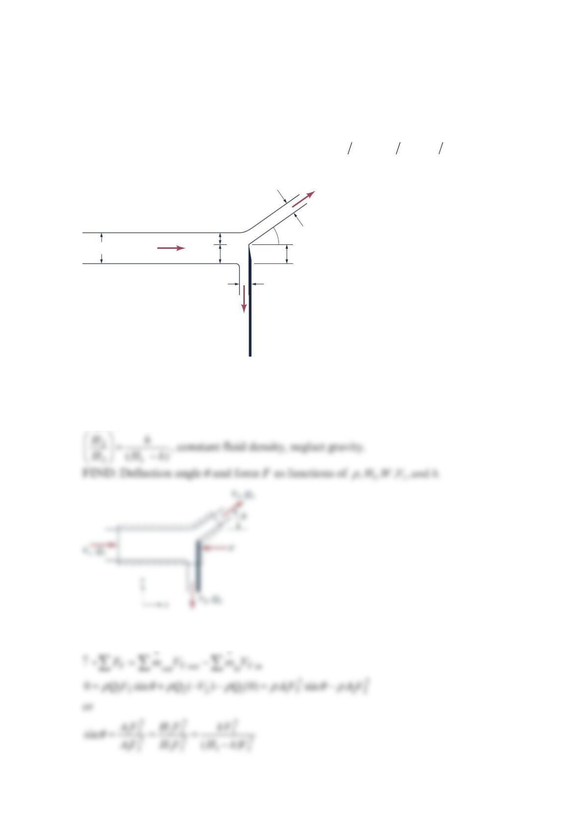
Problem 5.75
The figure below shows a sharp-edged splitter plate used to control the flow of a liquid jet
W
units wide by 1
H units high. Write expressions for the deflection angle
θ
and the force
F
of the jet on the splitter plate as a function of the fluid density 1
,,,HWV
ρ
, and plate
insertion
h
. This force
F
has no components parallel to the plate. Assume that the jet flow
is inviscid, that the jet width
W
remains constant, ′′
==−
23 23 1
( )HH HH hH h
, and
constant fluid density.
Solution 5.75
GIVEN: The figure below, sharp-edged splitter splits jet of area 11
A
WH=. Fluid density
ρ
,
and plate insertion
h
, inviscid flow and constant jet width
W
, no force component parallel
to plate.
SOLUTION: Apply the linear momentum equation in the x-direction for steady state
condition for a control volume around the flow.
V
V
V
A
1 =
WH
1
H
3
′
H
2
′
h
A
2 =
WH
2
p
atm
p
atm
p
atm
A
3 =
WH
3
θ
θ
F
Applying conservation of mass to the lower portion of the jet and the upper portion of the
stream gives
′′
= =
21 22 31 33
,,
HV HV HV HV
Now apply the linear momentum equation to the control volume in the y-direction. For
steady state,
11
We now apply the mechanical energy equation to the upper stream. Since the flow is given
as inviscid, we get
1
Since the continuity equation for the upper stream gives
′=
′
==−
31 33
331
,
we get
HV HV
HHHh
so
h
H
1
–
h
Problem 5.76
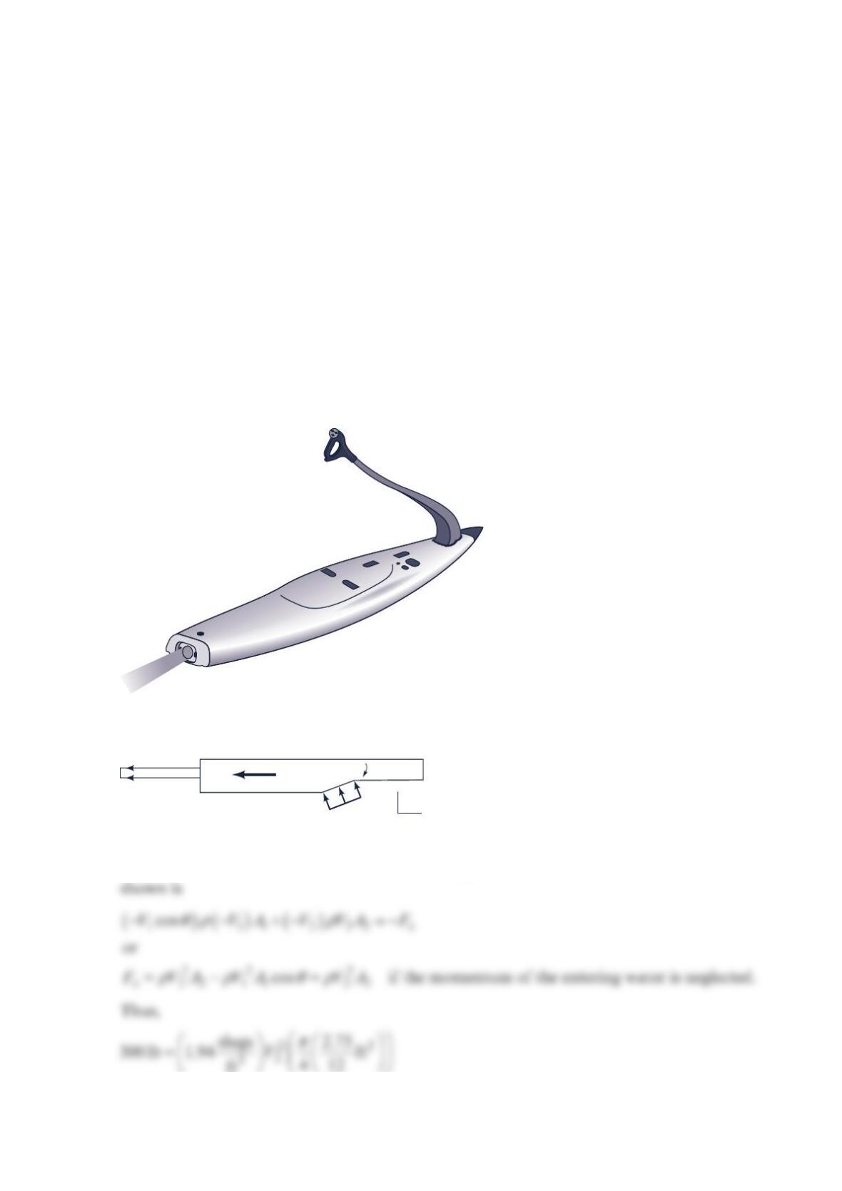
Motorized surfboard When Bob Montgomery, a former professional surfer, started to
design his motorized surfboard (called a jet board), he discovered that there were many
engineering challenges. The idea is to provide surfing to anyone, no matter where they live,
near or far from the ocean. The rider stands on the device like a surfboard and steers it like
a surfboard by shifting his or her body weight. A new, sleek, compact 45-hp engine and
pump was designed to fit within the surfboard hull. Thrust is produced in response to the
change in linear momentum of the water stream as it enters through the inlet passage and
exits through an appropriately designed nozzle. Some of the fluid dynamic problems
associated with designing the craft included one-way valves so that water does not get into
the engine (at both the intake or exhaust ports), buoyancy, hydrodynamic lift, drag, thrust,
and hull stability. (See Problem 5.76.)
The thrust to propel the powered surfboard shown in the figure below is a result of water
pumped through the board that exits as a high-speed 2.75-in.-diameter jet. Determine the
flowrate and the velocity of the exiting jet if the thrust is to be 300 lb . Neglect the
momentum of the water entering the pump.
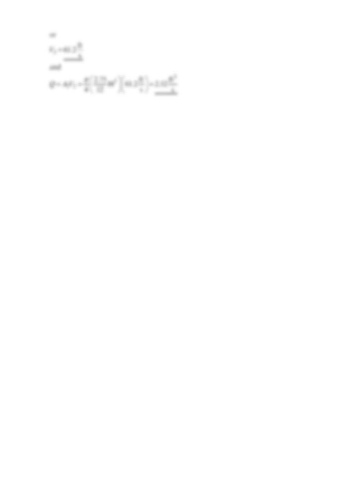
Solution 5.76
The x-component of the momentum equation, x
C
S
udAF
ρ
⋅=
Vn , for the control volume
V
2
p
1 =
p
2
F
x
V
1
(2)
(1)
θ
y
x
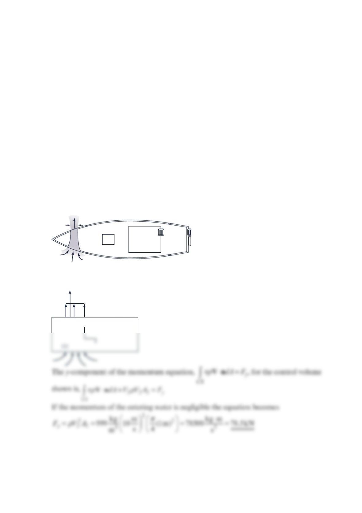
Problem 5.77
Bow thrusters In the past, large ships required the use of tugboats for precise maneuvering,
especially when docking. Nowadays, most large ships (and many moderate to small ones as
well) are equipped with bow thrusters to help steer in close quarters. The units consist of a
mechanism (usually a ducted propeller mounted at right angles to the fore/aft axis of the
ship) that takes water from one side of the bow and ejects it as a water jet on the other side.
The momentum flux of this jet produces a starboard or port force on the ship for
maneuvering. Sometimes a second unit is installed in the stern. Initially used in the bows of
ferries, these versatile control devices have become popular in offshore oil servicing boats,
fishing vessels, and larger oceangoing craft. They permit unassisted maneuvering alongside
of oil rigs, vessels, loading platforms, fishing nets, and docks. They also provide precise
control at slow speeds through locks, narrow channels, and bridges, where the rudder
becomes very ineffective. (See Problem 5.77.)
The bow thruster on the boat shown in the figure below is used to turn the boat. The
thruster produces a 1-m-diameter jet of water with a velocity of 10 m/s . Determine the
force produced by the thruster. Assume that the inlet and outlet pressures are zero and that
the momentum of the water entering the thruster is negligible.
Solution 5.77
V
= 10 m/s
D
= 1 m
(2)
y
V
2
F
y
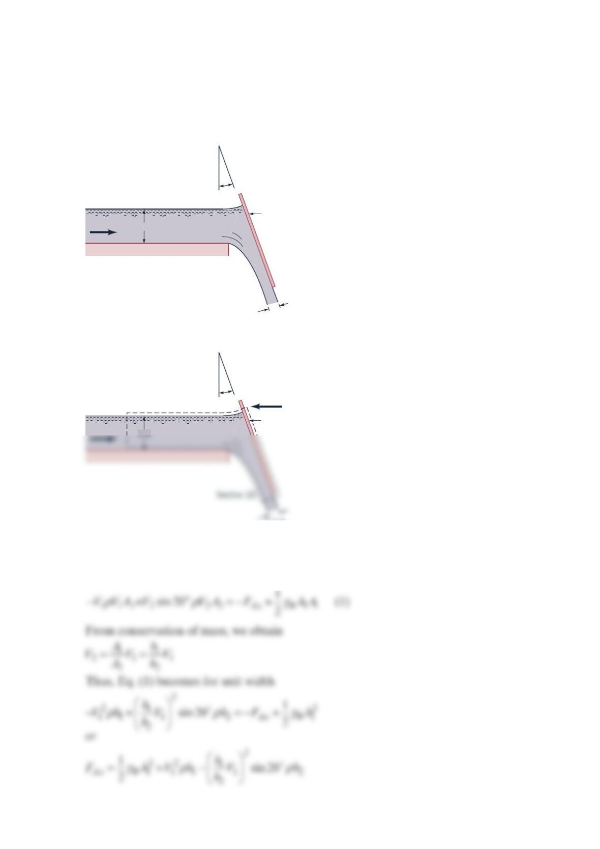
Problem 5.78
Water flows from a two-dimensional open channel and is diverted by an inclined plate as
illustrated in the figure below. When the velocity at section (1) is 10 ft/s , what horizontal
force (per unit width) is required to hold the plate in position? At section (1), the pressure
distribution is hydrostatic, and the fluid acts as a free jet at section (2). Neglect friction.
Solution 5.78
A control volume that contains most of the plane and the water being turned by the plate as
shown in the sketch above is used. Application of the horizontal x-direction component of
the linear momentum equation yields
10 ft/s
Section (2)
Plate
4 ft
1.0 ft
Section (1) 20°
10 ft/s
Plate
1.0 ft
Section (1) 20°
FAx
Then
Problem 5.80
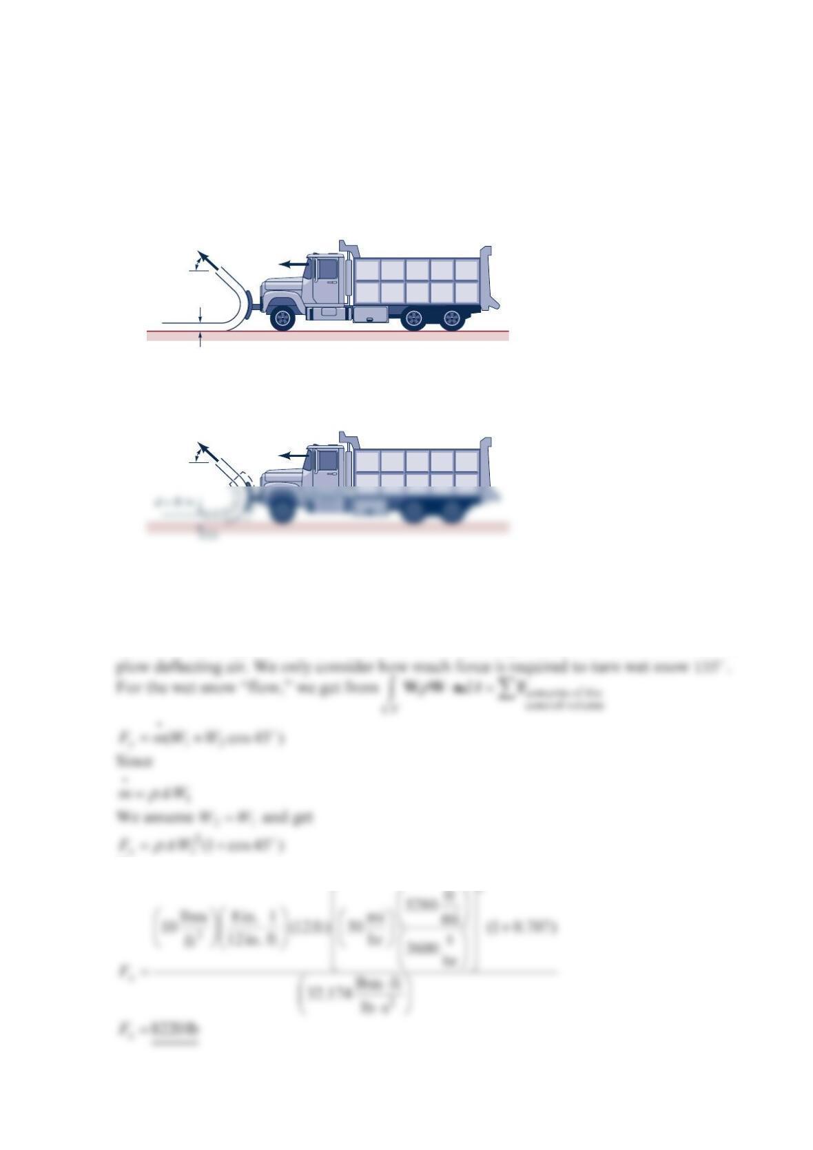
A snowplow mounted on a truck clears a path 12 ft through heavy wet snow, as shown in
the figure below. The snow is 8in. deep and its density is 3
10 lbm/ft . The truck travels at
30 mph. The snow is discharged from the plow at an angle of 45 from the direction of
travel and 45 above the horizontal, as shown in the figure below. Estimate the force
required to push the plow.
Solution 5.80
To estimate the force required to push the snowplow, we use the control volume shown in
the sketch above and the equation contents of the
control volume
C
V
dA
ρ
⋅=
WWn F . We neglect the friction
force between the plow and the road surface. We also neglect any force associated with the
C
ρ
Then
2
= 45°
(in plane of blade)
d = 8 in.
U = 30 mph
θ
= 45°
(in plane of blade)
U = 30 mph
θ
(2)
Problem 5.81
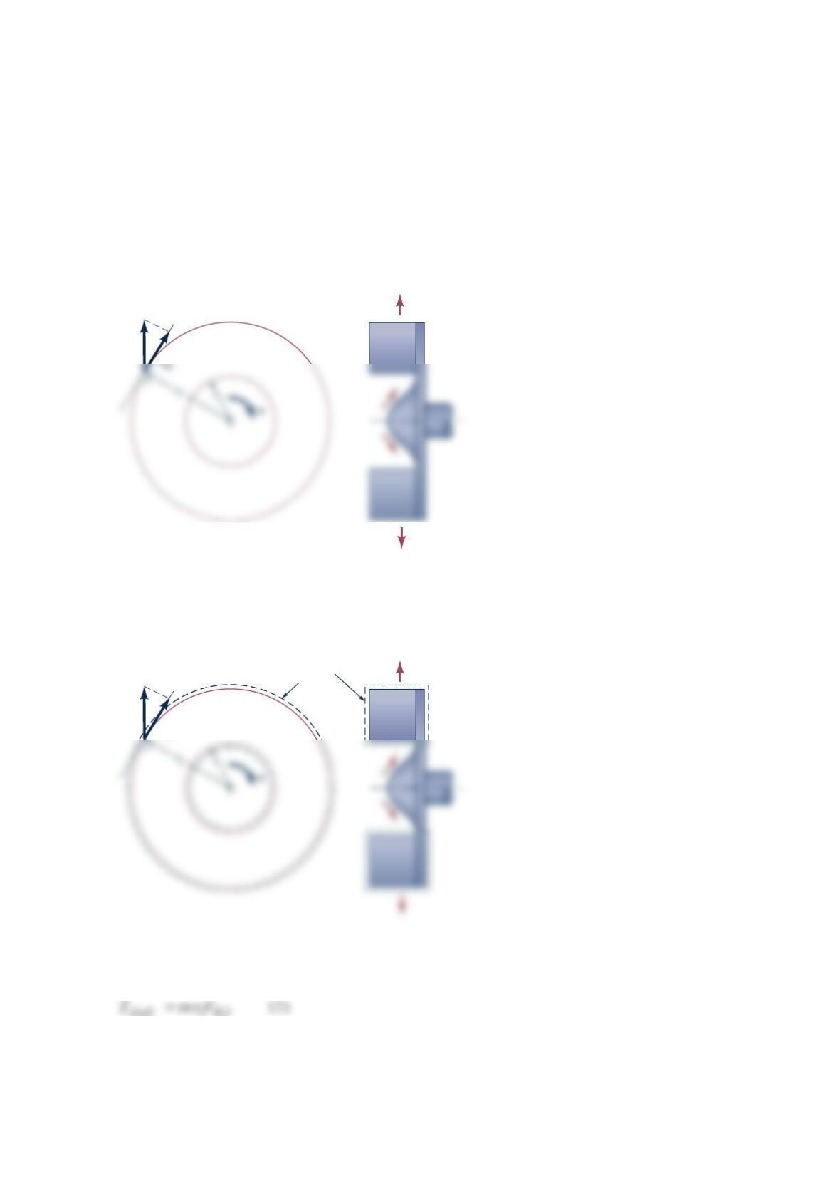
An incompressible fluid flows outward through a blower as indicated in the figure below.
The shaft torque involved, shaft
T, is estimated with the following relationship:
2,2
shaft
TmrV
θ
=
where m
= mass flowrate through the blower,
2
r= outer radius of blower, and ,2
V
θ
=
tangential component of absolute fluid velocity leaving the blower. State the flow
conditions that make this formula valid.
Solution 5.81
The flow conditions that make
V
2
V
2
V
,2
θ
Control
volume
valid may be identified by comparing Eq. (1) with the axial component of the equation
()
dV
t
ρ
∂×
∂rV
()
contents of the
control volume
CV CS
dA
ρ
+× ⋅=×
rV Vn rF These conditions are
(a) stationary and nondeforming control volume (see sketch above)
Problem 5.82
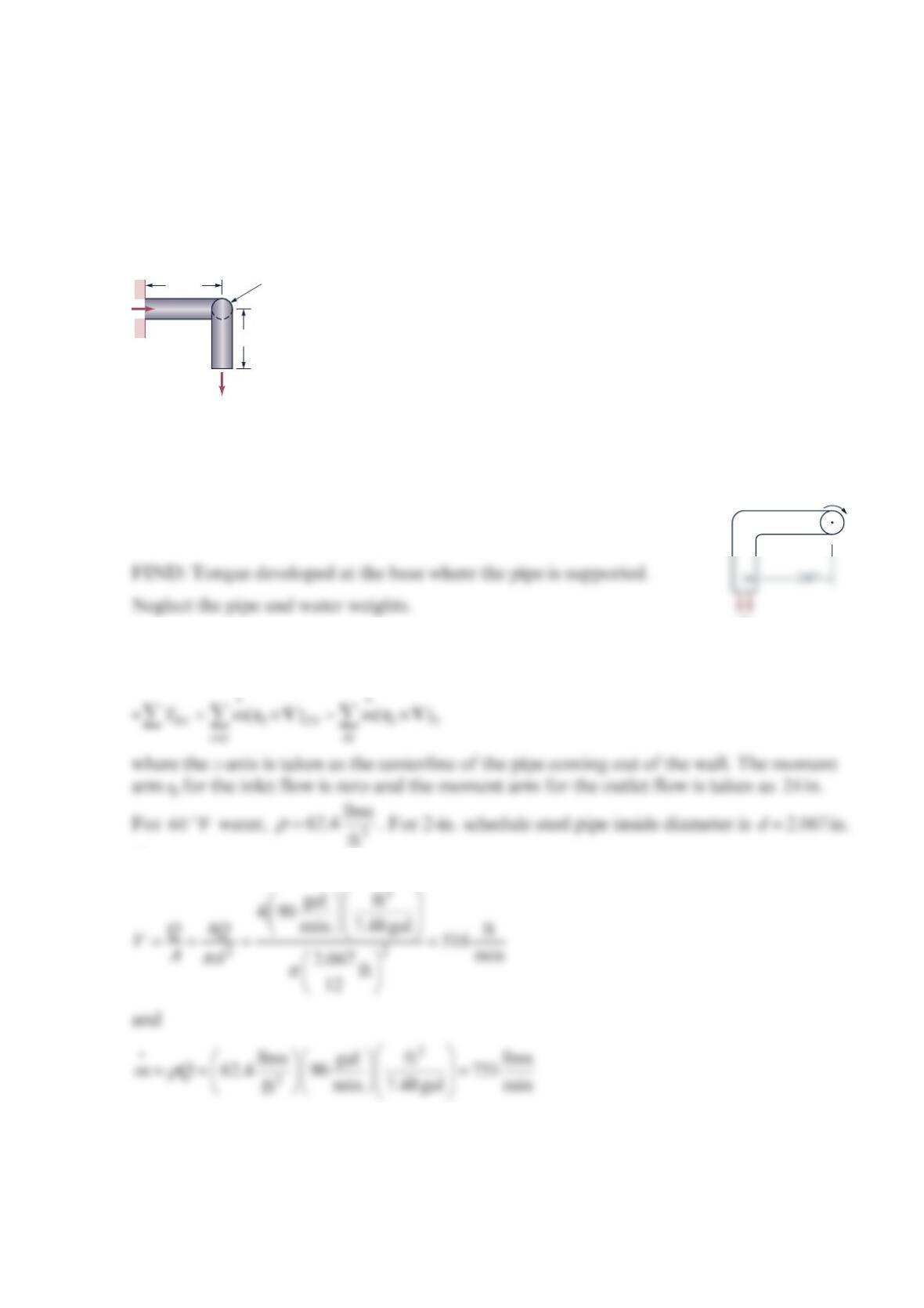
Water at 60 °F is flowing through the 2-in. schedule 40 steel pipe shown in the figure below
at the rate of 90 gal/min . Determine the torque developed at the base where the pipe is
supported. Neglect the pipe and water weights. Steady-state conditions apply.
Solution 5.82
GIVEN: Water is flowing through a 2-in., schedule 40 steel pipe
= ( 2.067 in.)d at the rate of 90 gal/min . 60 F
.
SOLUTION: Applying the angular momentum equation to a control
volume around the pipe gives
Then
13 in.
9.5 in.
Q
= 90 gal/min
Horizontal
section of
pipe is 24 in.
long.
Pipe
supported
by wall
V
z
+
Then
Problem 5.83
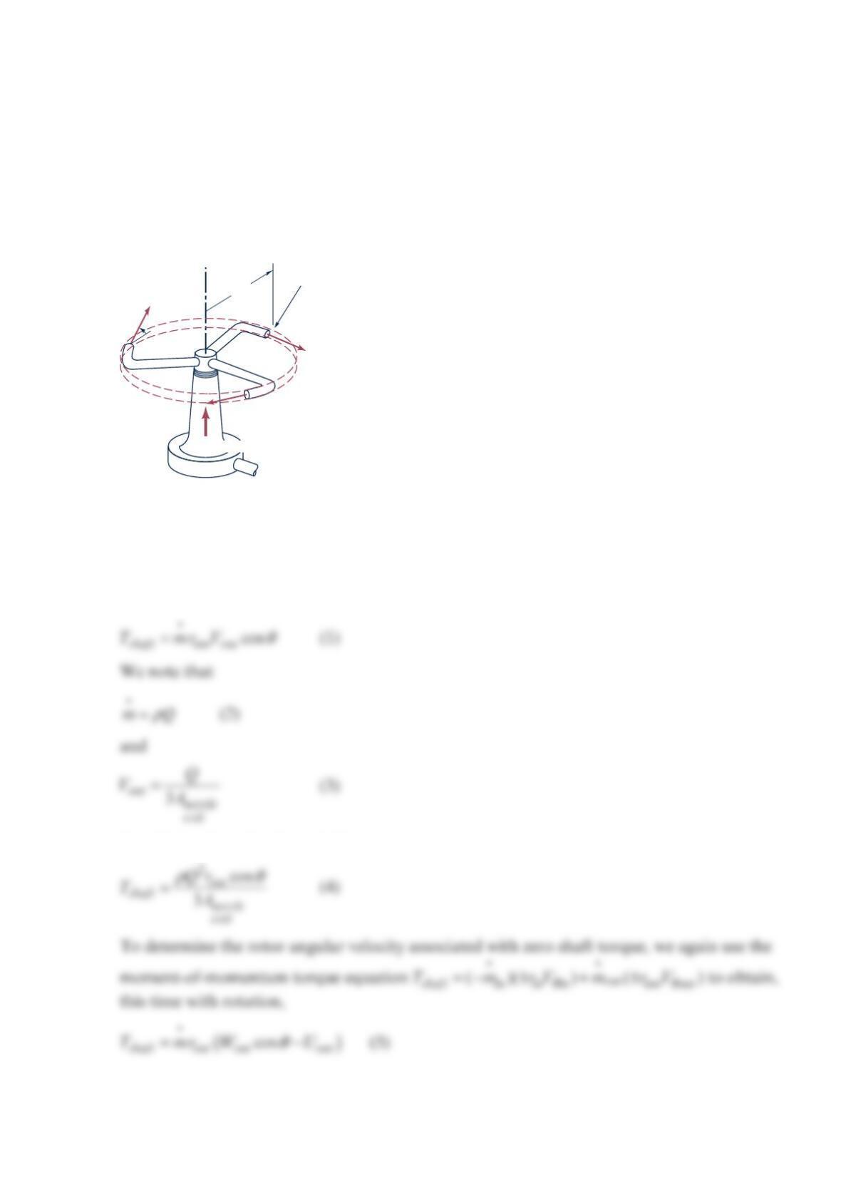
Five liters/second of water enters the rotor as shown in the figure below along the axis of
rotation. The cross-sectional area of each of the three nozzle exits normal to the relative
velocity is 2
18 mm . How large is the resisting torque required to hold the rotor stationary?
How fast will the rotor spin steadily if the resisting torque is reduced to zero and (a) 0
θ
=°
,
(b) 30
θ
=°
, (c) 60
θ
=°
?
Solution 5.83
To determine the torque required to hold rotor stationary, we use the moment-of-
momentum torque equation ()( ) ( )
out
shaft in in in out out
TmrVmrV
θθ
=− ± + ±
to obtain
Combining Eqs. (1), (2), and (3), we get
Q
= 5 l/s
r
= 0.5 m Nozzle exit area normal to
relative velocity = 18 mm
2
θ
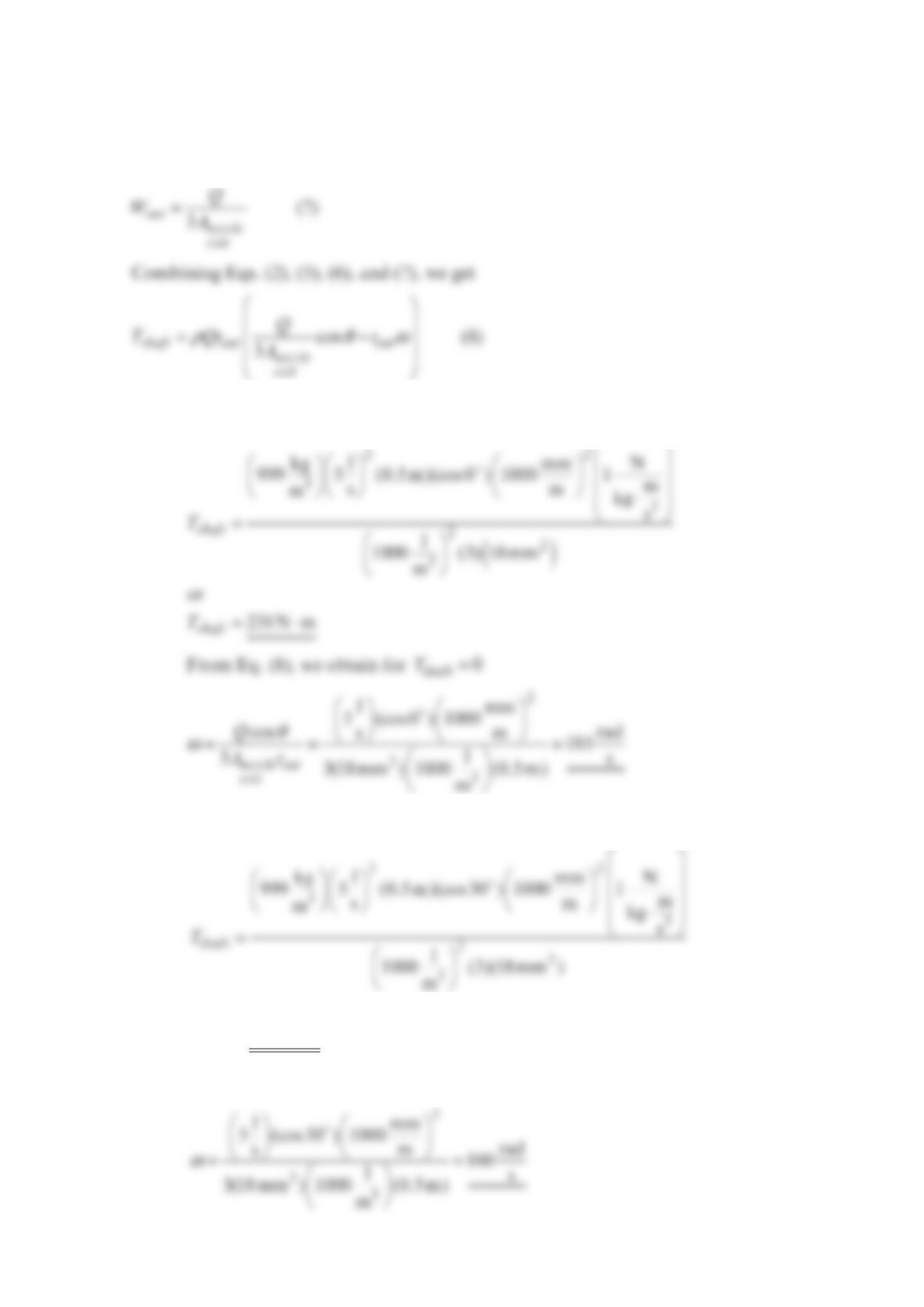
We note that
out out
U
r
ω
=
(6)
and
(a) For
θ
=0, we use Eq. (4) to get
(b) For
θ
=30, we use Eq. (4) to get
=⋅
shaft
or
200 N m
T
From Eq. (8), we obtain for 0
shaft
T=