Problem 5.127
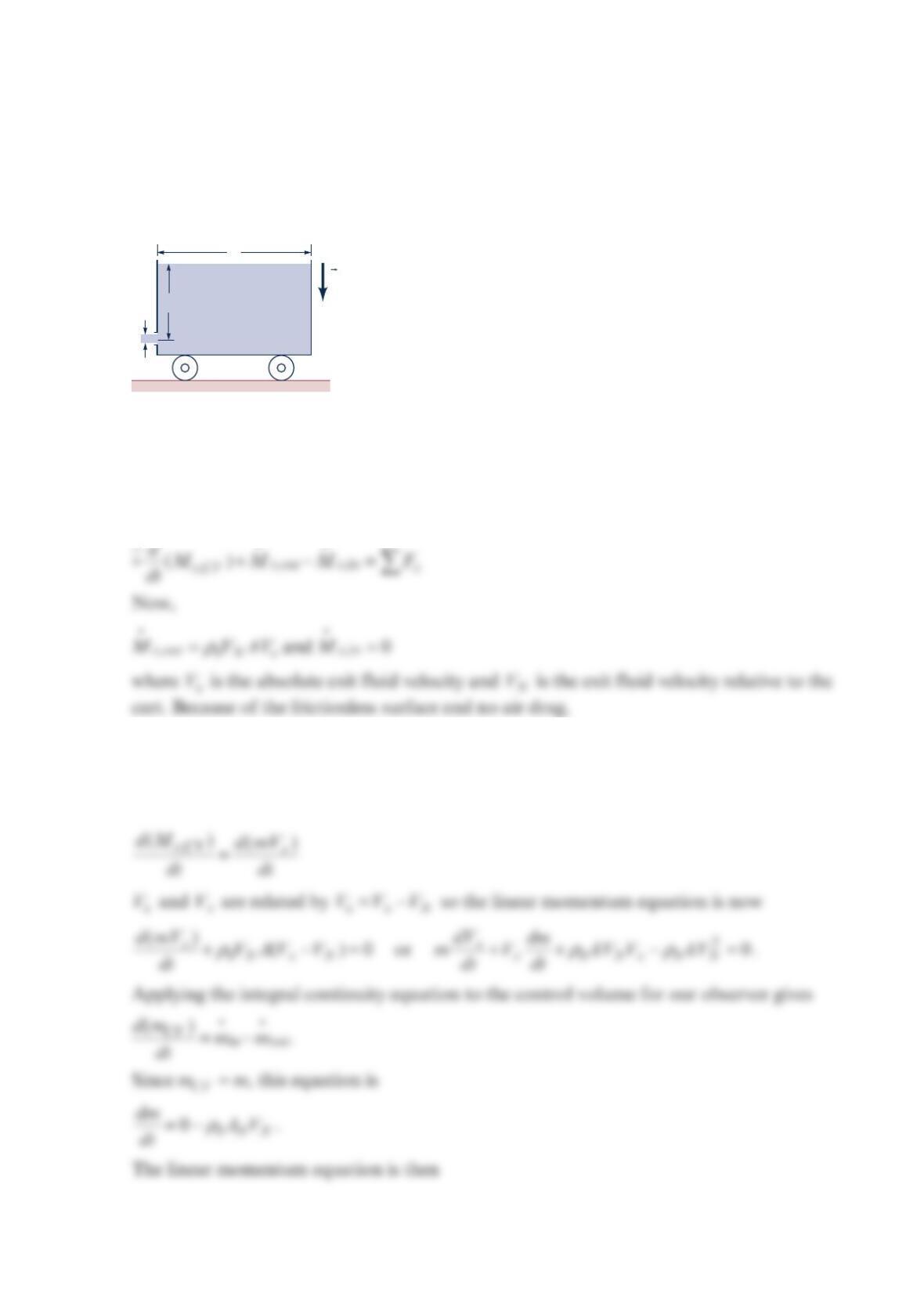
Find the acceleration of the cart shown in the figure below as a function of the water height
in the cart, which varies with time. The initial total mass is 0
m, and the fluid density is 0
ρ
.
Assume frictionless bearings, a frictionless surface, constant fluid density, uniform velocity
over area N
A
, all the fluid in the cart has the cart velocity, no air drag, and N
A
A.
Solution 5.127
Apply the linear momentum equation in the horizontal or x-direction for a control volume
moving with the cart. The observer and coordinate system are fixed on the ground.
=
0.
x
F
Denoting the mass of the cart and the fluid in the cart at time t by m and since all the fluid
in the cart has the cart velocity x
V, we get
ρ
h
0
= Initial fluid height
A
N
A
0
g
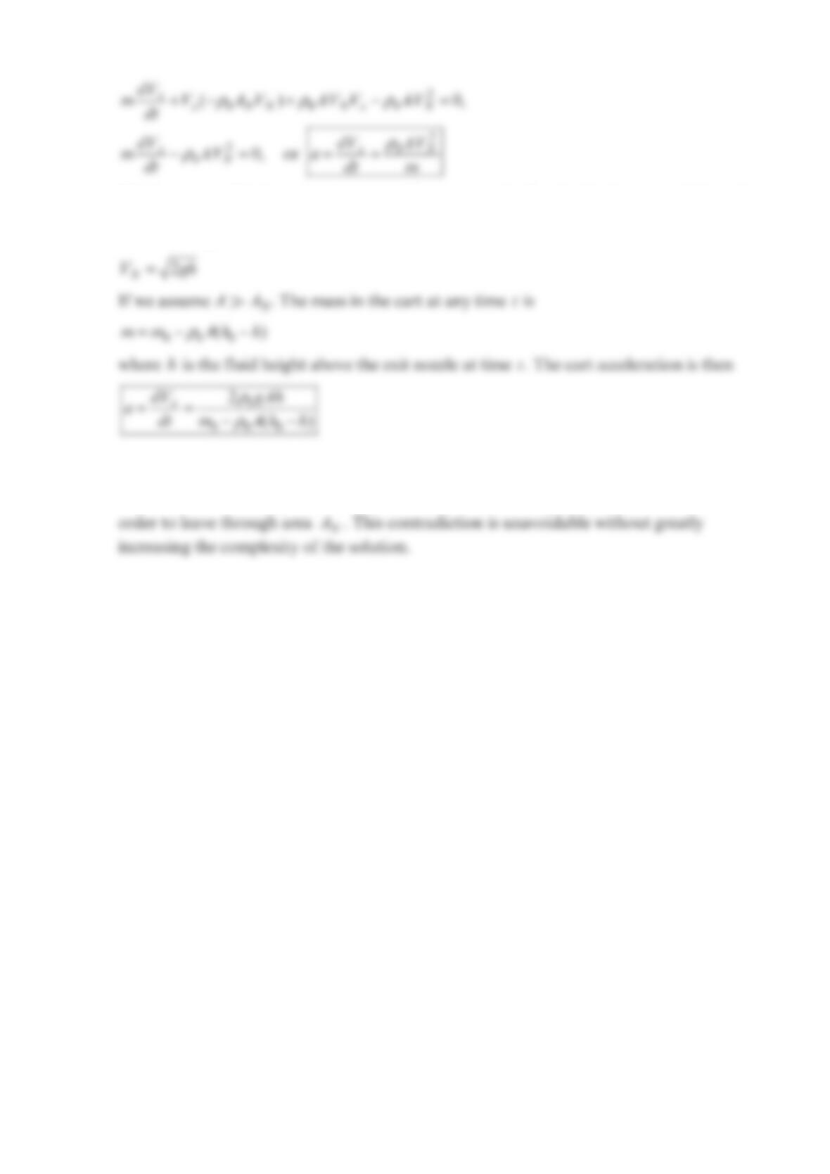
This is one possible from of the answer. If we assume the flow inside the cart and through
the nozzle is frictionless and assume we can write Bernoulli’s equation for an observer on
the cart, we get
Comment We have a small inconsistency. We assumed previously all the fluid in the cart
had the cart velocity x
V but some of the fluid in the cart must move relative to the cart in
Problem 5.128
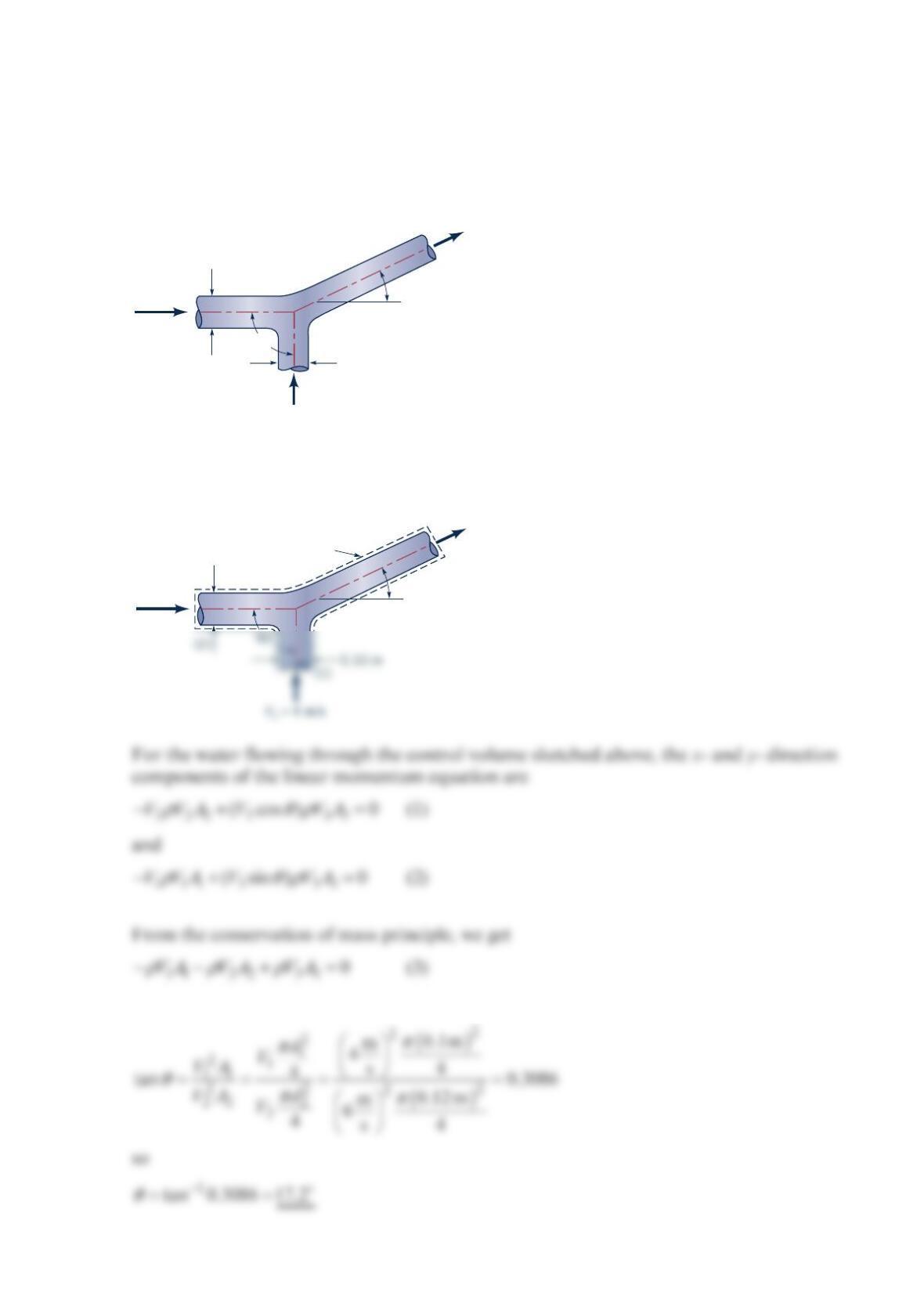
Two water jets collide and form one homogeneous jet as shown in the figure below. (a)
Determine the speed,
V
, and direction,
θ
, of the combined jet. (b) Determine the loss for a
fluid particle flowing from (1) to (3), from (2) to (3). Gravity is negligible.
Solution 5.128
Combining Eqs. (1) and (2), we obtain
V
2
= 6 m /s
V
V
1
= 4 m/s
0.12 m
0.10 m
(1)
(2)
(3)
90°
θ
V2
= 6 m /s
V
0.12 m
Control
volume
(3)
θ
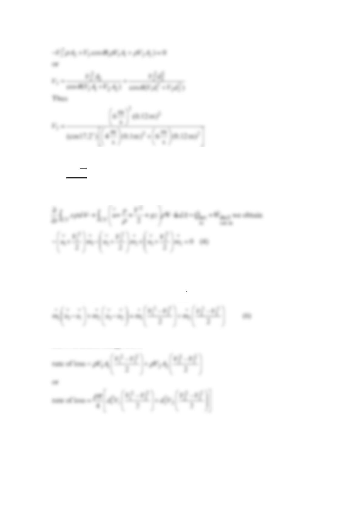
Now, combining Eqs. (1) and (3), we get
=
3
and
m
4.29 s
V
To determine the loss of available energy associated with the flow through this control
volume by applying the energy equation
Also, the conservation of mass equation, Eq. (3), can also be written as
−− + =
123
0mm m
(5)
Combining Eqs. (4) and (5), and assuming =0Q, we obtain
The left-hand side of Eq. (6) represents the rate of available energy loss in this fluid. Thus
rate of available energy loss is
Thus
−
22
2
mm
44.29
mss
Problem 5.129
Water flows vertically upward in a circular cross-sectional pipe. At section (1), the velocity
profile over the cross-sectional area is uniform. At section (2), the velocity profile is
17
c
Rr
wR
−
=
VK
where V= local velocity vector, c
w = centerline velocity in the axial direction, R= pipe
inside radius, and r= radius from pipe axis. Develop an expression for the loss in available
energy between sections (1) and (2).
Solution 5.129
From conservation of mass ==
12
12
QAV AV
, we have
=
12
VV
11.0
Since the velocity profile at section (1) is uniform. At section (2), we solve
Section (2)
Problem 5.130
Calculate the kinetic energy correction factor for each of the following velocity profiles for
a circular pipe:
(a)
=−
max 1r
uu R;
Solution 5.130
The kinetic energy correction factor (called the kinetic energy coefficient in the text) is
For incompressible flow in a circular pipe, this can be simplified to
The velocity profiles of part (a) and part (c), both fit the general format
=−
1
max 1n
r
uu R.
We shall first find
α
in terms of n.
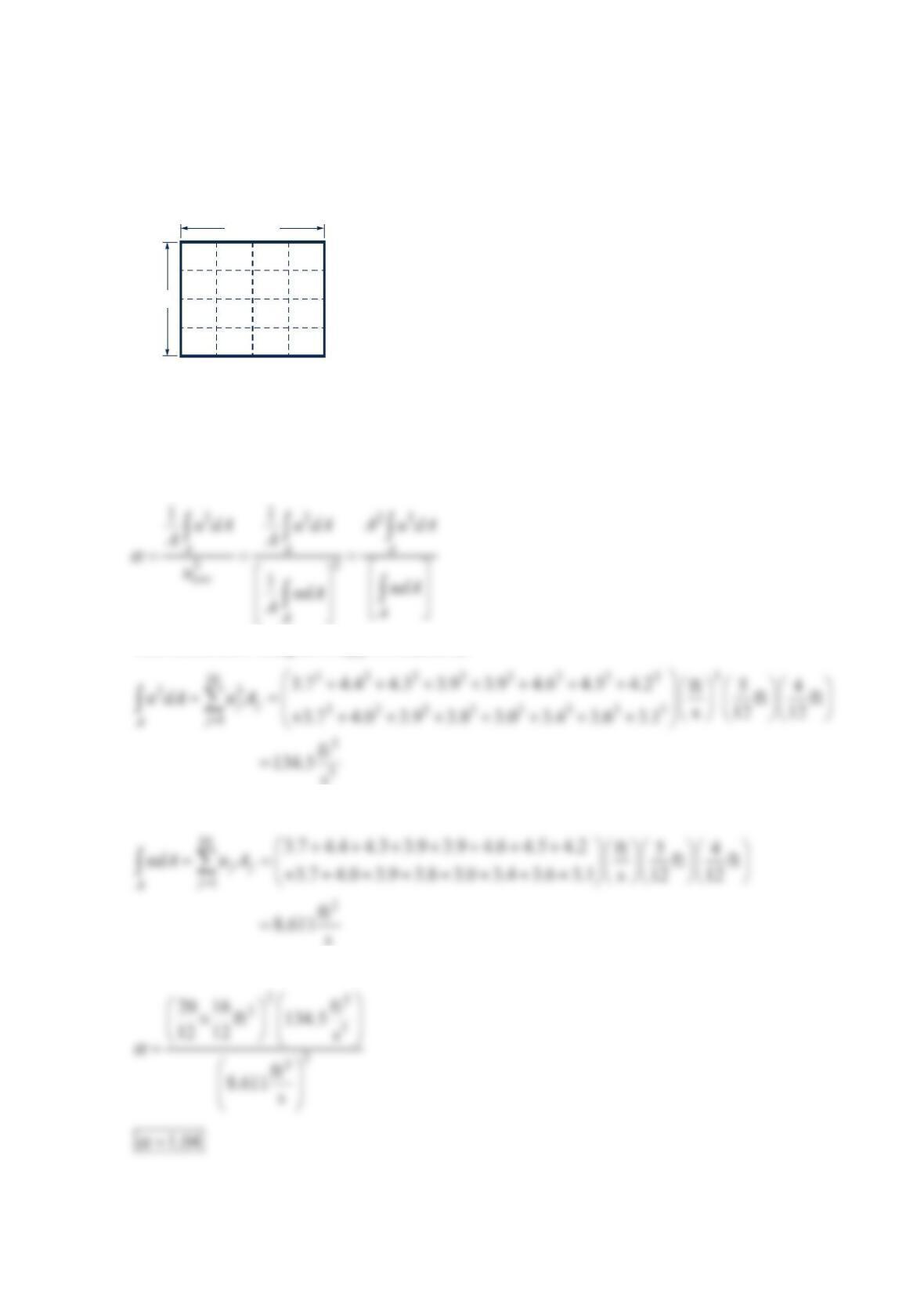
Problem 5.131
The cross-sectional area of a rectangular duct is divided into 16 equal rectangular areas, as
shown in the figure below. The axial fluid velocity measured in feet per second in each
smaller area is shown. Estimate the kinetic energy correction factor.
Solution 5.131
The kinetic energy correction factor is
The numerator integral is approximated as
The denominator integral is approximated as
Then
3.0 3.4 3.6
20.0 in.
Velocities in ft/s
16.0 in.
3.1
3.7 4.0 3.9 3.8
3.9 4.6 4.5 4.2
3.7 4.4 4.3 3.9
Problem 5.132
A small fan moves air at a mass flowrate of 0.004 lbm/s . Upstream of the fan, the pipe
diameter is 2.5 in. , the flow is laminar, the velocity distribution is parabolic, and the kinetic
energy coefficient, 1
α
, is equal to 2.0. Downstream of the fan, the pipe diameter is 1in. , the
flow is turbulent, the velocity profile is quite flat, and the kinetic energy coefficient, 2
α
, is
equal to 1.08. If the rise in static pressure across the fan is 0.015 psi and the fan shaft draws
0.00024 hp, compare the value of loss calculated: (a) assuming uniform velocity
distributions, (b) considering actual velocity distributions.
Solution 5.132
(a) For uniform velocity distributions upstream of the fan, the equation
We obtain the shaft work, shaft
net in
w from the given shaft power, shaft
net in
W, with
For and
in out
V
V, we use the equation
ρ
=mAV
. Thus,
Now from Eq. (1), we obtain
−
− −
=+
⋅
×
⋅
+
222
2
32
3
in. ft ft
( 0.015psi) 144 1.53 9.57
ft lb 1
ss
loss 1 ft
2
slug lbm lbm
slug
2.38 10 32.2 32.2
s
slug slug
ft
ft lb
33 lbm
or
Problem 5.133
Air enters a radial blower with zero angular momentum. It leaves with an absolute
tangential velocity, , of 200 ft/s
V
θ
. The rotor blade speed at rotor exit is
1
70 ft/s. If the
stagnation pressure rise across the rotor is 0.4 psi , calculate the loss of available energy
across the rotor and the rotor efficiency.
Solution 5.133
To determine the loss of available energy across the rotor we use the energy equation
Thus,
shaft out out
net in
wUV
θ
= (2)
Combining Eqs. (1) and (2) leads to
Then we calculate rotor efficiency from
Problem 5.134
Water enters a pump impeller radially. It leaves the impeller with a tangential component of
absolute velocity of 10 m/s . The impeller exit diameter is 60 mm , and the impeller speed is
1800 rpm . If the stagnation pressure rise across the impeller is 45kPa , determine the loss of
available energy across the impeller and the hydraulic efficiency of the pump.
Solution 5.134
The equation
ρ
−= − + −+
22
21
12 21
2.0 1.0 ()loss
22
ww
pp gzz is applicable to solving this
problem. Using the equation above, we obtain
Thus,
θ
ρ
η
=
2,2
(actual total pressure rise across impeller)
UV
or
Problem 5.135
Water enters an axial-flow turbine rotor with an absolute velocity tangential component,
V
θ
, of 15 ft/s . The corresponding blade velocity, U, is 50ft/s . The water leaves the rotor
blade row with no angular momentum. If the stagnation pressure drop across the turbine is
1
2psi, determine the hydraulic efficiency of the turbine
Solution 5.135
To determine the efficiency of the turbine, we use
,
shaft shaft in in
net out net in
wwUV
θ
=− = (2)
To determine the loss of available energy across the rotor, we use the energy equation
Combining Eqs. (1), (2), and (4), we obtain
and
Problem 5.136
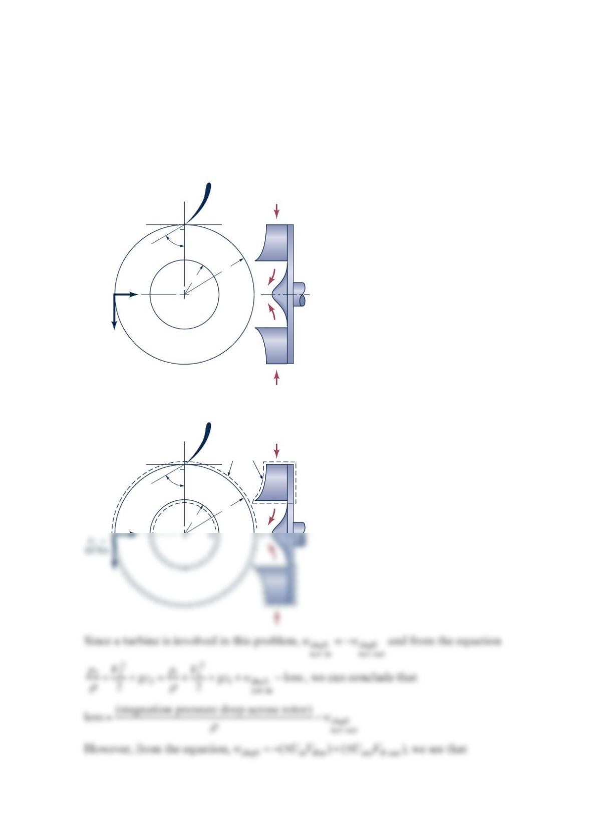
An inward flow radial turbine (see the figure below) involves a nozzle angle, 1
α
, of 60° and
an inlet rotor tip speed, 1
U
, of 30ft/s . The ratio of rotor inlet to outlet diameters is
2
.0. The
radial component of velocity remains constant at 20 ft/s through the rotor, and the flow
leaving the rotor at section (2) is without angular momentum. If the flowing fluid is water
and the stagnation pressure drop across the rotor is 16 psi , determine the loss of available
energy across the rotor and the hydraulic efficiency involved.
Solution 5.136
U
1
=
30 ft/s
V
r1
=
20 ft/s
60°
12
r
1
r
2
V
R1
=
20 ft/s
Fixed
control
volume
60°
r
1
r
2
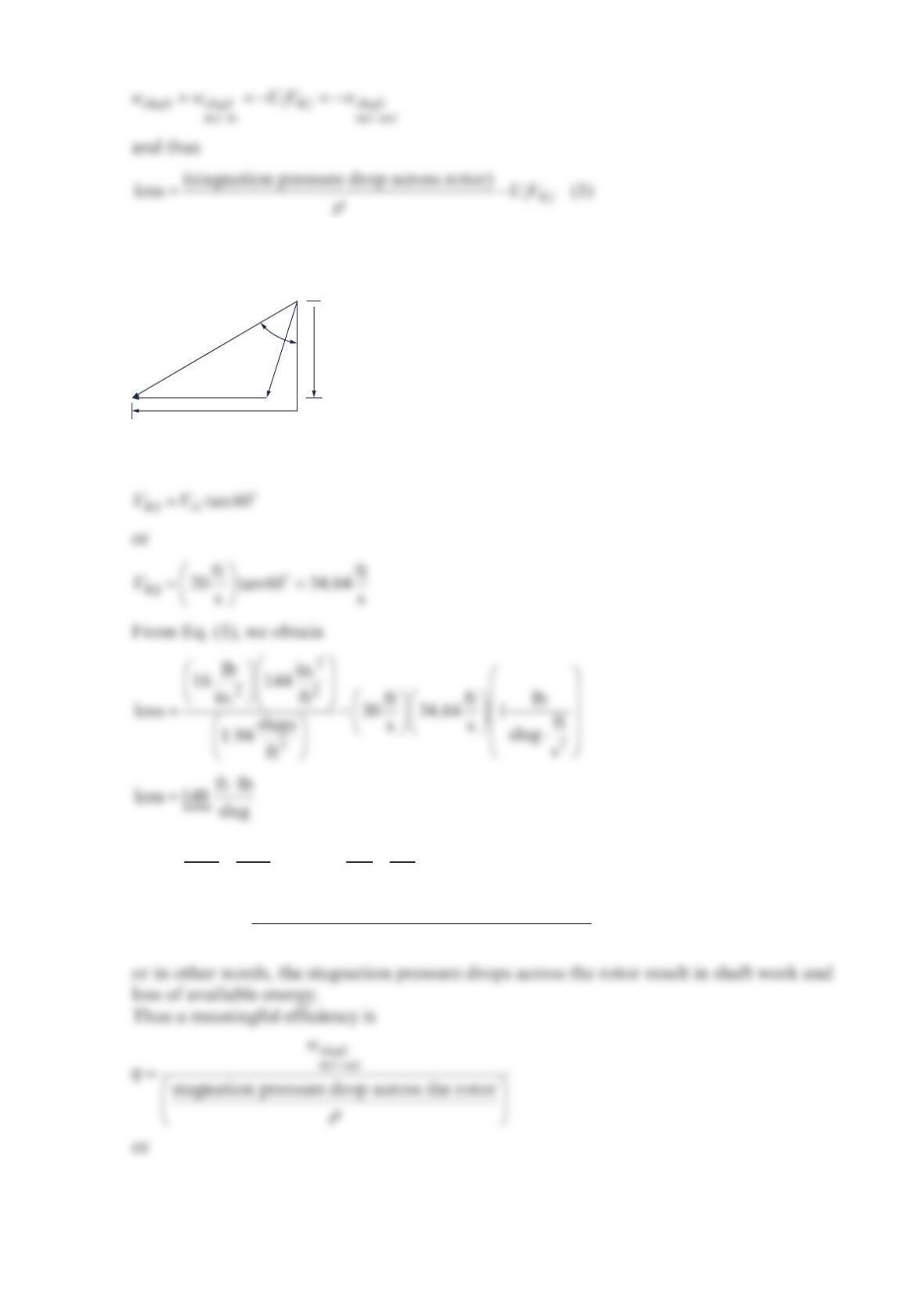
To determine the value of
θ
,1
V, we examine the velocity triangle for the flow entering the
rotor that is sketched below.
From the velocity triangle, we obtain
From
ρρ
++ =+++ −
22
out out in in
out in shaft
net in
loss
22
pV pV
gz gz w , we can conclude that
(stagnation pressure drop across the rotor)
loss
shaft
net out
w
ρ
+=
U
1
V
1
Vr
1
V
θ
,1
W
1
60°

⋅
2
ft ft lb
30 34.64 1 ft
ss
slug s0.875