Problem 5.119
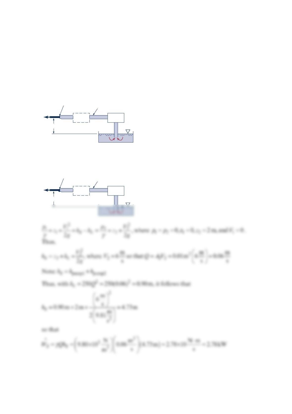
Water is to be pumped from the large tank shown in the figure below with an exit velocity
of 6 m/s. It was determined that the original pump (pump 1) that supplies 1kW of power to
the water did not produce the desired velocity. Hence, it is proposed that an additional
pump (pump 2) be installed as indicated to increase the flowrate to the desired value. How
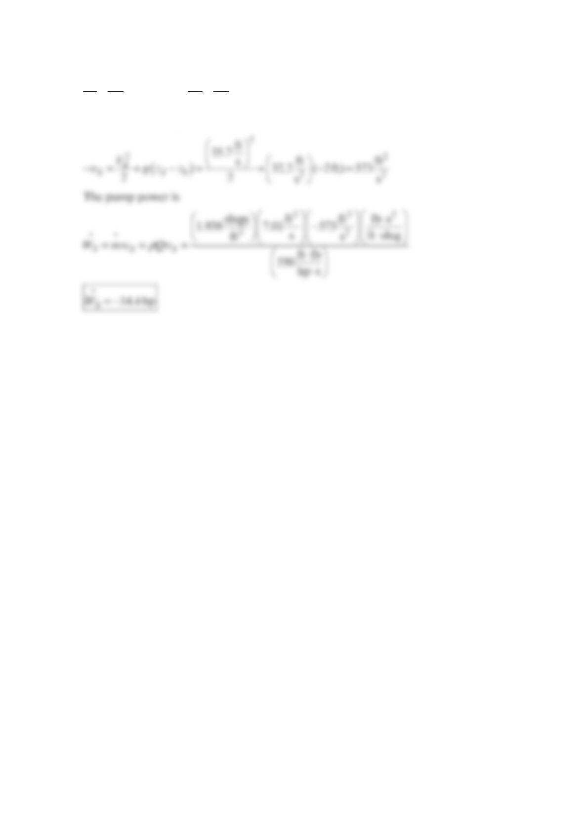
much power must pump 2 add to the water? The head loss for this flow is =2
L250hQ
,
where L
h is in m when Q is in 3
m/s.
Solution 5.119
V
= 6 m/s
Pump
#2
Pipe area = 0.02 m
2
Nozzle area = 0.01 m
2
2 m
Pump
#1
V
= 6 m/s
Pump
#2
Pipe area = 0.02 m
2
(2)
Nozzle area = 0.01 m
2
2 m
Pump
#1

Therefore,
Problem 5.120
Curtain of air An air curtain is produced by blowing air through a long rectangular nozzle
to produce a high-velocity sheet of air, or a “curtain of air.” This air curtain is typically
directed over a doorway or opening as a replacement for a conventional door. The air
curtain can be used for such things as keeping warm air from infiltrating dedicated cold
spaces, preventing dust and other contaminants from entering a clean environment, and
even just keeping insects out of the workplace, still allowing people to enter or exit. A
disadvantage over conventional doors is the added power requirements to operate the air
curtain, although the advantages can outweigh the disadvantage for various industrial
applications. New applications for current air curtain designs continue to be developed. For
example, the use of air curtains as a means of road tunnel fire security is currently being
investigated. In such an application, the air curtain would act to isolate a portion of the
tunnel where fire has broken out and not allow smoke and fumes to infiltrate the entire
tunnel system. (See Problem 5.120.)
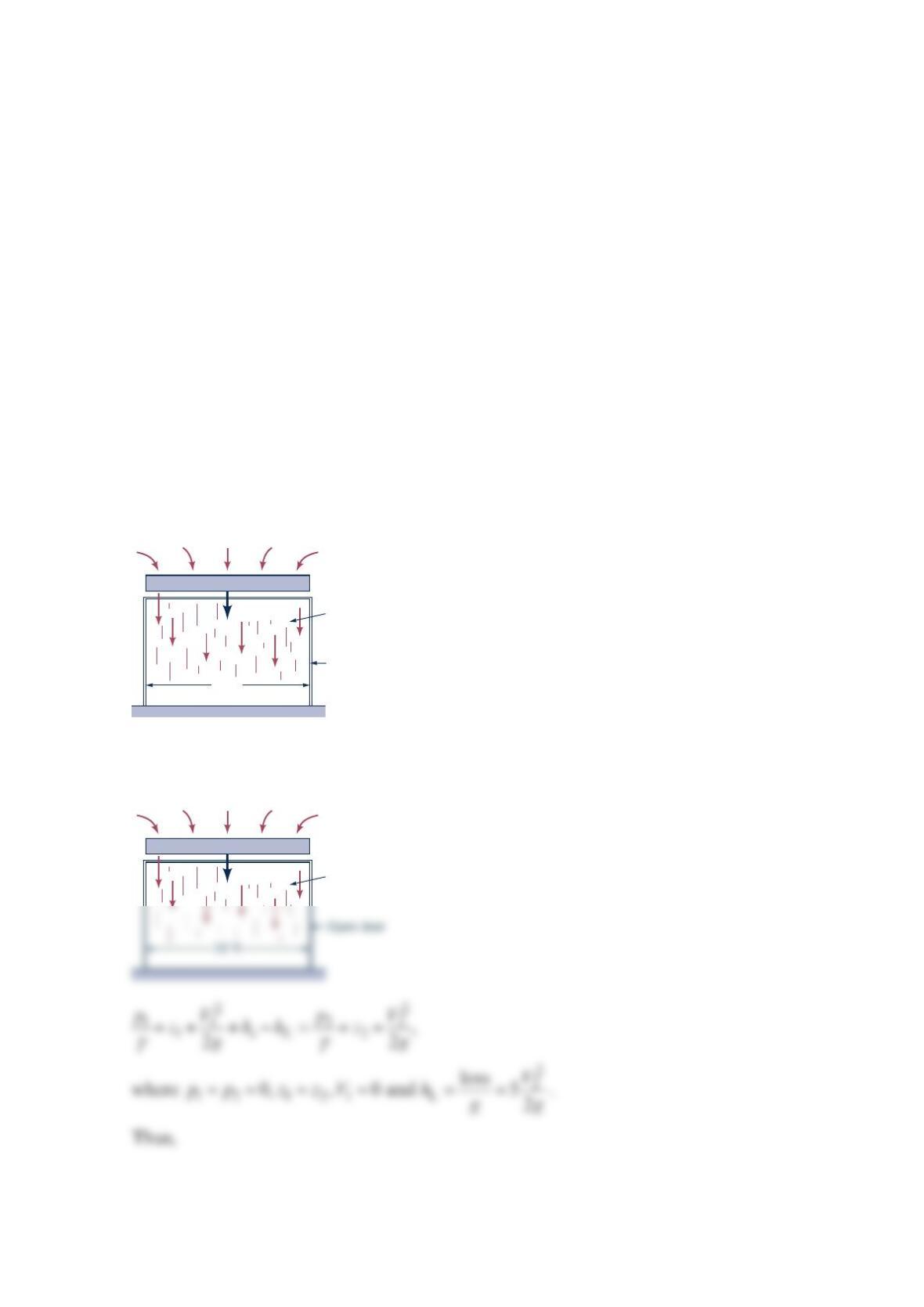
The fan shown in the figure below produces an air curtain to separate a loading dock from
a cold storage room. The air curtain is a jet of air 10 ft wide, 0.5ft thick moving with speed
= 30 ft/sV. The loss associated with this flow is 2
loss / 2
L
KV=, where 5
L
K
=. How much
power must the fan supply to the air to produce this flow?
Solution 5.120
Air curtain
(0.5-ft thickness)
Open door
10 ft
V
= 30 ft/s
Fan
Air curtain
(0.5-ft thickness)
V
= 30 ft/s
(1)
(2)
Fan
Hence,
Problem 5.121
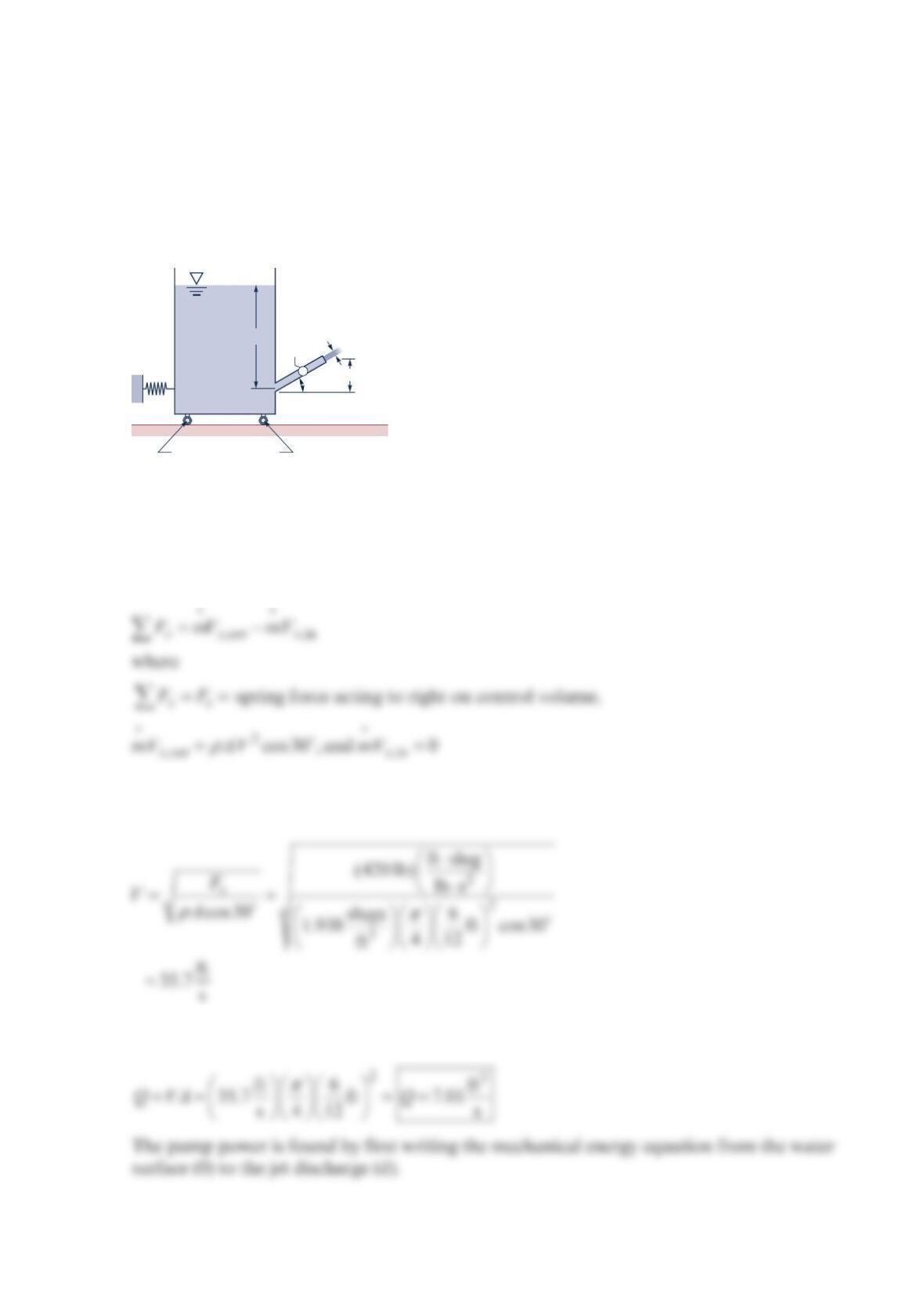
When the pump shown in the figure below is stopped, there is no flow through the system
and the spring force is zero. With the pump running, a
6
-in.-diameter jet leaves the pipe,
and the spring force is 420 lb . The water surface elevation in the tank is constant.
Determine the water flowrate and the power consumed by the pump. Assume quasi-steady
flow.
Solution 5.121
Write the linear momentum equation in the horizontal or x-direction for a control volume
enclosing the tank. Positive is to the right.
where V is the jet velocity leaving the discharge pipe and A is discharge pipe flow area.
Assuming 60 °F water,
The water flowrate is
30°1.0‘
3.0‘6-in. diameter
Jet
Pump
Spring
Frictionless rollers
For frictionless flow
22
00 dd
0d
22
S
pV pV
gz w gz
ρρ
++−=++
Now == ≈
0datm 0
and 0 to getppp V
Problem 5.122
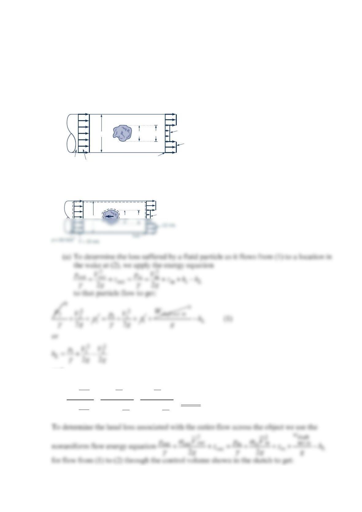
Air flows past an object in a pipe of 2-m diameter and exits as a free jet as shown in the
figure below. The velocity and pressure upstream are uniform at 10 m/s and 2
50 N/m ,
respectively. At the pipe exit, the velocity is nonuniform as indicated. The shear stress along
the pipe wall is negligible. (a) Determine the head loss associated with a particle as it flows
from the uniform velocity upstream of the object to a location in the wake at the exit plane
of the pipe. (b) Determine the force that the air exerts on the object.
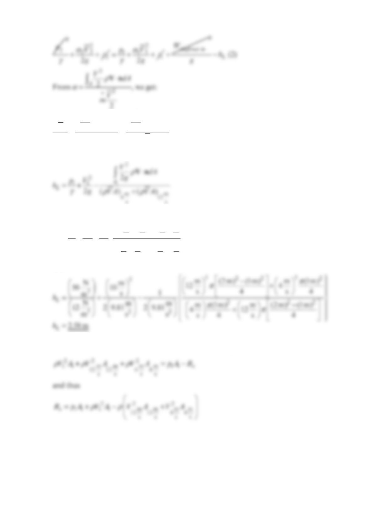
Solution 5.122
and
22
2
322
Nm m
50 10 ss
m8.45 m
Nmm
2 9.81 2 9.81
mss
L
h
4
=+ − =
12
2-m-dia. 1-m dia. 4 m/s
12 m/s
Exit
Wake
Air
p
= 50 N/m
2
V
= 10 m/s
Air
(1) (2)
R
x
ρρ
α
ρ
⋅⋅
==
22
2
•
22
2
VV
dA dA
Vgg
gVA
m
Vn Vn
Eq. (2) becomes
or
33
mm mm
212 12
ss ss
11
mm m m
ss s s
1
22
L
VA VA
pV
h
gg
VA V A
γ
33
4 4 12 12
+
=+ −
+
and
(b) To determine the force that the air puts on the object, x
R
, we use the horizontal
component of the linear momentum equation to get:
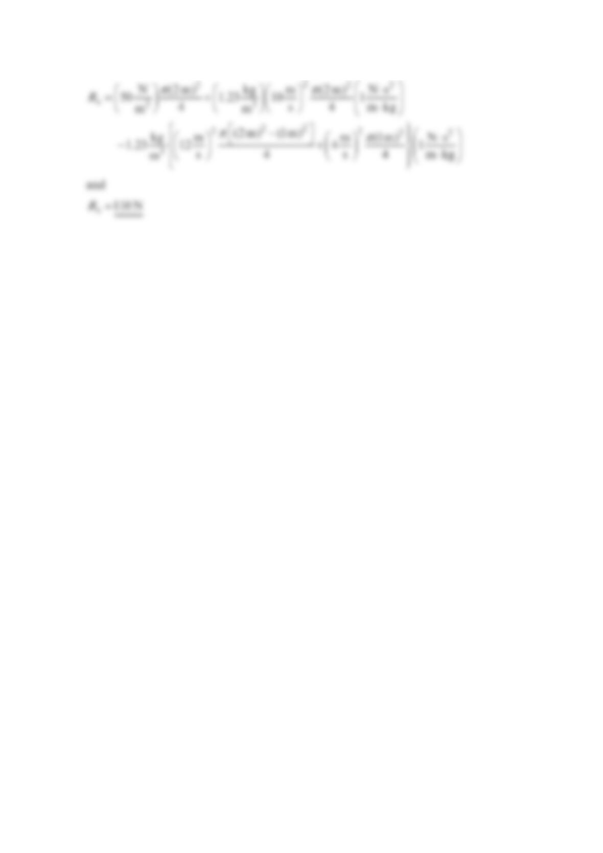
so
Problem 5.123
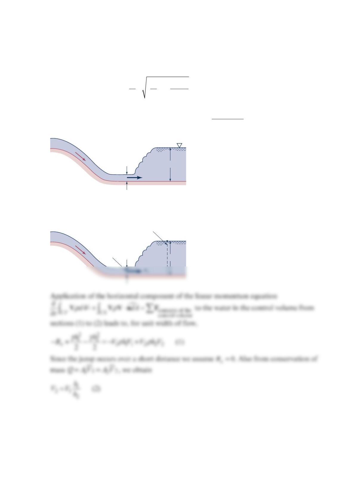
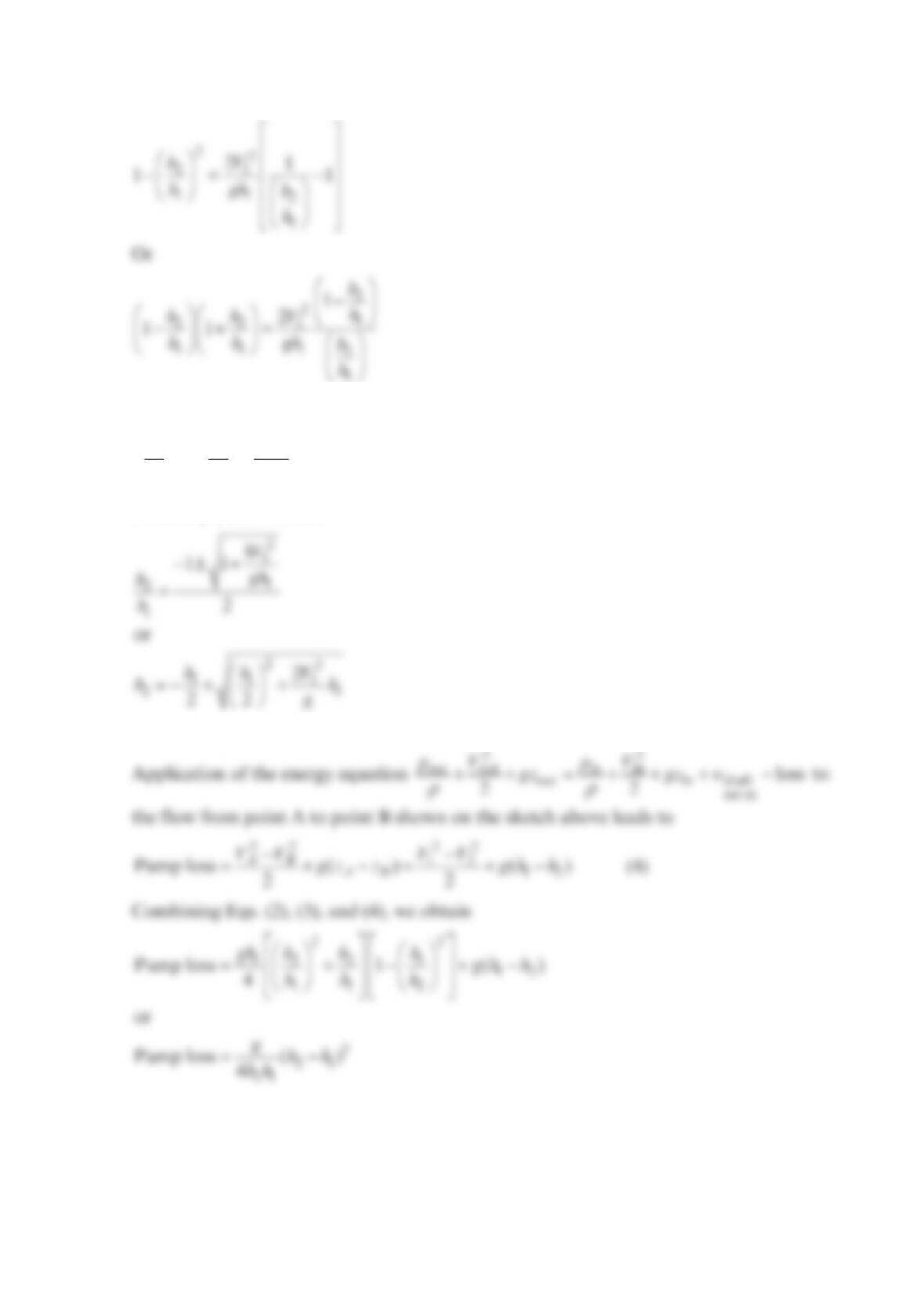
Near the downstream end of a river spillway, a hydraulic jump often forms, as illustrated in
the figure below. The velocity of the channel flow is reduced abruptly across the jump.
Using the conservation of mass and linear momentum principles, derive the following
expression for 2
h,
−+ +
22
11 11
2
2
= 22
hh Vh
hg
The loss of available energy across the jump can also be determined if energy conservation
is considered. Derive the loss expression −
=
12
3
21
()
jump loss 4
gh h
hh
Solution 5.123
V
1
h
1
h
2
B
h1h2
Section (1)
Section (2)
Combining Eqs. (1) and (2), we obtain
and
+−=
22
221
111
20
hhV
hhgh
(3)
From Eq. (3), we obtain
The other quadratic root is not meaningful.
Problem 5.124
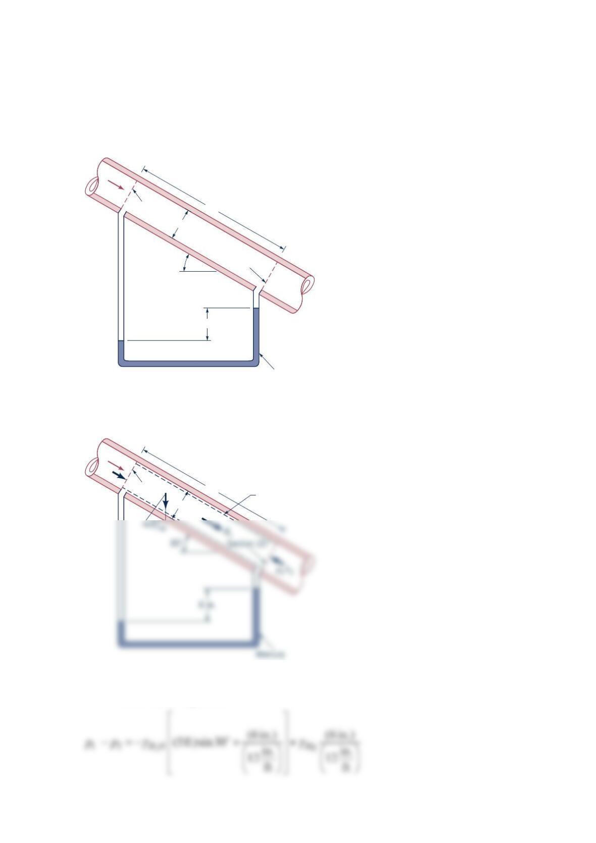
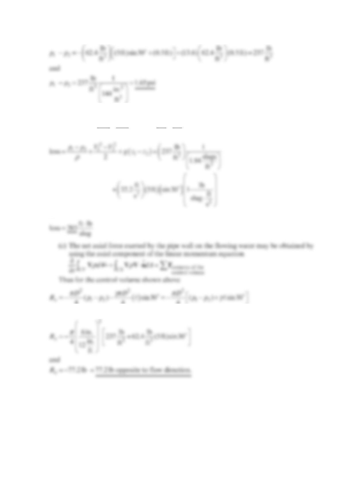
Water flows steadily down the inclined pipe as indicated in the figure below. Determine the
following: (a) the difference in pressure −
12
p
p, (b) the loss between sections (1) and (2),
(c) the net axial force exerted by the pipe wall on the flowing water between sections (1)
and (2).
Solution 5.124
(a) The difference in pressure, −
12
p
p, may be obtained from the manometer with the
fluid statics equation
5 ft
6 in.
30°
Mercury
Section (2)
Section (1)
Flow
6 in.
5 ft
=
ℓ
Control
volume
Section (1)
Flow
D
= 6 in.
p
1
A
1
W
or
(b) The loss per unit mass between sections (1) and (2) may be obtained with the
equation
ρρ
++ =++−
22
out out in in
out in loss
22
pV pV
gz gz Thus,
or
44 4
or
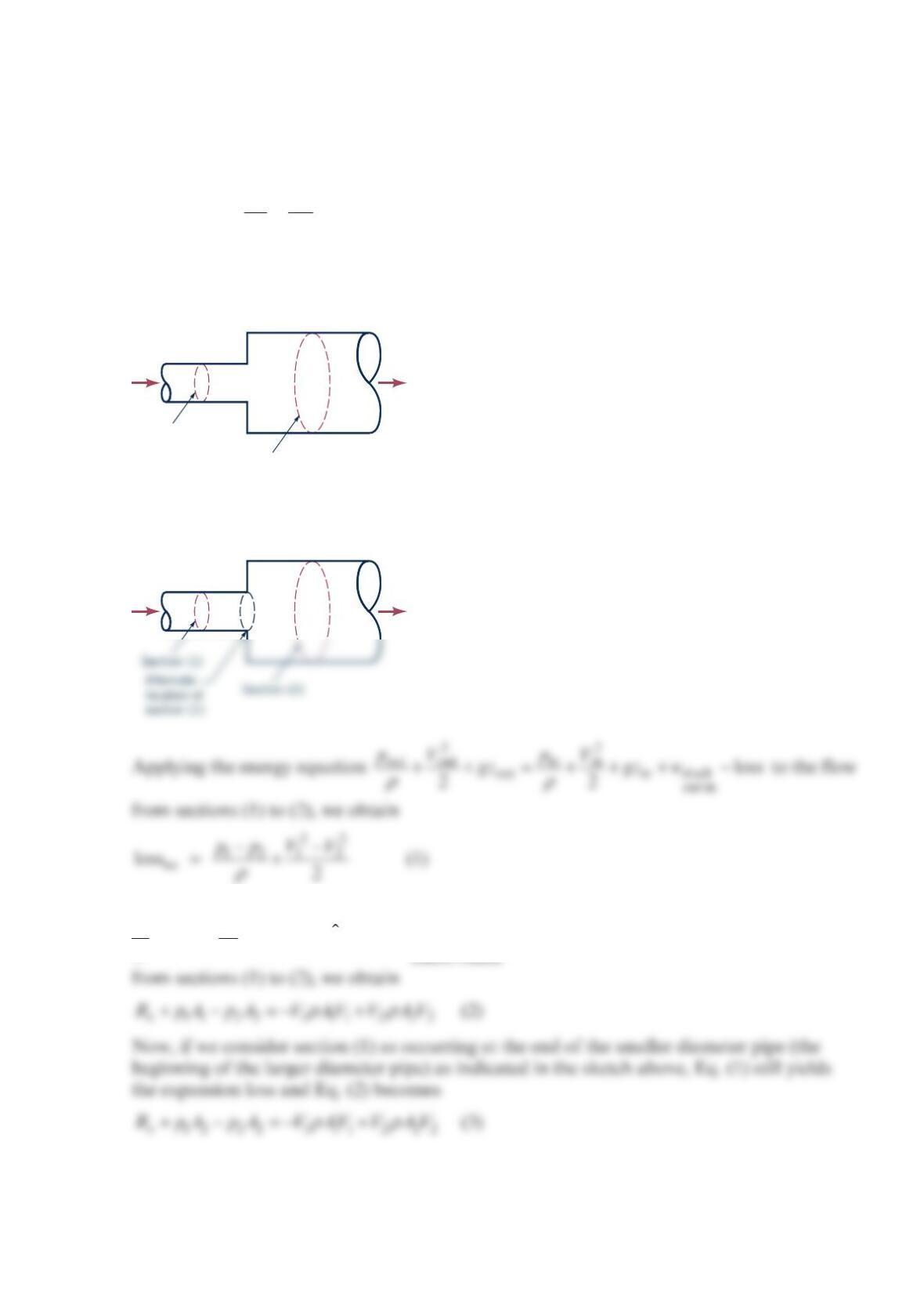
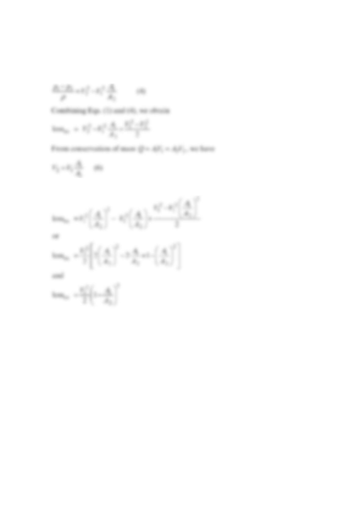
Problem 5.125
When fluid flows through an abrupt expansion as indicated in the figure below, the loss in
available energy across the expansion, ex
loss , can be expressed as
=−
22
11
ex
2
loss 1 2
AV
A
where 1
A= cross-sectional area upstream of expansion, 2
A= cross-sectional area
downstream of expansion, and 1
V = velocity of flow upstream of expansion. Derive this
relationship.
Solution 5.125
Applying the axial direction component of the linear momentum equation
dV
t
ρ
∂
∂
Vcontents of the
CV CS dA
ρ
+⋅=
VVn F to the fluid contained in the control volume
Section (1)
Section (2)
Note that with section (1) positioned at the end of the smaller diameter pipe, 1
p
acts over
area 2
A. Also, because of the jet flow from the smaller diameter pipe into the larger
diameter pipe, the value of x
R will be small enough compared to the other terms in Eq. (3)
that we can assume =0
x
R. Then from Eq. (3)
Combining Eqs. (5) and (6), we get
Problem 5.126
Water (60 °F) flows through an annular space formed by inserting a
1
-in.-radius solid
cylinder into a
1
.5-in.-radius tube. The following axial velocities were measured in the
annular space.
(r –
r
i)/(
r
0 –
r
i) u(ft/s)
0.1 12
0.2 23
0.3 28
0.4 33
0.5 34
0.6 31
0.7 28
0.8 21
0.9 10
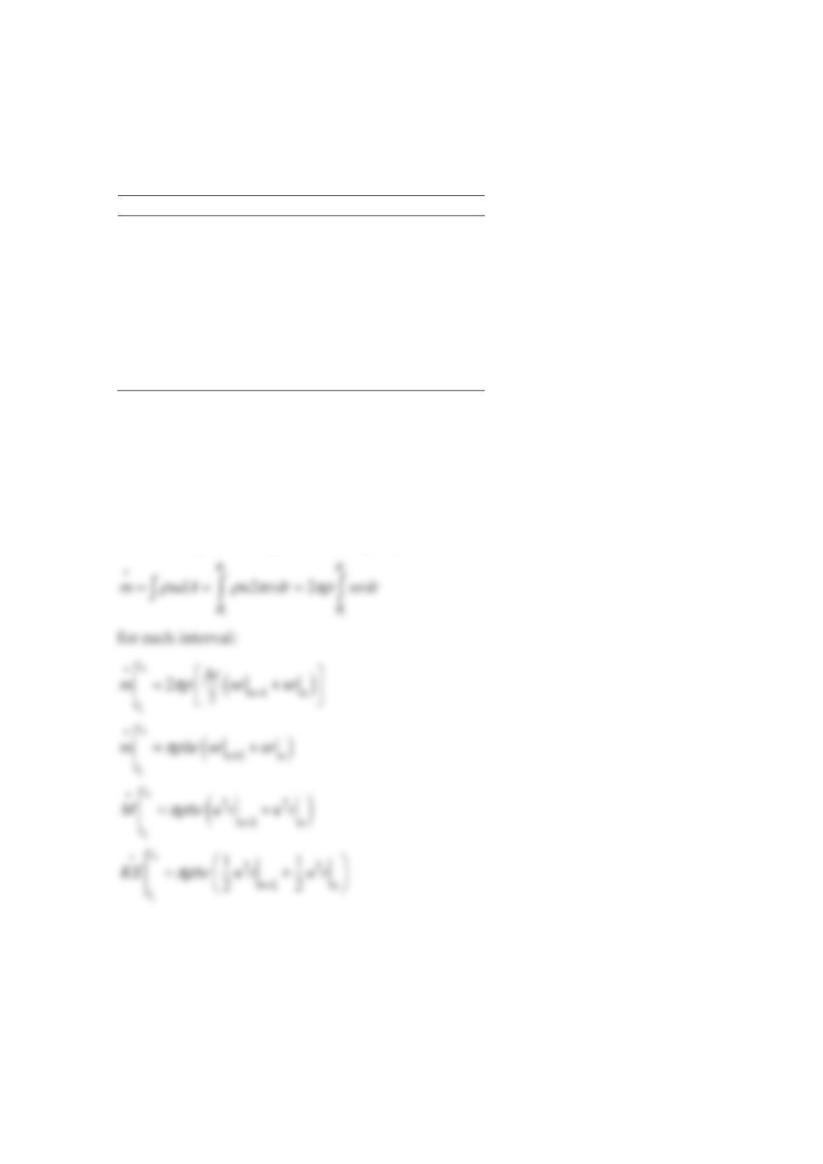
Assume that the no-slip condition ( =0u) exists at the solid boundaries. What are the rates
of mass, momentum, and kinetic energy flow through the annular space?
Solution 5.126
Perform required integrations using trapezoidal rule.
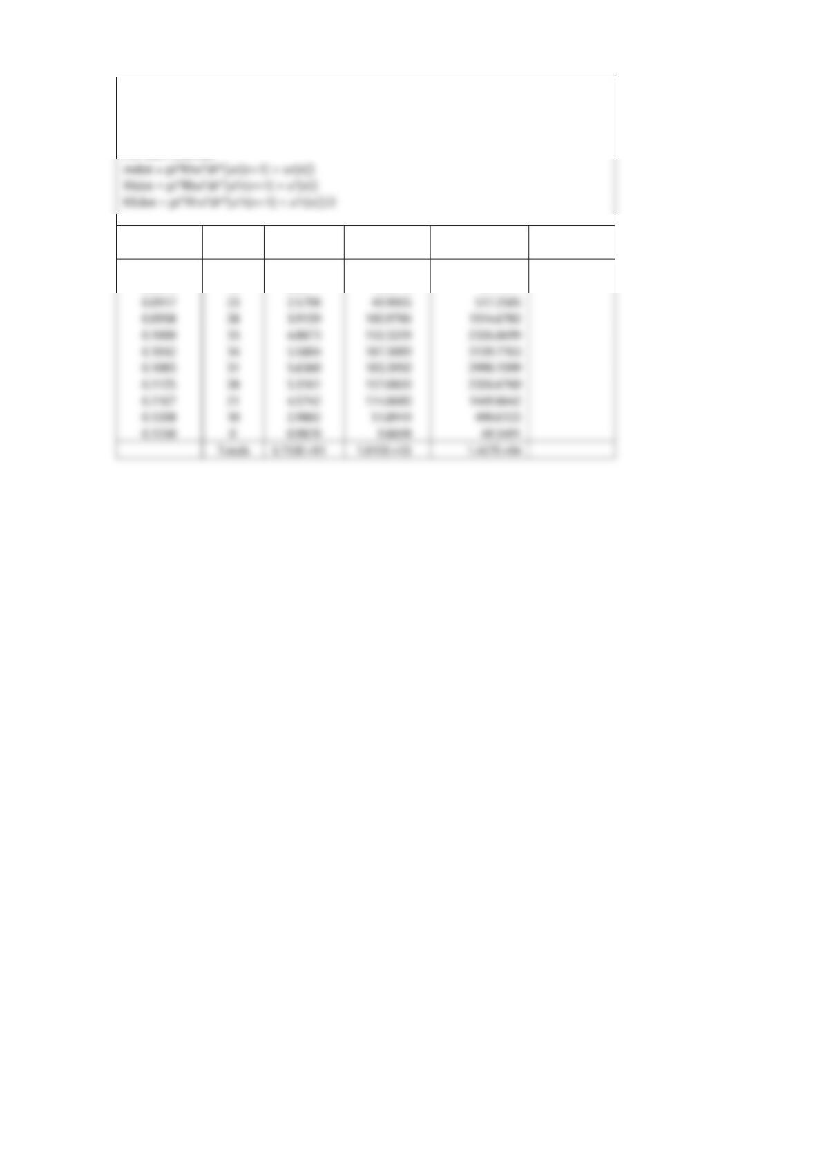
Ri = 1 in. Rho= 62.4 lbm/ft3
Ro = 1.5 in. pi= 3.14159
dr = 0.004167 ft
For each interval:
r (ft) u (ft/s)
mdot
(lbm/s)
Mdot
(ft-lbm/s2)
KEdot
(ft2-lbm/s3)
0.0833 0
0.0875 12 0.8577 10.2918 61.7511