Problem 5.59
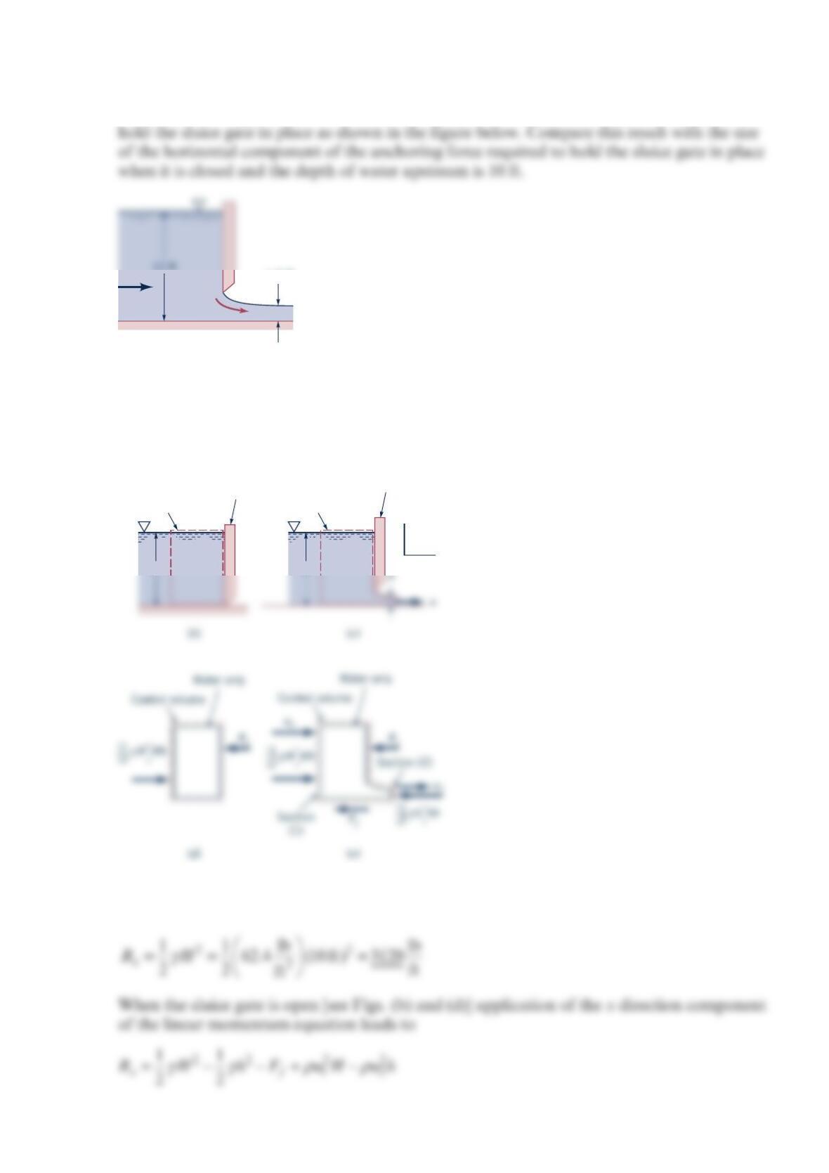
Determine the magnitude of the horizontal component of the anchoring force required to
Solution 5.59
The control volumes of the figures below are appropriate for use in solving this problem.
When the sluice gate is closed [see Figs. (a) and (c)] application of the x direction
component of the linear momentum equation leads to
4 ft/s
1.5 ft
H
Control volume
Closed sluice
gate
H
Control volume
Open sluice
gate
x
z
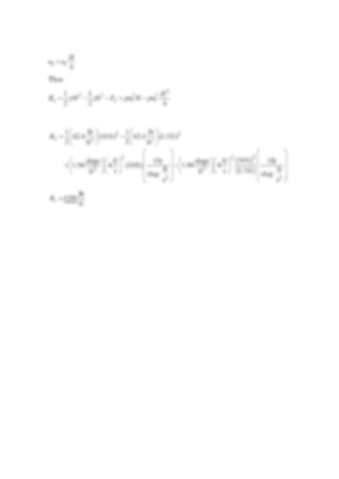
The exit velocity 2
u may be expressed in terms of the inlet velocity u, with the conservation
of mass equation as follows
Assuming
f
F
is negligibly small, we obtain
Thus it takes considerably less force to hold the sluice gate in place when it is opened as
compared to when it is closed.
Problem 5.60
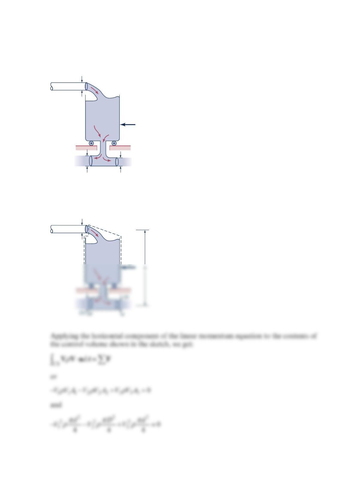
Water flows steadily into and out of a tank that sits on frictionless wheels as shown in the
figure below. Determine the diameter
D
so that the tank remains motionless if 0
F
=.
Solution 5.60
F
d
Dd
d
(1)
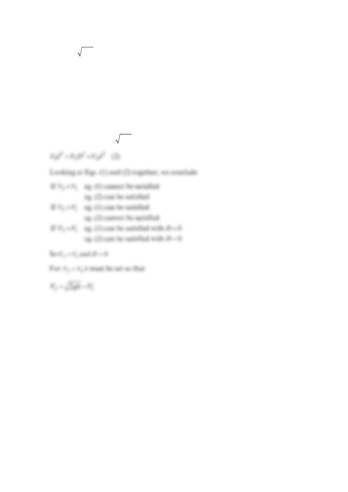
Since
23 2VV gh== , we obtain
=−
22 22 2
133
Vd Vd VD (1)
From the conservation of mass equation, we get
=+
=+
133
222
12 3
or
QQQ
Vd V D Vd
Again, since 23 2VV gh== , we get
Problem 5.61
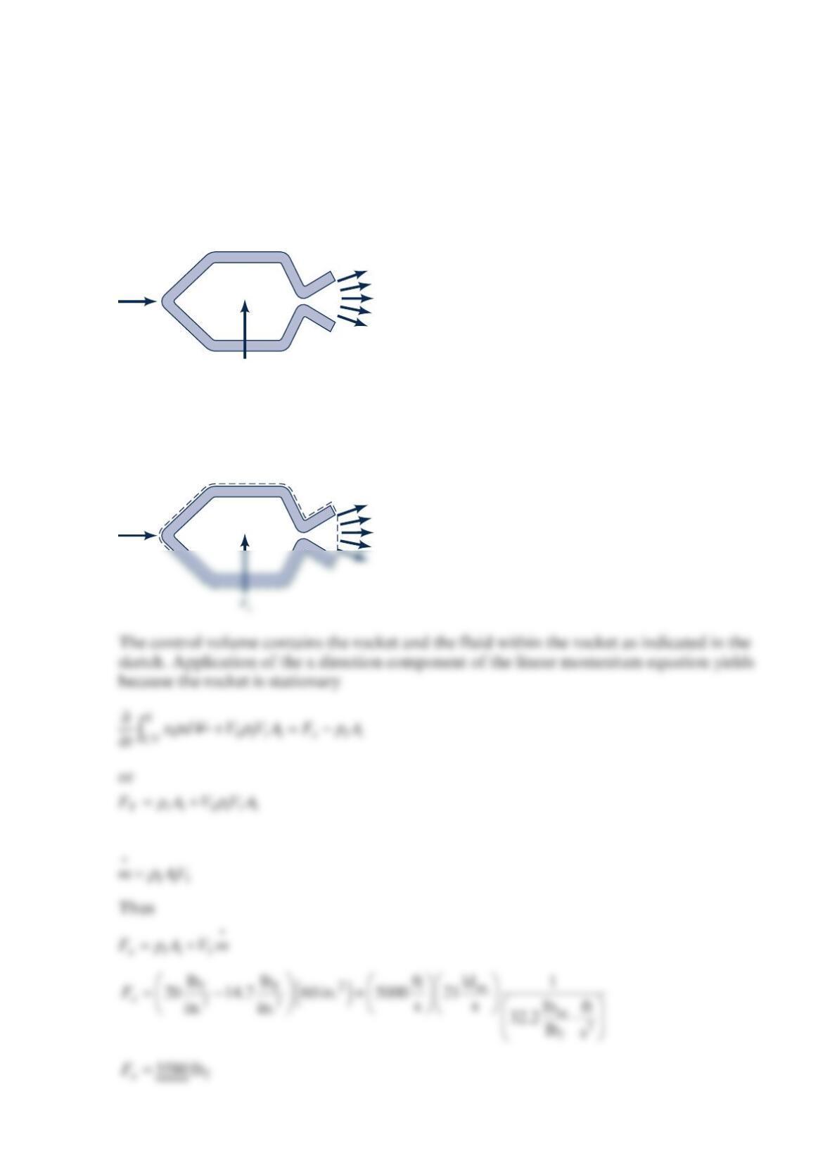
The rocket shown in the figure below is held stationary by the horizontal force, x
F
, and the
vertical force, z
F
. The velocity and pressure of the exhaust gas are 5000 ft/s and 20 psia at
the nozzle exit, which has a cross section area of 2
60 in. . The exhaust mass flowrate is
constant at 21lbm/s . Determine the value of the restraining force X
F
. Assume the exhaust
flow is essentially horizontal.
Solution 5.61
But
F
z
F
x
Fx
F
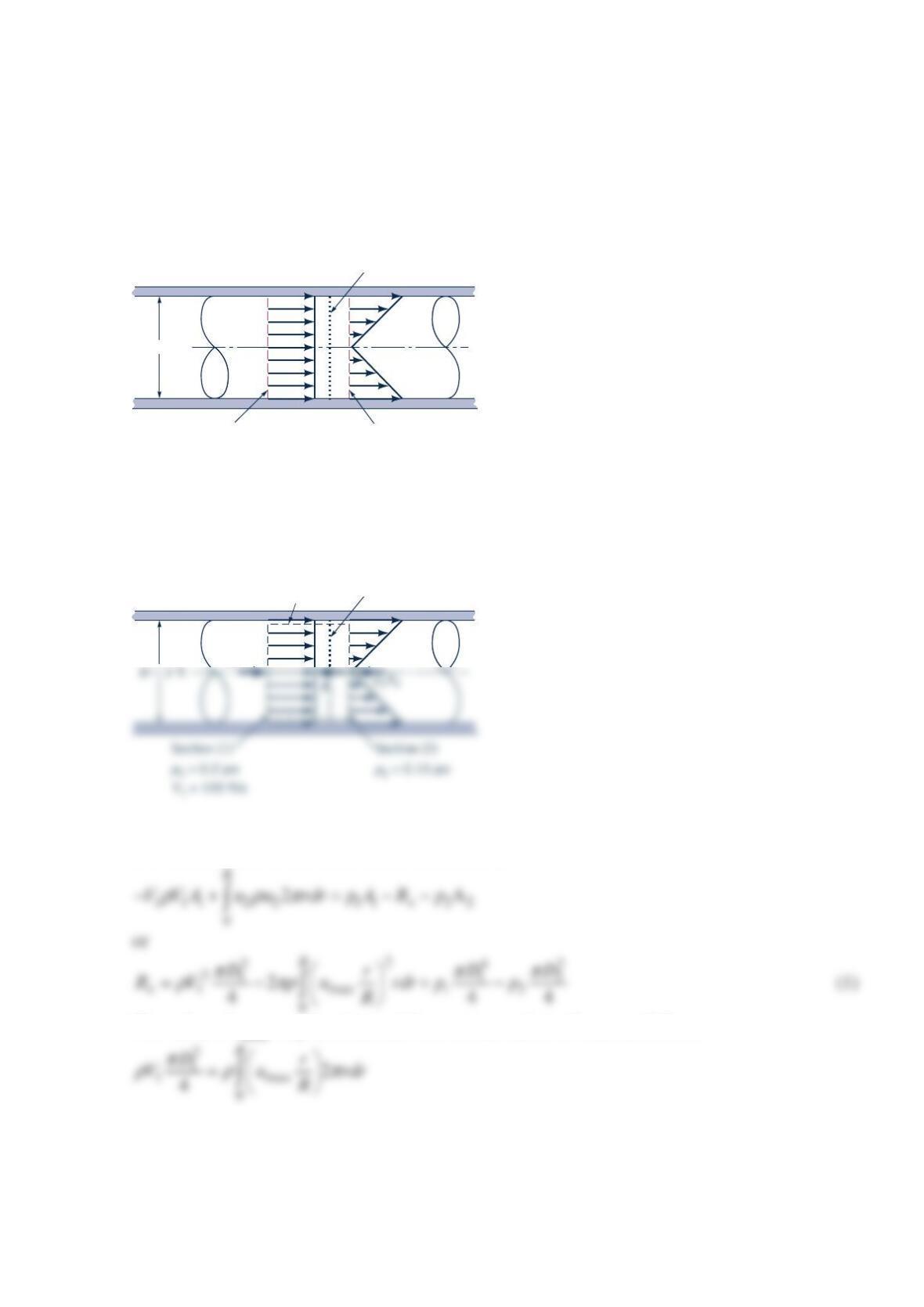
Problem 5.62
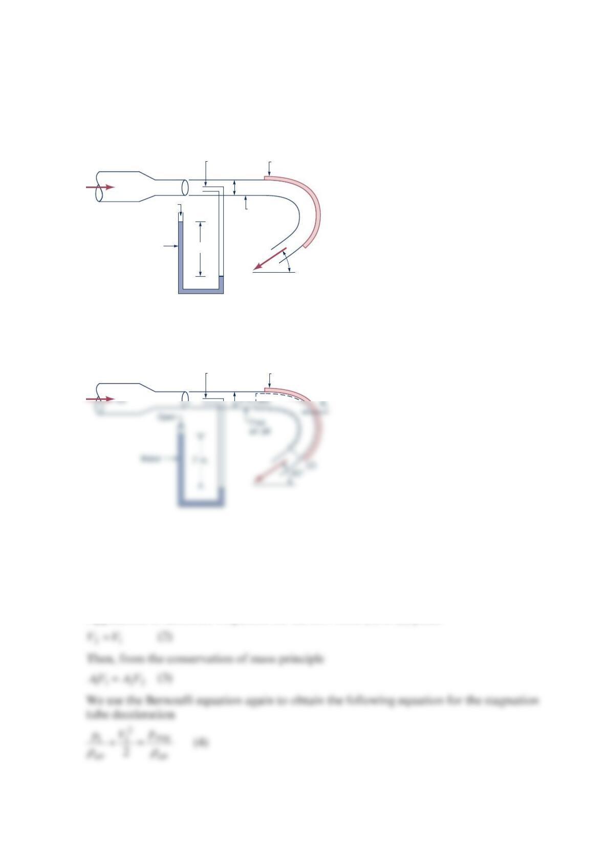
Air discharges from a 2-in.-diameter nozzle and strikes a curved vane, which is in a vertical
plane as shown in the figure below. A stagnation tube connected to a water U-tube
manometer is located in the free air jet. Determine the horizontal component of the force
that the air jet exerts on the vane. Neglect the weight of the air and all friction.
Solution 5.62
Note that we ignore the effect of atmospheric pressure on the value of x
R
in our solution
below and use gage pressures. The atmospheric pressure force may need consideration
when identifying reaction forces. For the air flowing through the control volume sketched
above, the x-direction component of the linear momentum equation is
1112 22
cos30
air air x
VVAV VA R
ρρ
−
−=−
(1)
Application of Bernoulli’s equation for the flow from (1) to (2) yields
7 in.
Fixed vane
2-in. dia.
Free
air jet
Stagnation
tube
Air
Water
Open
30°
Fixed vane
(1)
Stagnation
tube
For the manometer, we obtain with the equation of hydrostatics
or
=
and
2.96 lb
x
R
Problem 5.63
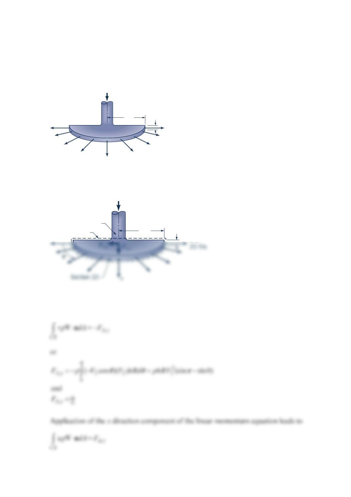
Water is sprayed radially outward over
1
80° as indicated in the figure below. The jet sheet is
in the horizontal plane. If the jet velocity at the nozzle exit is 20 ft/s , determine the direction
and magnitude of the resultant horizontal anchoring force required to hold the nozzle in
place.
Solution 5.63
The control volume includes the nozzle and water between sections (1) and (2) as indicated
in the sketch above. Application of the y direction component of the linear momentum
equation yields
8 in. 0.5 in.
V =
20 ft/s
8 in.
Section (1)
Control volume 0.5 in. = h
or
()() ()
π
8
,
ft
0.5 in. in. 20 2
slugs lb
s
Ax
Problem 5.64
A sheet of water of uniform thickness ( 0.01 m
h
=) flows from the device shown in the
figure below. The water enters vertically through the inlet pipe and exits horizontally with a
speed that varies linearly from 0to10m/s along the 0.2-mlength of the slit. Determine the y
component of anchoring force necessary to hold this device stationary.
Solution 5.64
A control volume that contains the box portion of the device and the water in the box as
shown in the sketch above is used. Application of the y-direction component of the linear
momentum equation yields
0.2 m
h = 0.01 m
x
y
0 m/s
10 m/s
Q
h = 0.01 m
Control
volume
FAy x
Q
Thus
Problem 5.65
The results of a wind tunnel test to determine the drag on a body (see the figure below) are
summarized below. The upstream [section (1)] velocity is uniform at 100 ft/s . The static
pressures are given by ==
12
14.7 psiapp . The downstream velocity distribution, which is
symmetrical about the centerline, is given by
100 30 1 3ft
3
100 3ft
y
uy
uy
=−− ≤
= >
where u is the velocity in
f
t/s and y is the distance on either side of the centerline in feet (see
the figure below). Assume that the body shape does not change in the direction normal to
the paper. Calculate the drag force (reaction force in x direction) exerted on the air by the
body per unit length normal to the plane of the sketch.
Solution 5.65
The control volume containing air only as shown in the figure is used. Application of the x
direction component of the linear momentum equation leads to
u
Body 3 ft
3 ft
V2
= 100 ft/s
V1
= 100 ft/s
Section (2)
Section (1)
u
Body
Streamline
V2
= 100 ft/s
V1
= 100 ft/s
To determine the distance
h
, the conservation of mass equation is applied between sections
(1) and (2) as follows
or
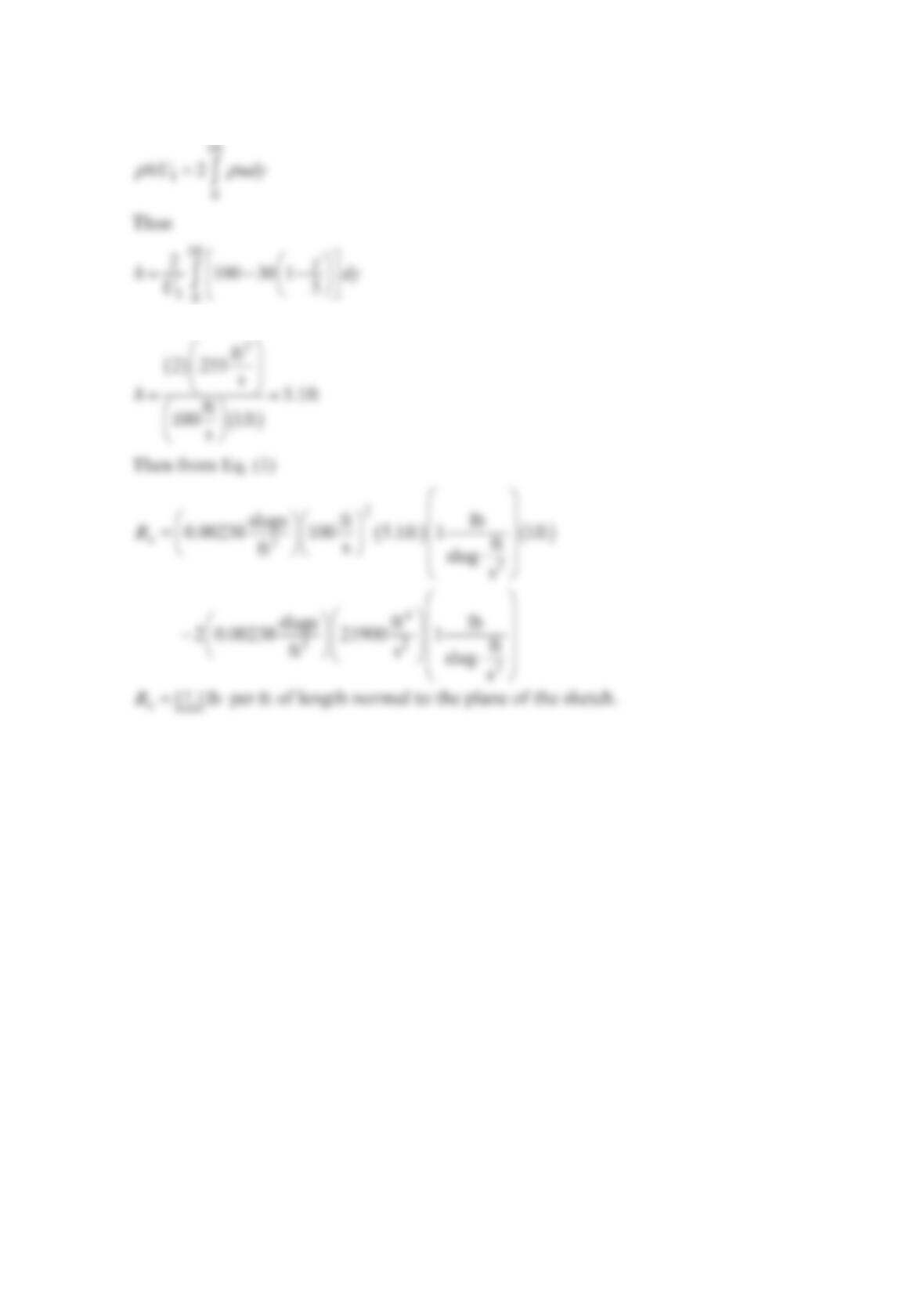
Problem 5.66
A variable mesh screen produces a linear and axisymmetric velocity profile as indicated in
the figure below in the airflow through a 2-ft-diameter circular cross-sectional duct. The
static pressures upstream and downstream of the screen are 0.2 and 0.15psi and are
uniformly distributed over the flow cross-sectional area. Neglecting the force exerted by the
duct wall on the flowing air, calculate the screen drag force.
Solution 5.66
Application of the axial component of the linear momentum equation to the flow through
the control volume shown in the sketch leads to
The value of max
u may be obtained from conservation of mass as follows
Variable mesh screen
Section (2)Section (1)
p
1
= 0.2 psi
V
1
= 100 ft/s
D
= 2 ft
p
2
= 0.15 psi
Variable mesh screenControl volume
p
A
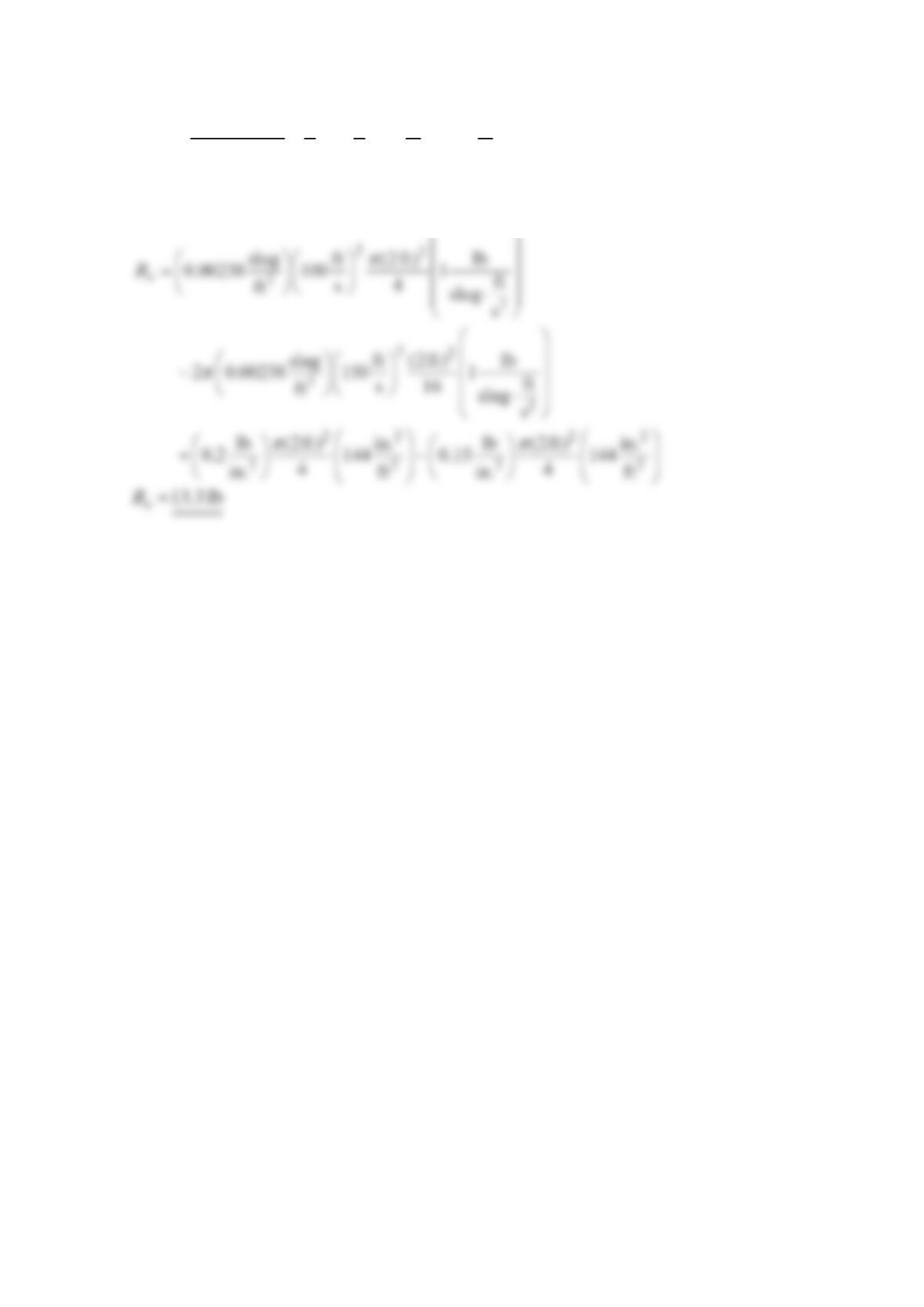
Thus
====
2
11
max 1
2
0
33 ft ft
100 150
22 s s
(2)(4)
R
VD R
uV
rdr
From Eq. (1)
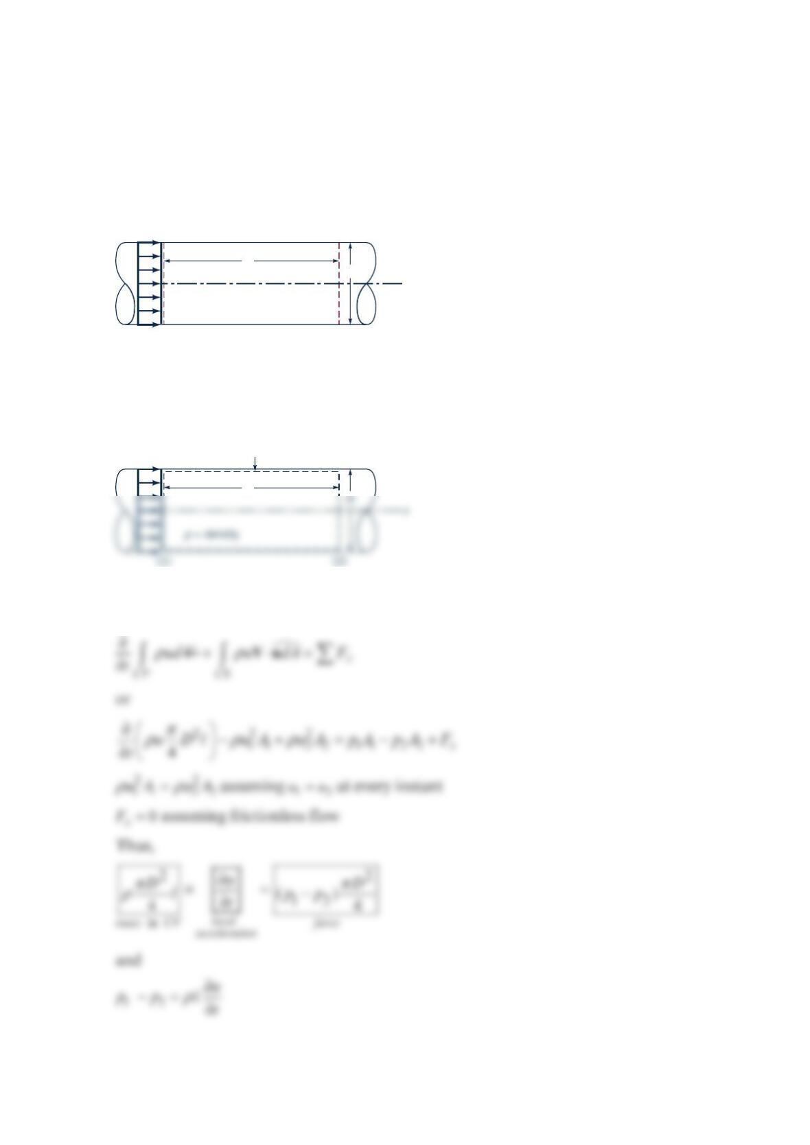
Problem 5.67
Consider unsteady flow in the constant diameter, horizontal pipe as shown in the figure
below. The velocity is uniform throughout the entire pipe, but it is a function of time:
()
=utVi
. Use the x component of the unsteady momentum equation to determine the
pressure difference −
12
p
p. Discuss how this result is related to =
xx
Fma
.
Solution 5.67
Using the control volume shown in the sketch and applying the x-component of the
unsteady linear momentum equation to the contents of this CV , we get
u
(
t
)
ℓ
D
x
(1) (2)
= density
ρ
u
(
t
)
ℓ
CV
Problem 5.68
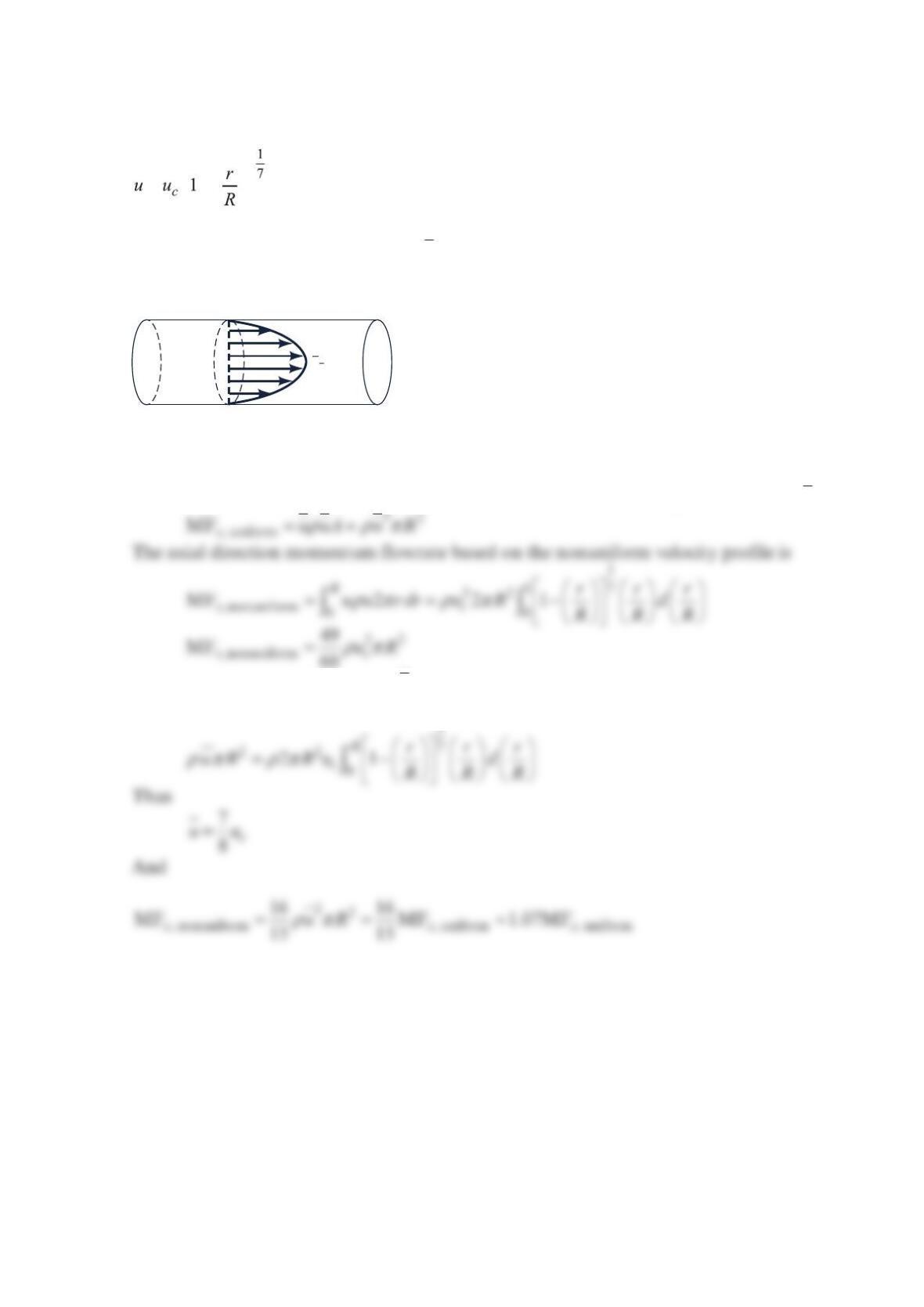
In a laminar pipe flow that is fully developed, the axial velocity profile is parabolic. That is,
=−
as is illustrated in the figure below. Compare the axial direction momentum flowrate
calculated with the average velocity, ,u with the axial direction momentum flowrate
calculated with the nonuniform velocity distribution taken into account.
Solution 5.68
The axial direction momentum flowrate based on a uniform velocity profile with =uu is
To obtain a relationship between u and c
u, we use the conservation of mass equation as
follows
u
u
c
Problem 5.70
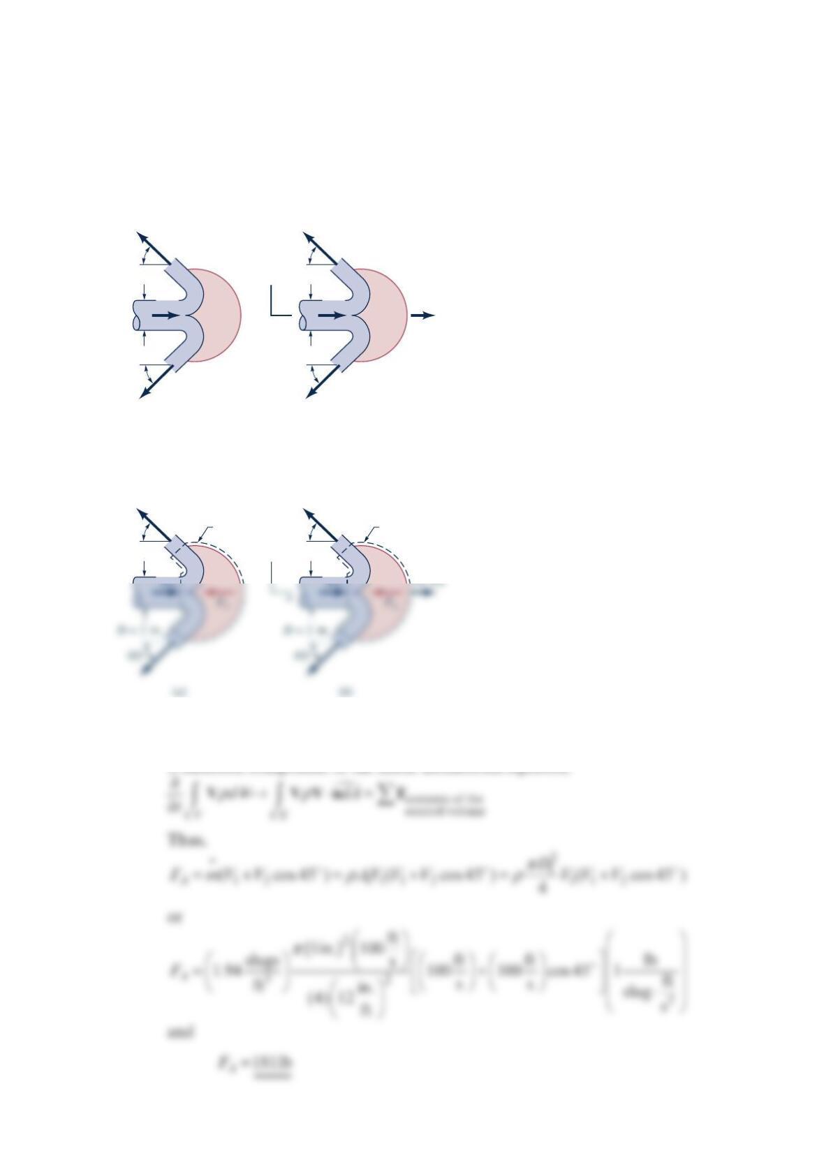
A Pelton wheel vane directs a horizontal, circular cross-sectional jet of water symmetrically
as indicated in the figure below. The jet leaves the nozzle with a velocity of 100 ft/s.
Determine the x-direction component of anchoring force required to (a) hold the vane
stationary, (b) confine the speed of the vane to a value of 10 ft/s to the right. The fluid speed
magnitude remains constant along the vane surface.
Solution 5.70
(a) To determine the x-direction component of anchoring force required to hold
the vane stationary, we use the stationary control volume shown above and the
x-direction component of the linear momentum equation
45°
45°
D
= 1 in.
100
ft/s
(
a
)
45°
45°
D
= 1 in.
100
ft/s 10 ft/s
(
b
)
y
x
45°
100
Control
volume
45°
100
y
Control
volume
(b) To determine the x-direction component of anchoring force requited to
confine the vane to a constant speed of 10 ft/s to the right, we use a control
volume moving to the right with a speed of 10 ft/s and the x-direction component
of the linear momentum equation for a translating control volume
contents of the
control volume
C
V
dA
ρ
⋅=
WWn F
Thus,
ssss
Thus, Eq. (1) leads to
=146 lb
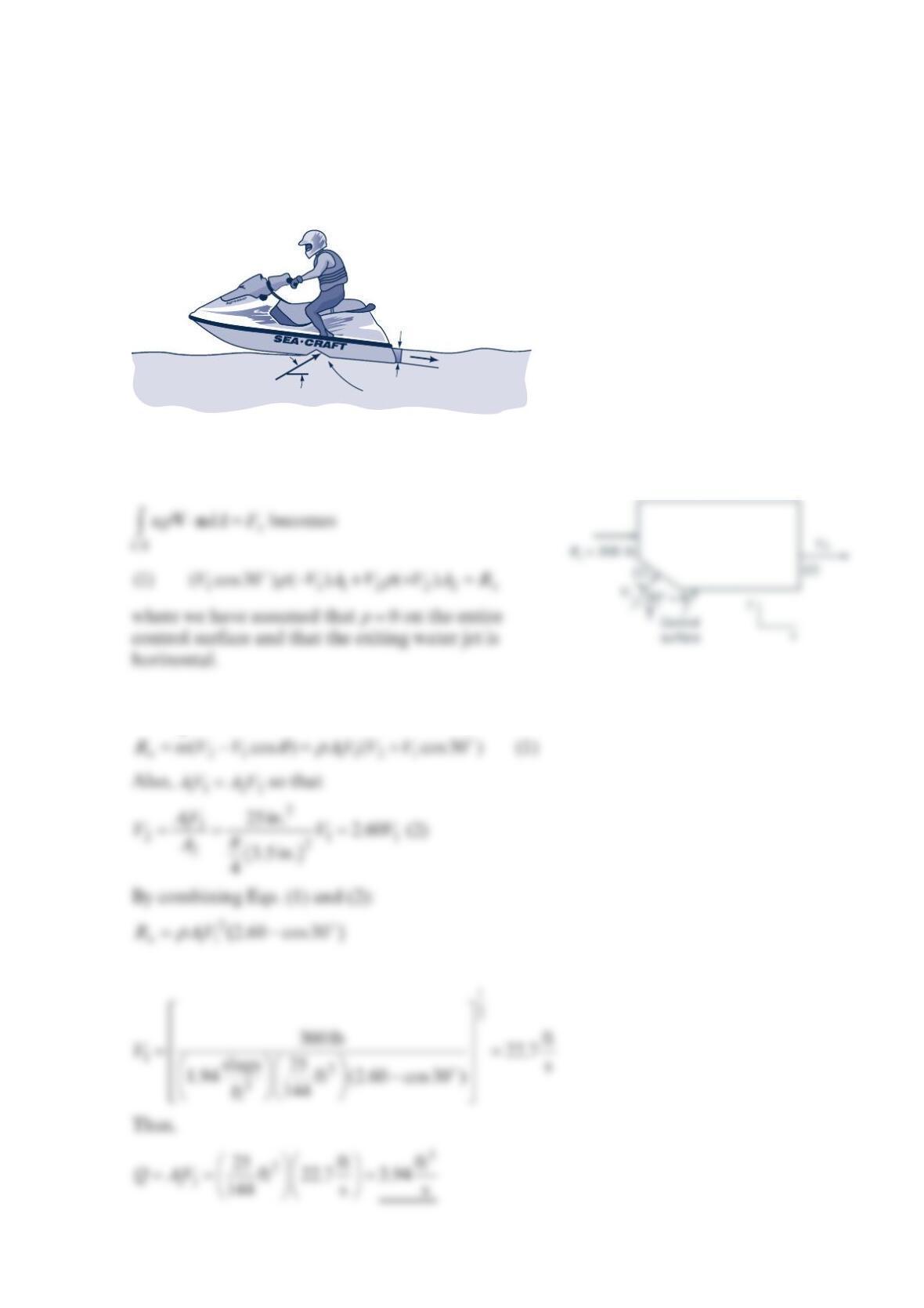
Problem 5.71
The thrust developed to propel the jet ski as shown in the figure below is a result of water
pumped through the vehicle and exiting as a high-speed water jet. For the conditions shown
in the figure, what flowrate is needed to produce a 300-lb thrust? Assume the inlet and
outlet jets of water are free jets.
Solution 5.71
For the control volume indicated the x-component of the momentum equation
With 11 2 2
mAV AV
ρρ
==
, Eq. (1) becomes
or
3.5-in.-diameter
outlet jet
30
°
25-in.
2
inlet area