Problem 5.97
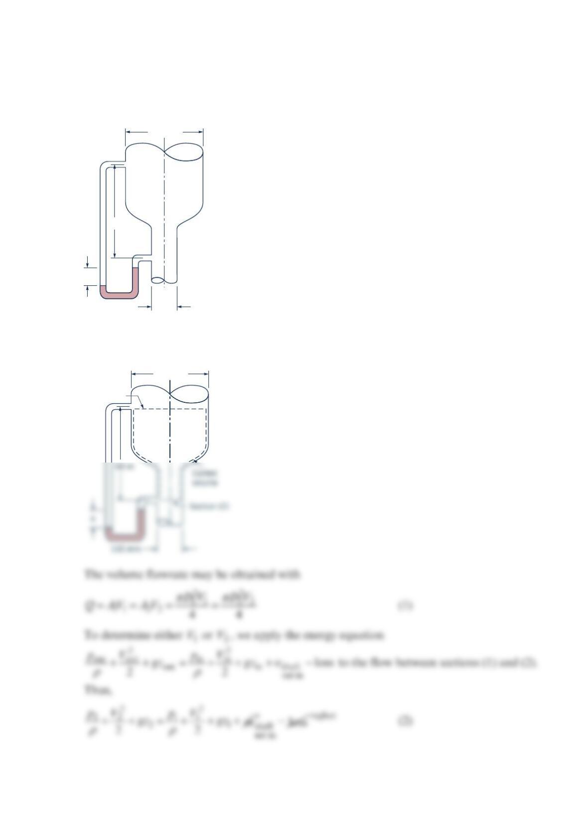
Oil (
1
0 psi) flows downward through a vertical pipe contraction as shown in the figure
below. If the mercury manometer reading, h, is 100 mm, determine the volume flowrate for
frictionless flow. Is the actual flowrate more or less than the frictionless value? Explain.
Solution 5.97
100 mm
h
0.6 m
300 mm
300 mm
Section (1)
Combining Eqs. (1) and (2), we obtain
or
Problem 5.98
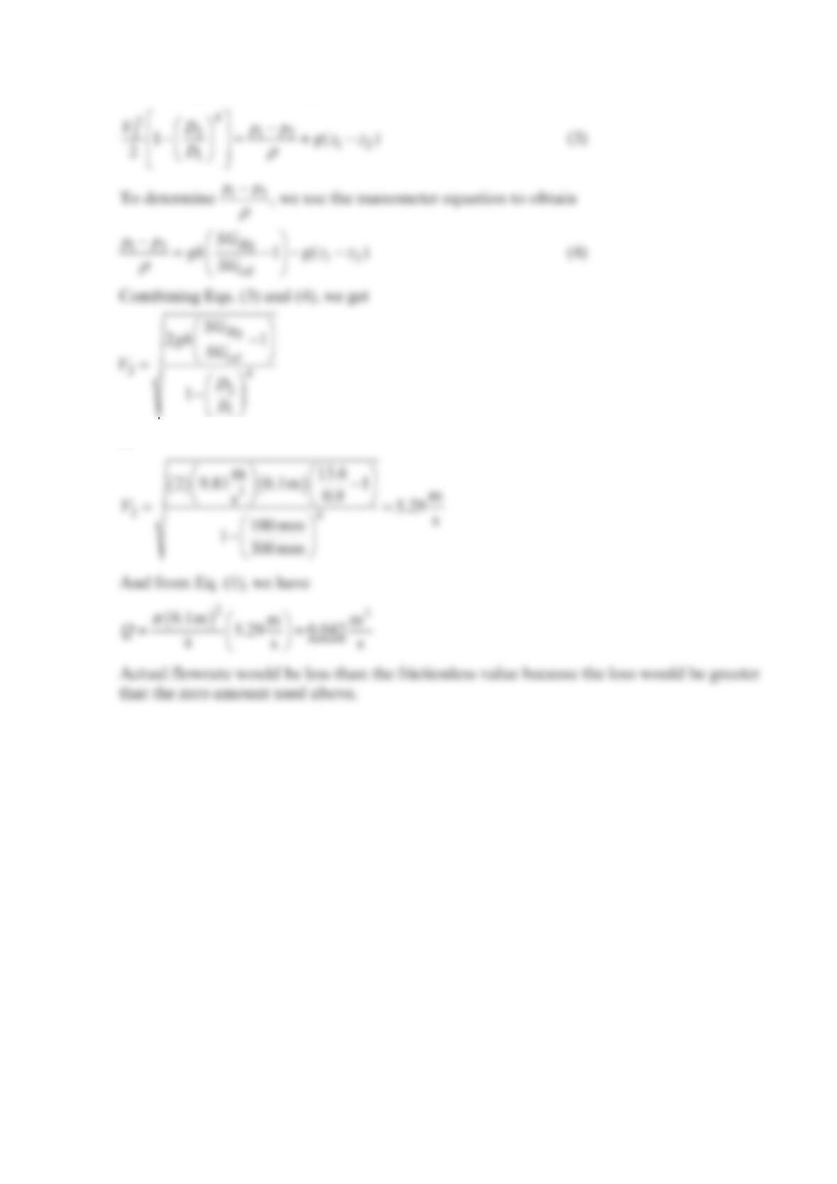
An incompressible liquid flows steadily along the pipe shown in the figure below.
Determine the direction of flow and the head loss over the 6-m length of pipe.
Solution 5.98
0.75 m
1.0 m
1.5 m
6 m
3 m
0.75 m
1.0 m
(2)
(1)
1.5 m
6 m
3 m
Problem 5.99
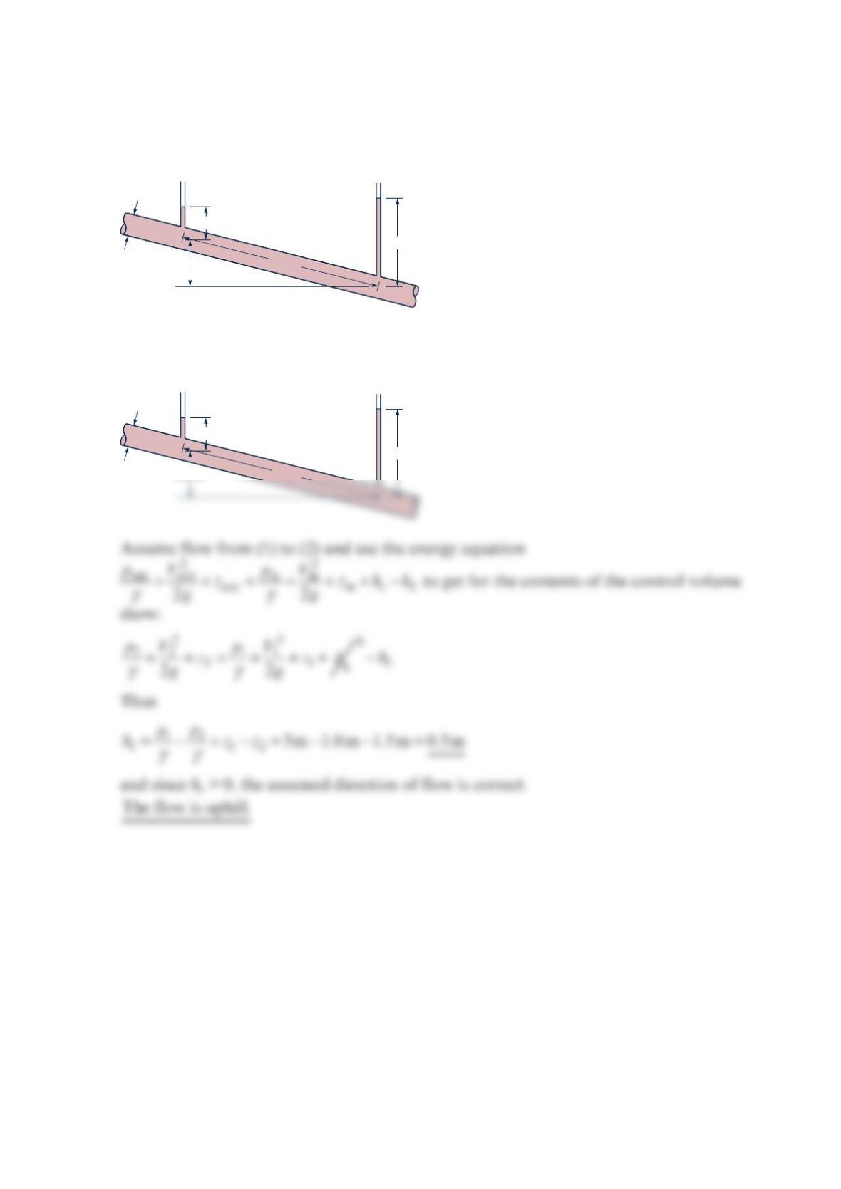
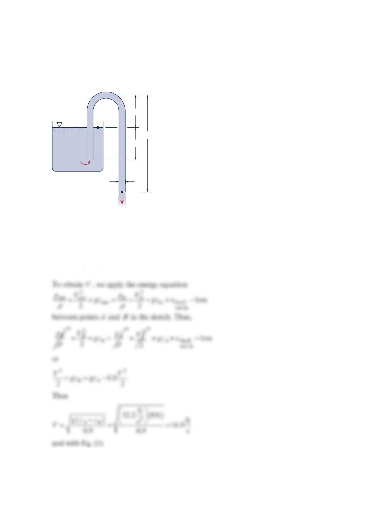
A siphon is used to draw water at 70 °F from a large container as indicated in the figure
below. The inside diameter of the siphon line is 1in. and the pipe centerline rises 3 ft above
the essentially constant water level in the tank. Show that by varying the length of the
siphon below the water level,
h
, the rate of flow through the siphon can be changed.
Assuming frictionless flow, determine the maximum flowrate possible through the siphon.
The limiting condition is the occurrence of cavitation in the siphon. Will the actual
maximum flow be more or less than the frictionless value? Explain.
Solution 5.99
The flowrate, Q, can determined with
π
==
2
4
B
BB B
D
QAV V
(1)
or
1 in.
3 ft
h
3 ft
A
C
We apply the energy equation (see above) between points A and C to get
ρ
ρ
++ =
0
2
2
A
CC C
p
pV gz +
0
2
2
A
V++
0
shaft net in
Aw
gz −0
loss (4)
Using absolute instead of gage pressures we obtain with Eq. (4)
Since
π
==
2
4
C
CC C
D
QAV V
we have for the maximum flowrate through the siphon,
Problem 5.100
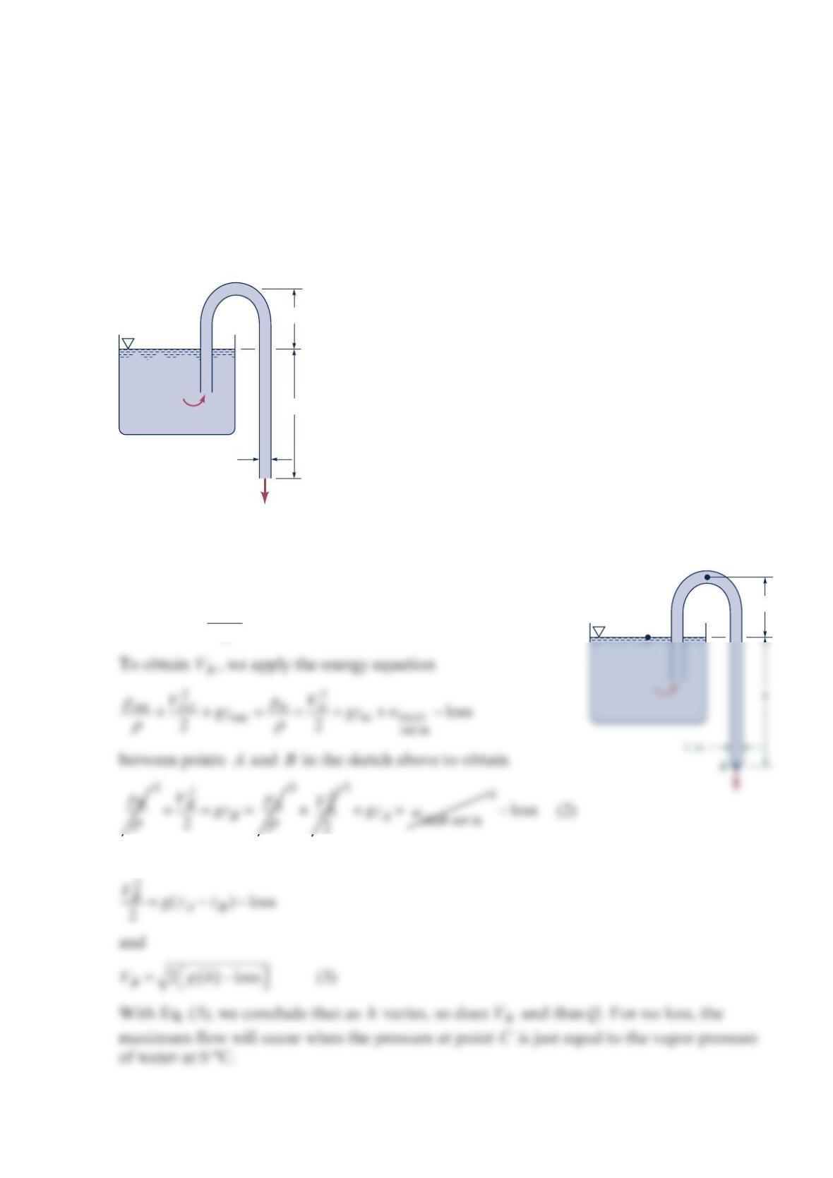
A water siphon having a constant inside diameter of 3in. is arranged as shown in the figure
below. If the friction loss between A and B is 2
0.8 /2V, where V is the velocity of flow in
the siphon, determine the flowrate involved.
Solution 5.100
To determine the flowrate, Q, we use
π
==
2
4
D
QAV V
(1)
A
4 ft
4 ft
12 ft
3 in.
B
Problem 5.101
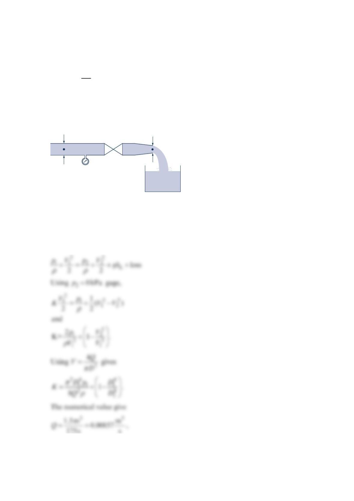
The figure below shows a test rig for evaluating the loss coefficient,
K
, for a valve.
Mechanical energy losses in valves are modeled by the equation:
2
,
2
L
V
gh K
=
where L
gh is the mechanical energy loss and
V
is the flow velocity entering the valve. In a
particular test, the pressure gage reads 40 kPa , gage, and the 3
1.5-m catch tank fills in
2min 55s. Calculate the loss coefficient for a water temperature of 20 °C
Solution 5.101
Apply the mechanical energy equation from point 1 to point 2. Assume constant water
density, steady flow in pipe, zero elevation change, and uniform velocity over each flow
area.
Pressure
gage
Valve
Catch tank
12
D
1 = 6 cm
D
2 = 4 cm
Problem 5.102
For the 180° elbow and nozzle flow shown in the figure below, determine the loss in
available energy from sections (1) to (2). How much additional available energy is lost from
section (2) to where the water comes to rest?
Solution 5.102
6 in.
12 in.
Section (2)
Section (1)
y
x
p
1
= 15 psi
V
1
= 5 ft/s
6 in. Control
volume
Section (2)
y
22
4
22
1
2
2
3
1
2
lb in. ft
15 144 5
in. ft 12 in. lb
s11
ft
slugs 26in.
slug
1.94 s
ft
ft lb
926 slug
loss
loss
=+−
⋅
⋅
=
Problem 5.103
An automobile engine will work best when the back pressure at the interface of the exhaust
manifold and the engine block is minimized. Show how reduction of losses in the exhaust
manifold, piping, and muffler will also reduce the back pressure. How could losses in the
exhaust system be reduced? What primarily limits the minimization of exhaust system
losses?
Solution 5.103
We apply the energy equation
()
++=+++ −
22
out in
out out in in shaft
net in
loss
22
VV
p
zp zw
ργ ργρ ρ
to
the flow from the engine block, exhaust manifold interface to the exhaust system exit to get
Problem 5.104
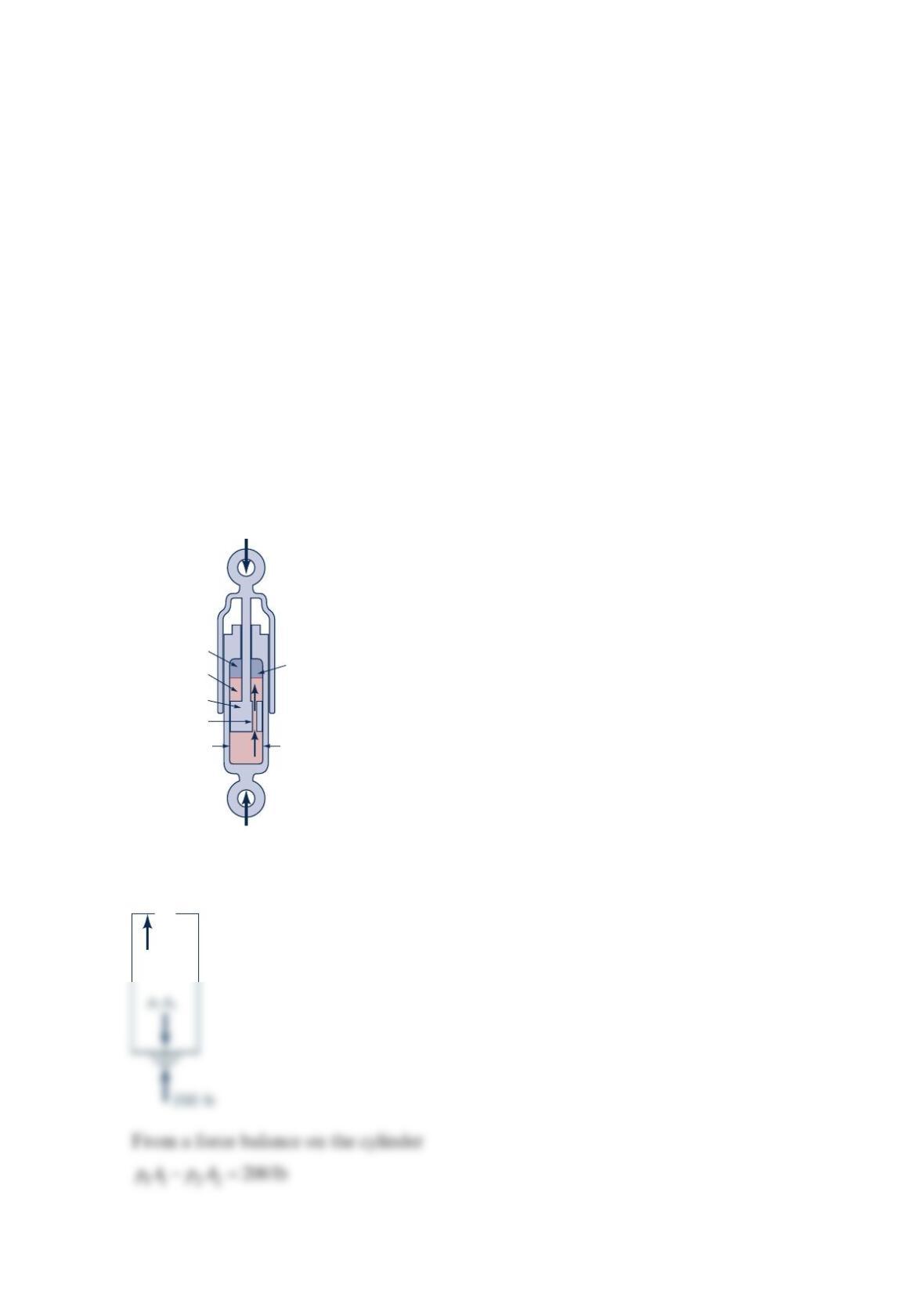
Smart shocks Vehicle shock absorbers are dampers used to provide a smooth, controllable
ride. When going over a bump, the relative motion between the tires and the vehicle body
displaces a piston in the shock and forces a viscous fluid through a small orifice or channel.
The viscosity of the fluid produces a head loss that dissipates energy to dampen the vertical
motion. Current shocks use a fluid with fixed viscosity. However, recent technology has
been developed that uses a synthetic oil with millions of tiny iron balls suspended in it.
These tiny balls react to a magnetic field generated by an electric coil on the shock piston in
a manner that changes the fluid viscosity, going anywhere from essentially no damping to a
solid almost instantly. A computer adjusts the current to the coil to select the proper
viscosity for the given conditions (i.e., wheel speed, vehicle speed, steering-wheel angle,
lateral acceleration, brake application, and temperature). The goal of these adjustments is
an optimally tuned shock that keeps the vehicle on a smooth, even keel while maximizing
the contact of the tires with the pavement for any road conditions. (See Problem 5.104.)
A 200-lb force applied to the end of the piston of the shock absorber shown in the figure
below causes the two ends of the shock absorber to move toward each other with a speed of
5
ft/s. Determine the head loss associated with the flow of the oil through the channel.
Neglect gravity and any friction force between the piston and cylinder walls.
Solution 5.104
Piston
Oil
Channel
1-in. diameter
p
= 0
200 lb
Gas
p
2
A
2
From the energy equation,
Thus
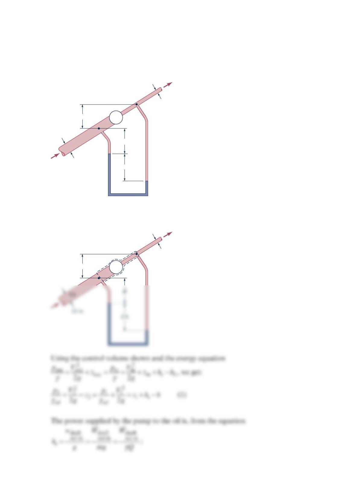
Problem 5.106
Oil ( = 0.88SG ) flows in an inclined pipe at a rate of 3
5ft /s as shown in the figure below.
If the differential reading in the mercury manometer is 3ft , calculate the power that the
pump supplies to the oil if head losses are negligible.
Solution 5.106
12 in.
Oil
3 ft
H
h
6 in.
P
h
6 in.
(1)
(2)
P
From the manometer equation, we get:
12
3(3 )
oil Hg oil
p
HHhp
γγ γ
++−++=
thus
12
33
Hg
oil oil oil
p
p
h
γ
γγ γ
+−−=
(3)
Combining Eqs. (1) and (3), we get,
Finally from Eq. (2)
()
3
3
lb ft ft lb
(0.88) 62.4 5 52.9 ft 14500
ss
ft
shaft
net in
W
⋅
==
Problem 5.107
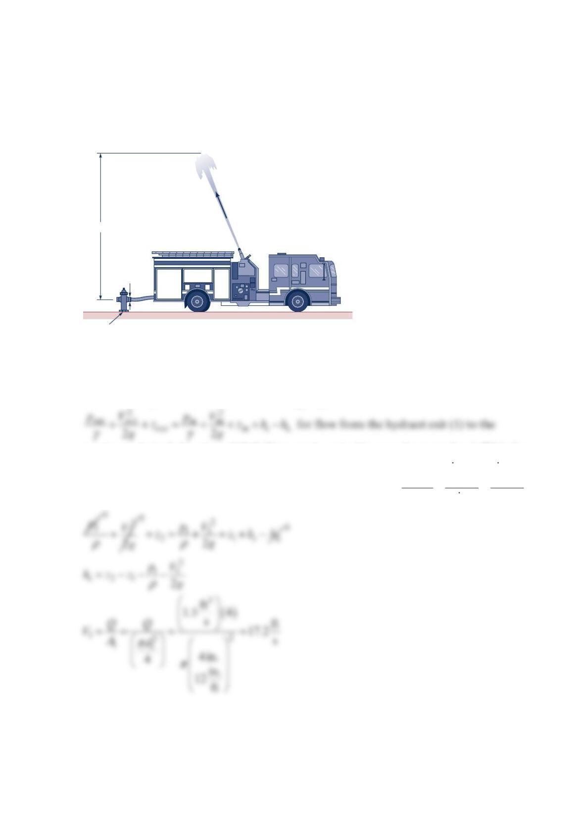
The pumper truck shown in the figure below is to deliver 3
1.5ft /s to a maximum elevation
of 60 ft above the hydrant. The pressure at the 4-in.-diameter outlet of the hydrant is
10 psi . If head losses are negligibly small, determine the power that the pump must add to
the water.
Solution 5.107
To solve this problem, we first use the energy equation
maximum desired elevation of 60 ft (2) to get s
h or in this case, the pump head. With the
pump head, we can get the pump power from the equation
γ
== =
shaft shaft shaft
net in net in net in
s
wWW
hgmg Q
Hydrant
60 ft
10 psi
4-in.
diameter
22
22
32
lb in. ft
10 144 17.2
in. ft s
60 ft lb ft
62.4 2 32.3
ft s
32.3ft
s
s
h
h
=− −
=
Problem 5.108
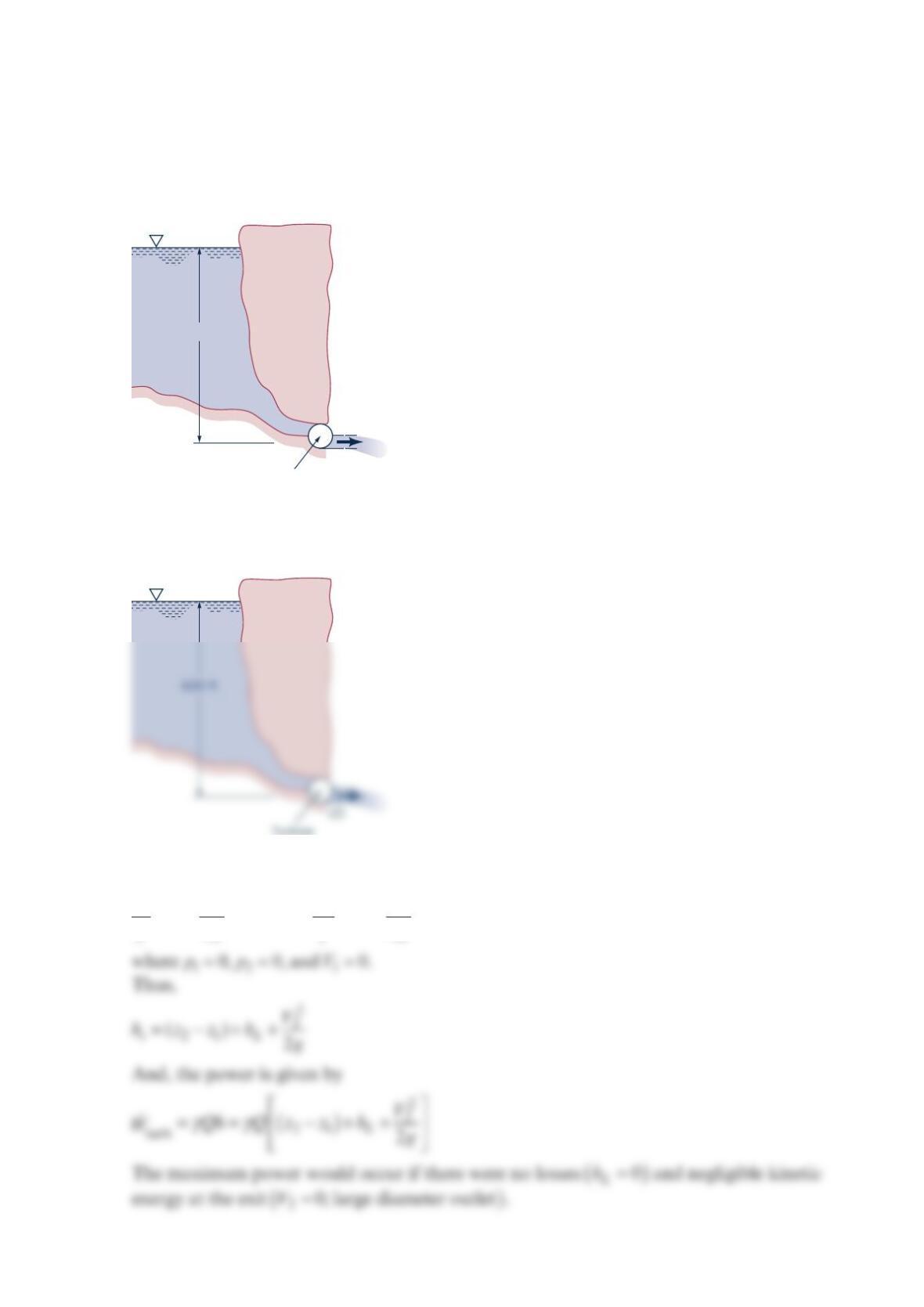
The hydroelectric turbine shown in the figure below passes 8 million gal/min across a head
of 600 ft. What is the maximum amount of power output possible? Why will the actual
amount be less?
Solution 5.108
From the energy equation,
22
11 2 2
12
22
sL
p
VpV
zhh z
gg
γγ
++ +− = + +
600 ft
Turbine
(1)
Turbine
Thus,
() ()
γ
=−= × −
3
6
21 3
turb
lb gal 1min 1ft
62.4 8 10 600 ft
min 60s 7.48gal
ft
Qz z
W