Problem 5.35
Find the force components x
F
and
y
F
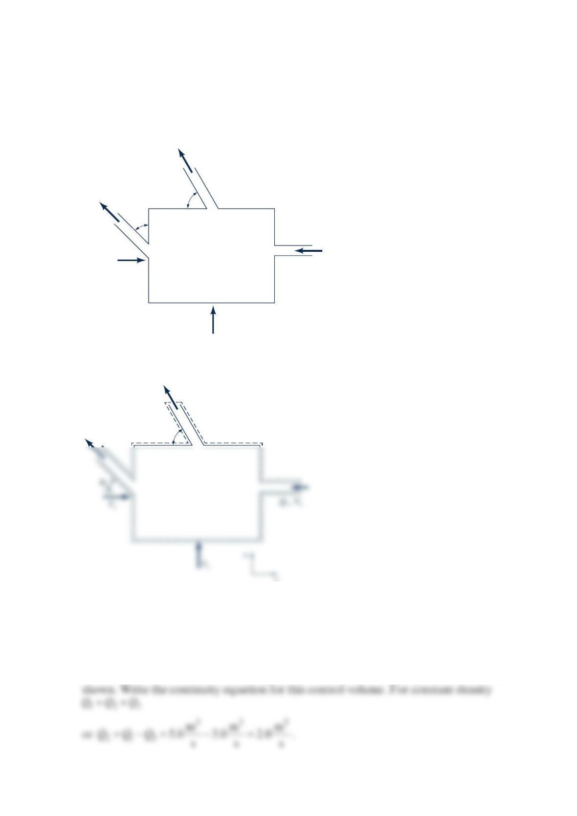
required to hold the box as shown in the figure below
stationary. The fluid is oil and has specific gravity of 0.85. Neglect gravity effects.
Atmospheric pressure acts around the entire box. Steady flow conditions prevail.
Solution 5.35
GIVEN: Fluid is oil with SG = 0.85. Neglect gravity effect. Atmospheric pressure acts over
entire box steady state.
FIND: Force components x
F
and
y
F
hold box stationary.
SOLUTION:
Consider the control volume enclosing the entire box. Consider the positive directions as
Q1 = 5 m3/s
V1 = 2.0 m/s
Q3 = 3.0 m3/s
V3 = 1.5 m/s
3 = 60°
V2 = 2.0 m/s
Fx
Fy
θ
2 =
θ
45°
Q3, V3
Q2, V23
θ
x
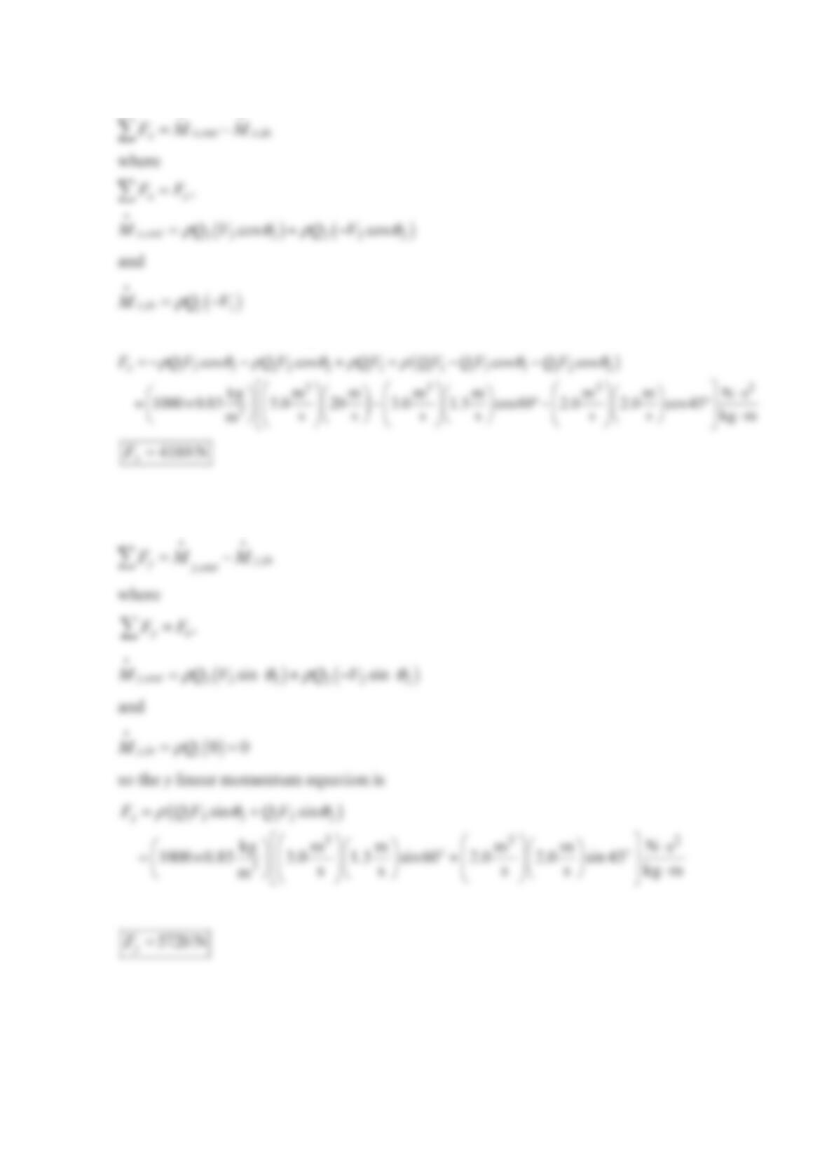
Now write the linear momentum equation in the x-direction for the control volume.
So the linear momentum equation is
Writing the linear momentum equation is the y-direction gives
Problem 5.37
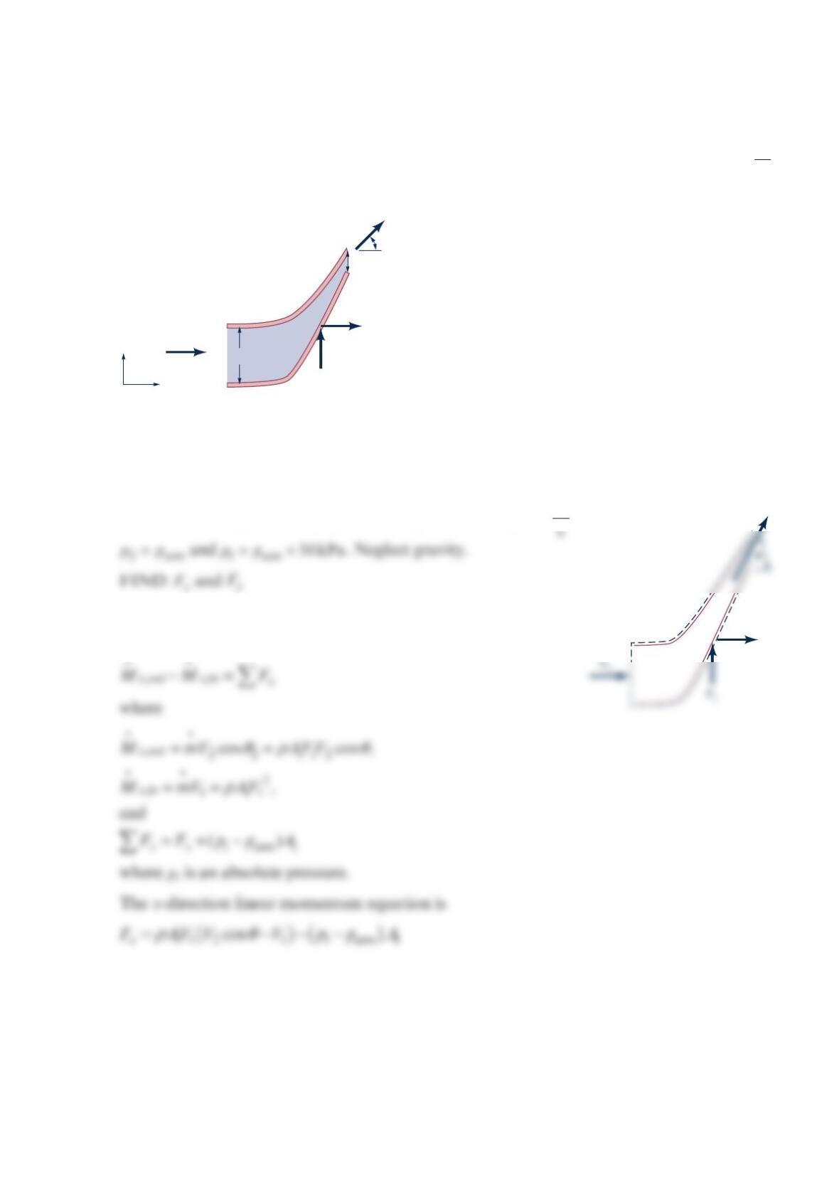
Find the horizontal and vertical forces to hold stationary, the nozzle as shown in the figure
below. The fluid flowing through it is 10 °C liquid water; 22
12 1
m
1.0m , 0.25m , 20 ,
s
A
AV== =
21
and 30 kPa
atm atm
p
ppp==+
. Neglect gravity.
Solution 5.37
GIVEN: 10 °C liquid water, == =
22
12 1
m
1.0 m , 0.25 m , 20 s
AA V
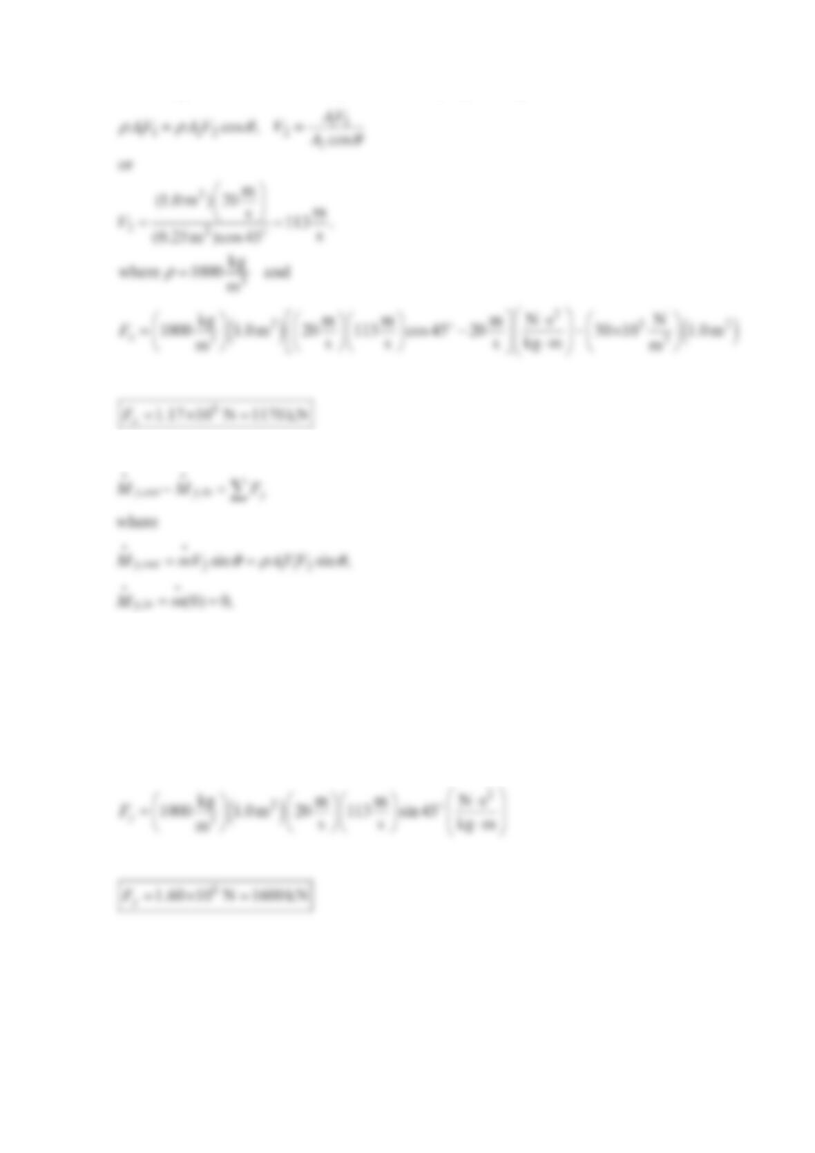
SOLUTION: Apply the linear momentum equation in the x–
direction to the control volume shown on the ring.
p
A
2,
p
2 =
p
atm
45°
F
x
F
y
p
atm
V
1 = 20 m/s
y
x
A
1
p
1
V2
Fx
Assuming constant fluid density, the continuity equation gives
We now apply the linear momentum equation in the y-direction to the control volume.
and
=
y
y
FF
The y-direction linear momentum equation is
ρ
θ
=112
sin .
y
FAVV
The numerical values give
Problem 5.38
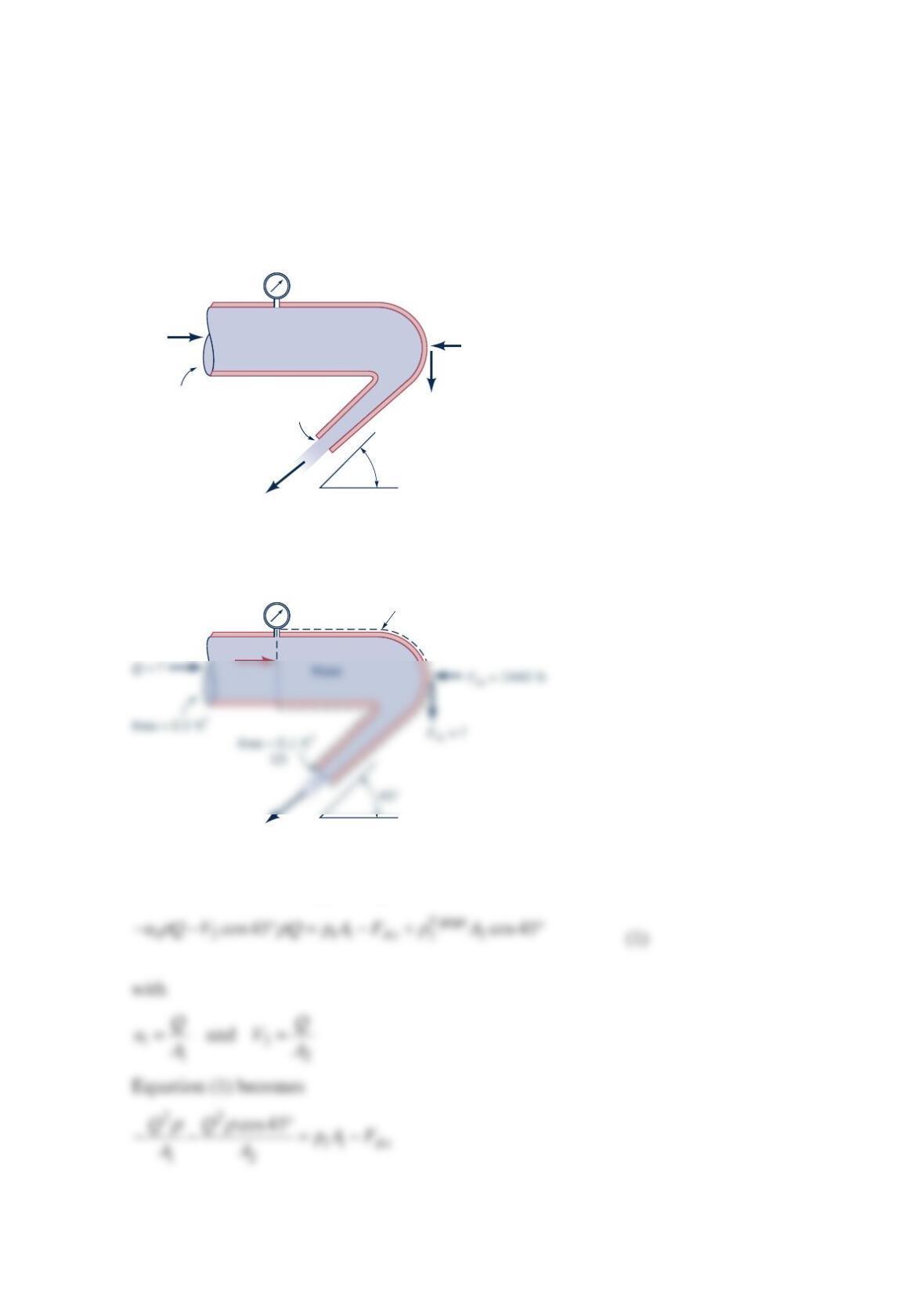
Water flows through a horizontal bend and discharges into the atmosphere as shown in the
figure below. When the pressure gage reads 10 psi, the resultant x-direction anchoring
force, Ax
F
, in the horizontal plane required to hold the bend in place is shown on the figure.
Determine the flowrate through the bend and the y-direction anchoring force, Ay
F
, required
to hold the bend in place. The flow is not frictionless.
Solution 5.38
A control volume that contains the bend and the water within the bend between sections (1)
and (2) as shown in the sketch above is used. Application of the x-direction component of
the linear momentum equation yields
Water
Bend
45°
F
Ax = 1440 lb
F
Ay = ?
Q
= ?
Area = 0.2 ft2
Area = 0.1 ft2
10 psi
Bend
Control
volume
10 psi
p
1
A
1
(1)
or for part (a)
11
21
cos 45 1
Ax
pA F
Q
AA
ρ
−+
=
+
For part (b), we use the y-direction component of the linear momentum equation to get
and
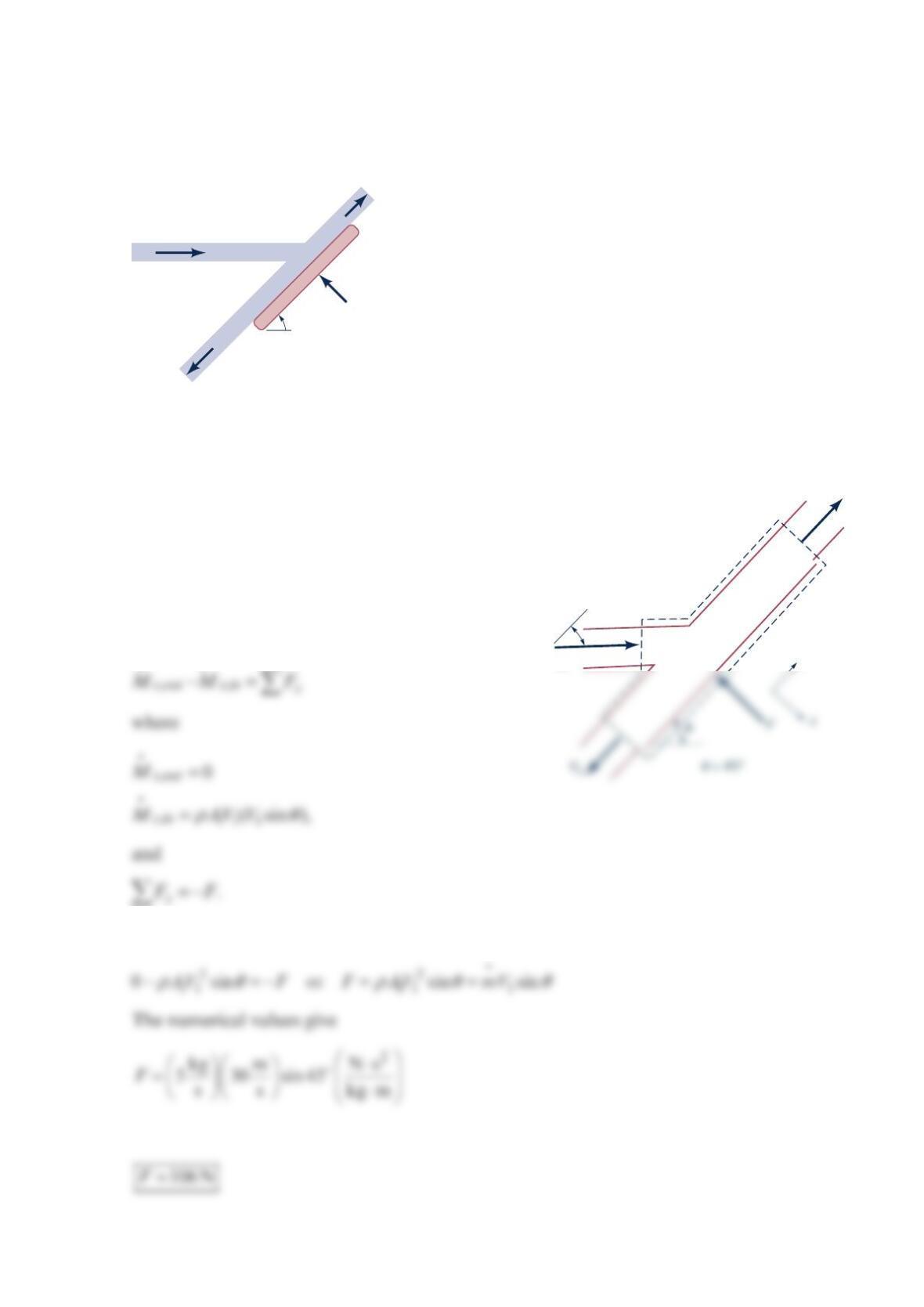
Problem 5.39
Find the magnitude of the force
F
required to hold the plate in the figure below stationary.
Solution 5.39
GIVEN: Plate hit with water in the figure in the
problem. Neglect gravity. Frictionless plate.
FIND: Force
F
to hold plate stationary.
SOLUTION: Assume steady flow and apply the
linear momentum equation in the x-direction to the
control volume shown.
F
is the force on the plate.
The x-direction linear momentum equation is then
V
1
= 30 m/s
V
2
V
3
F
45°
Water
m = 5 kg/s
∙
V2
V1
θ
y
Problem 5.40
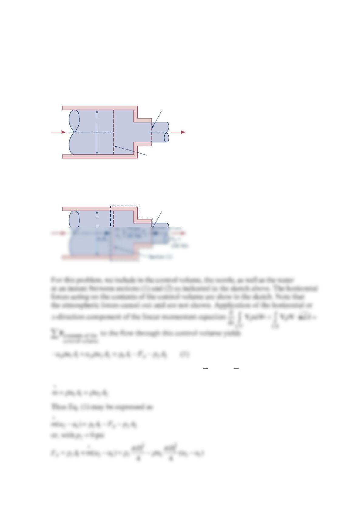
Water enters the horizontal, circular cross-sectional, sudden contraction nozzle sketched in
the figure below at section (1) with a uniformly distributed velocity of 25ft/s and a pressure
of 75 psi . The water exits from the nozzle into the atmosphere at section (2) where the
uniformly distributed velocity is 100 ft/s . Determine the axial component of the anchoring
force required to hold the contraction in place.
Solution 5.40
From the conservation of mass equation 12
11 2 2
mAV AV
ρρ
==
, we obtain
D1
= 3 in.
p1
= 75 psi
V1
= 25 ft/s
p2
=
0 psi
V2
=
100 ft/s
Section (2)
Section (1)
D1
= 3 in.
p2
=
Section (2)
a
nd
Problem 5.42
Exhaust (assumed to have the properties of standard air) leaves the 4-ft-diameter chimney
shown in the figure below with a speed of 6 ft/s . Because of the wind, after a few diameters
downstream, the exhaust flows in a horizontal direction with the speed of the wind, 15 ft/s .
Determine the horizontal component of the force that the blowing wind exerts on the
exhaust gases.
Solution 5.42
For the control volume indicated the x-component of the momentum equation
becomes
x
CS udAF
ρ
⋅=
Vn
222 X
V
VA R
ρ
=, where X
R
is the net horizontal force that the wind puts on the exhaust gases.
Thus,
15 ft/s
15 ft/s
6 ft/s
4 ft
15 ft/s
cs
V
2
= 15 ft/s
(2)
Problem 5.43
Air at =
1300 KT, =
1303kPap, and =
10.5 m/sV enters the Venturi as shown in the figure
below. The air leaves at =
2220 KT and =
2101kPap; =2
10.6 mA and =2
21.0 mA.
Calculate the horizontal force required to hold the Venturi stationary.
Solution 5.43
FIND: Horizontal force to hold ventori stationary.
SOLUTION:
Apply the linear momentum equation in the x-direction to the control volume enclosing the
ventori.
V
1
= 0.5 m/s
T
1
,
p
1
V
2
T
2
,
p
2
p
atm
= 101 kPa
F
Assuming the air is an ideal gas
2
V
is fluid from the continuity equation,
ρρ
=
111 2 22
or
AV A V
Then,
or
Problem 5.44
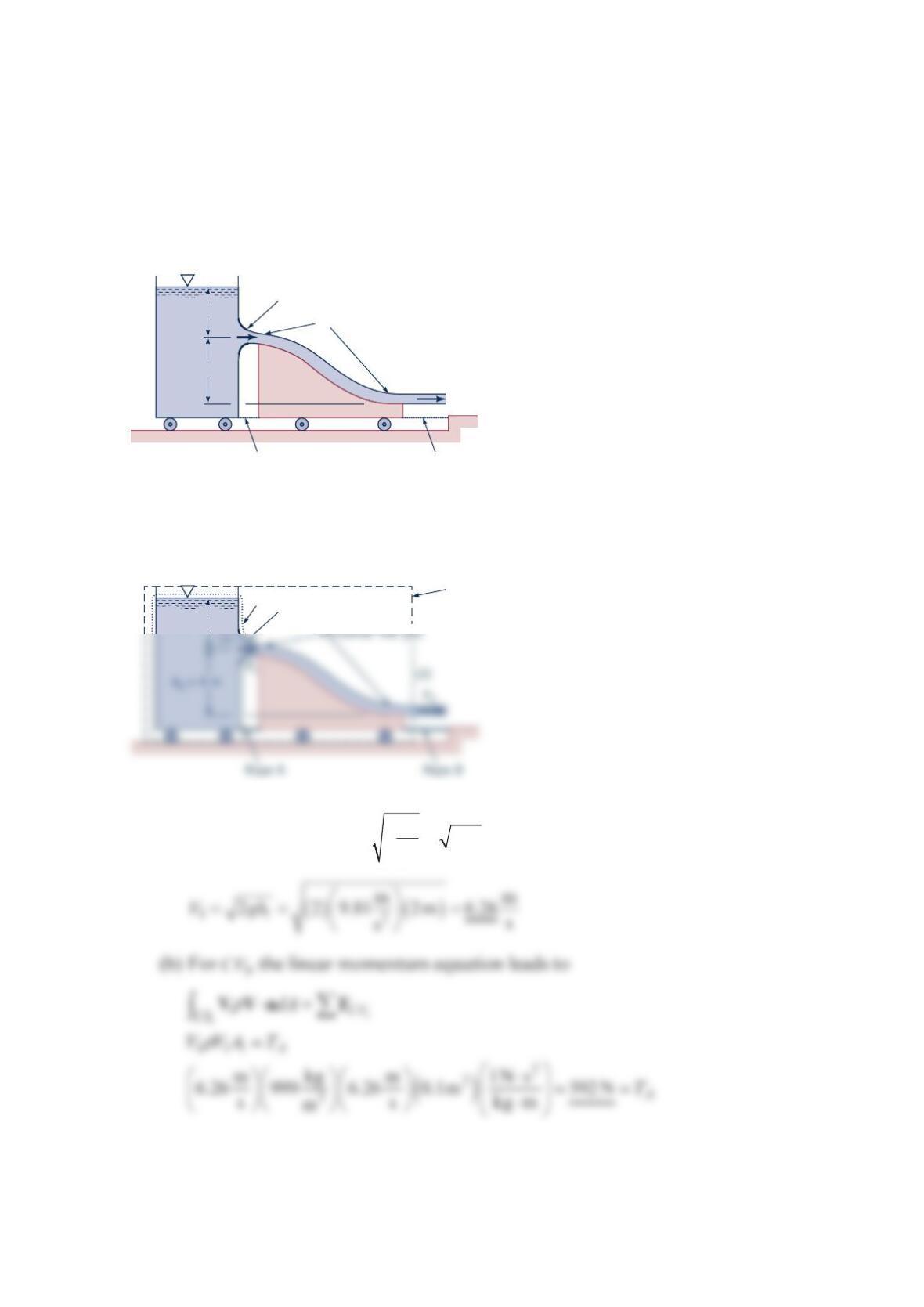
Water flows steadily from a tank mounted on a cart as shown in the figure below. After the
water jet leaves the nozzle of the tank, it falls and strikes a vane attached to another cart.
The cart’s wheels are frictionless, and the fluid is inviscid. (a) Determine the speed of the
water leaving the tank, 1
V
, and the water speed leaving the cart, 2
V
. (b) Determine the
tension in rope A. (c) Determine the tension in rope
B
.
Solution 5.44
(a) From the equation 22
h
V
gh
γ
ρ
==
, we get
V
2
V
1
2 m
4 m
Nozzle area = 0.01 m
2
Horizontal free jets
Rope A Rope B
h
1
= 2 m
Nozzle area = 0.01 m
2
CV
2
CV
1
(c) For 2
CV , the linear momentum equation leads to
A
lso, from conservation of mass
V
Problem 5.45
Determine the magnitude and direction of the anchoring force needed to hold the
horizontal elbow and nozzle combination shown in the figure below in place. Atmospheric
pressure is 100 kPa (abs) . The gage pressure at section (1) is 100 kPa . At section (2), the
water exits to the atmosphere.
Solution 5.45
The control volume shown in the sketch above is used. Application of the y-direction
component of the linear momentum equation yields
160 mm
300 mm
Section (2)
Section (1)
y
x
Water
V
2
V
1
p
1
= 100 kPa
V
1
= 2 m/s
160 mm
y
V
2
or
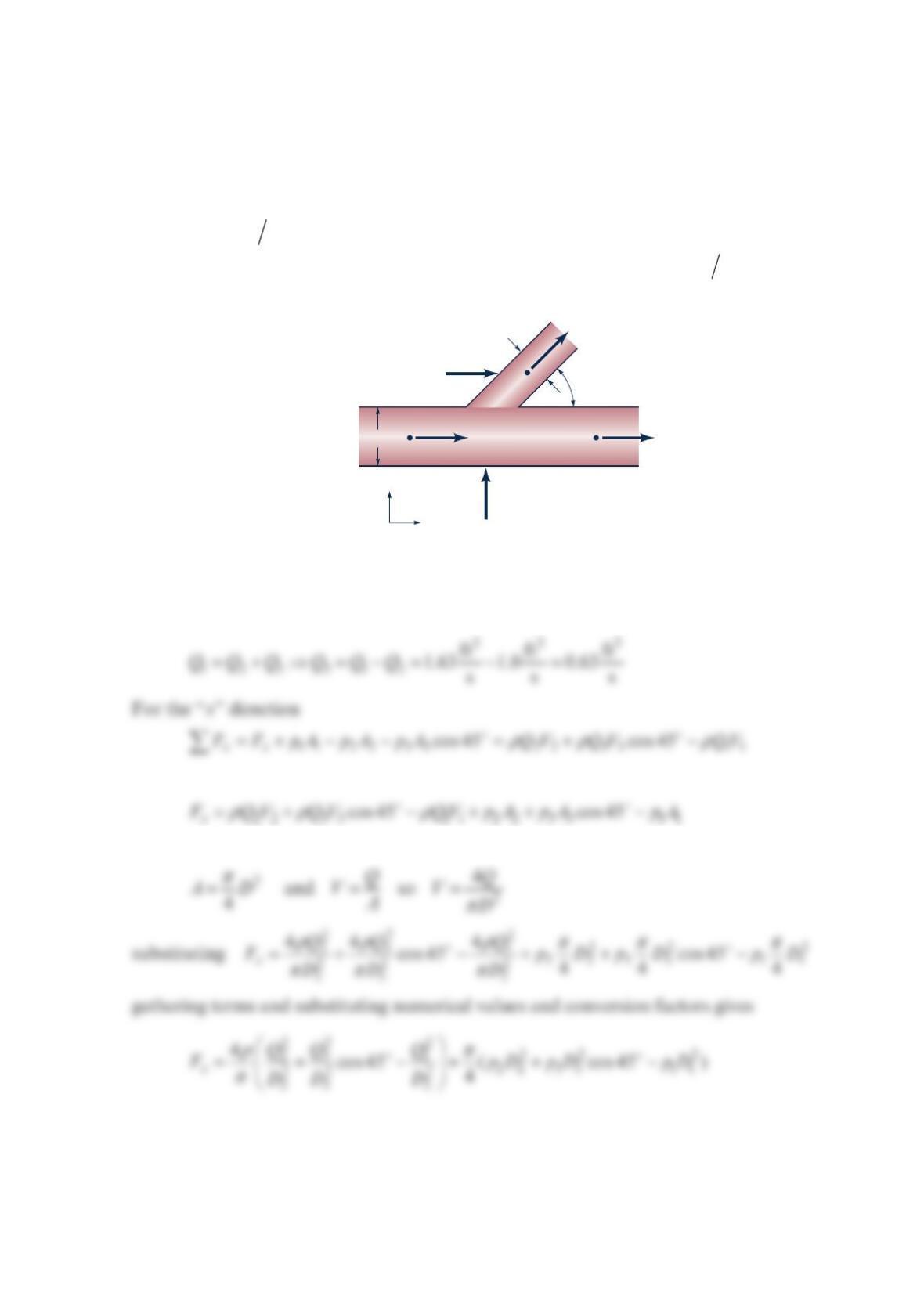
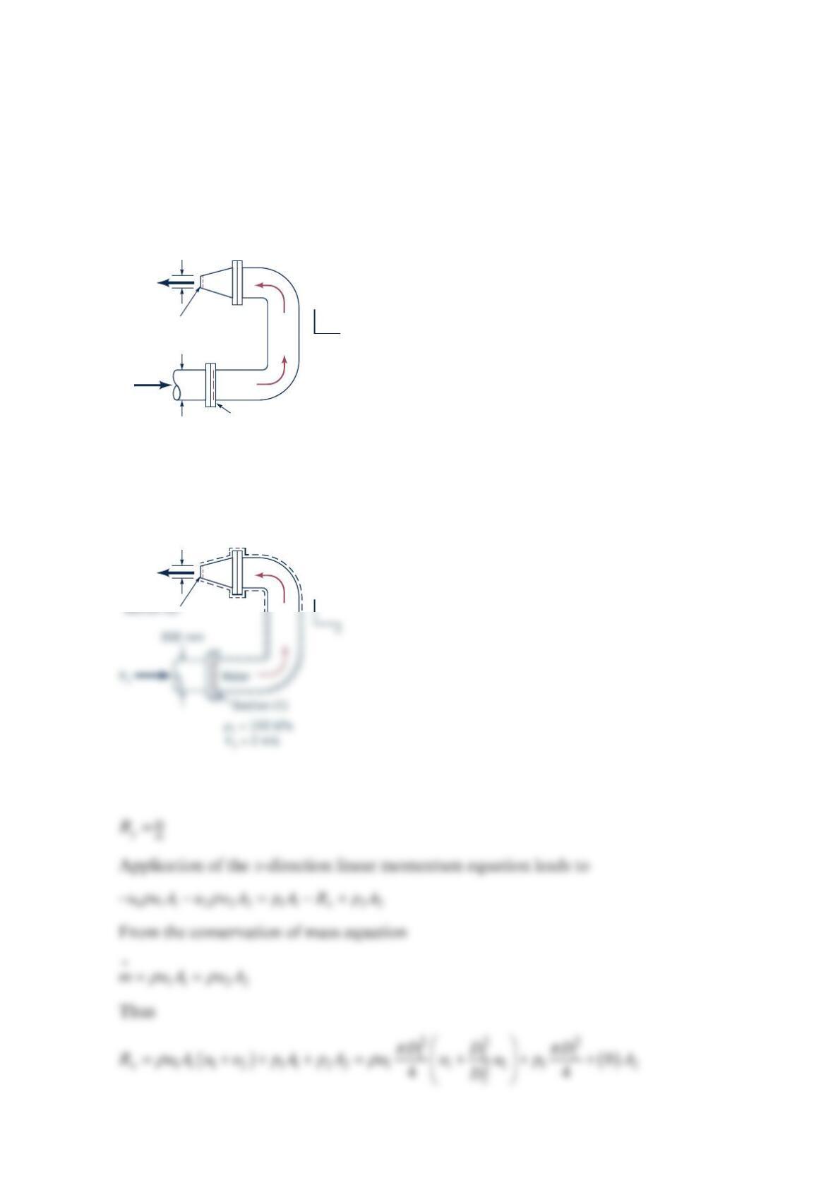
Problem 5.46
The figure below shows a lateral pipe fitting. This particular fitting has a mainline diameter
of 4.0 in. The diameter of the lateral is
3
.0 in., and the lateral angle is 45; 60 °F water is
flowing in the lateral. Measurements show that the pressure at point 1 is 34.0 psig , the
pressure at point 2 is 35.0 psig , the pressure at point 3 is 33.5psig , and the flowrate at
point 2 is 3
1.0 ft s . Determine the horizontal and vertical force components ( x
F
and
y
F
)
required to hold the lateral fitting stationary. Neglect gravity. 3
1=1.63ft sQ.
Solution 5.46
First apply the continuity equation
so
but
D
1
= 4 in.
D3
= 3 in.
Q2
Q3
= 45°
Fx
Fy
x
y
2
θ
Q1
1
3
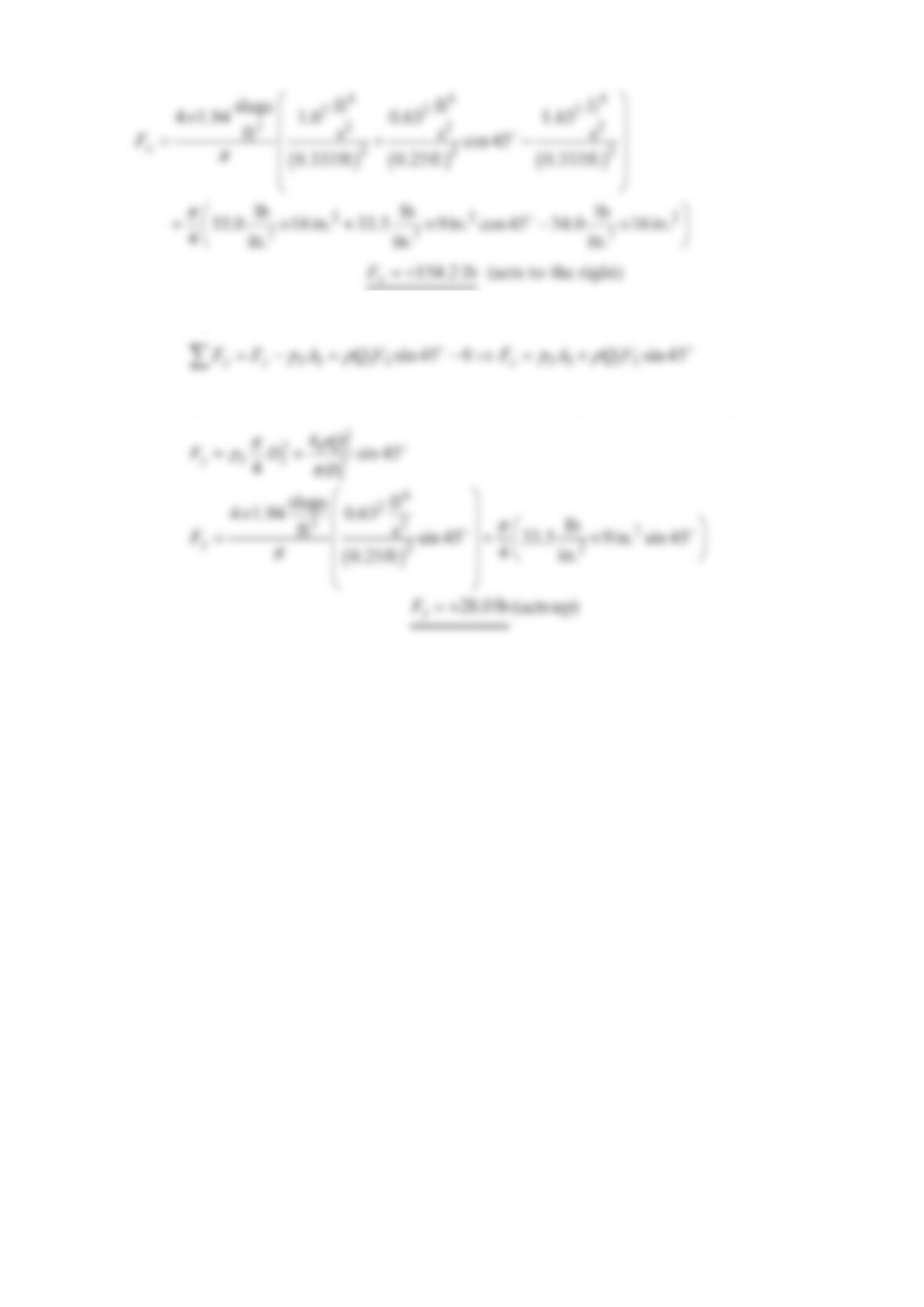
For the “y” direction
The weight of the fitting and the water in it have been neglected. Substituting as before
C. p
2
, A
2
30°
V.
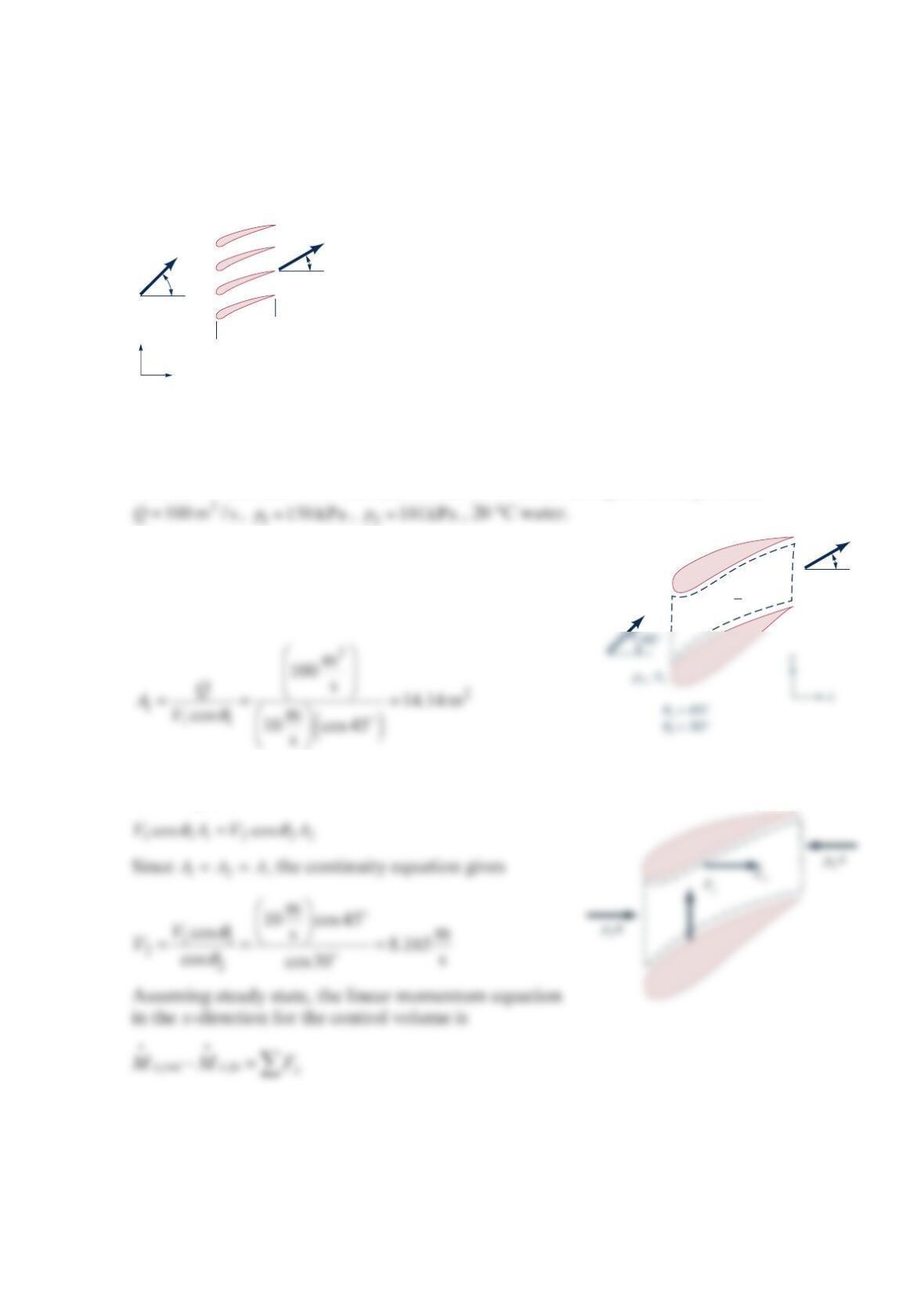
Problem 5.47
Water flows steadily between fixed vanes, as shown in the figure below. Find the x and y
components of the water’s force on the vanes. The total volume flowrate is 3
1
00 m /s,
pressure 1150 kPa
p
=, and pressure 2101 kPa
p
=.
Solution 5.47
GIVEN: Water flows between fixed vanes as shown in the figure in the problem.
FIND: and
XY
F
F
on vanes by water.
SOLUTION: The control volume for flow between two
vanes is shown below. Now
Assuming constant fluid density and applying the continuity equation to the control
volume gives
A
V
1 = 10 m/s
A
2 =
A
1
A
1
x
y
45°
30°
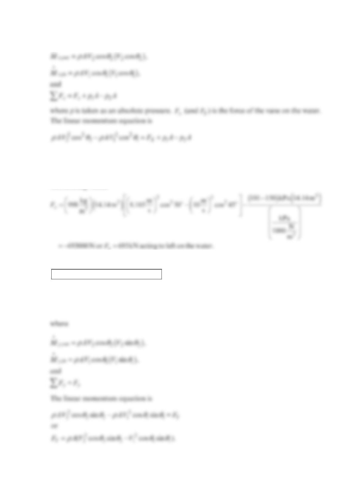
where
or
ρθ θ
=−+−
22 22
221 21
(cos cos)( )
x
FAV V ppA
Substituting values
The force on the vane is
= 693kN acting to right on vanes.
x
F
The linear momentum equation in the y-direction for the control volume is
,,y out y in
y
M
MF−=