and we note that the result is independent of the fluid involved. The value of ,1
V
θ
can be
ascertained with the help of the section (1) velocity triangle sketched below.
11
s1.8 s
Ar
Thus with Eq. (2), we obtain
θ
==
,1
mm
6.7 tan60 11.6
ss
V
V
Problem 5.90
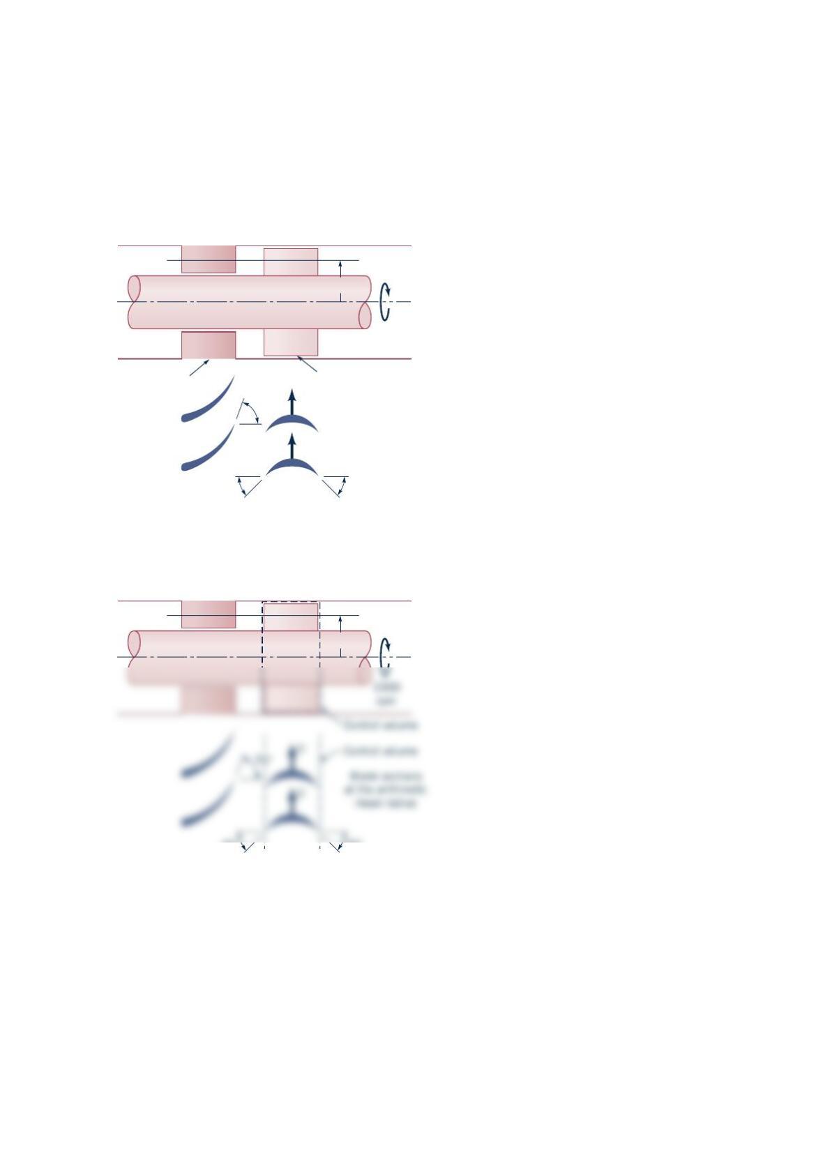
A sketch of the arithmetic mean radius blade sections of an axial-flow water turbine stage is
shown in the figure below. The rotor speed is 1000 rpm . (a) Sketch and label velocity
triangles for the flow entering and leaving the rotor row. Use V for absolute velocity,
W
for
relative velocity, and
U
for blade velocity. Assume flow enters and leaves each blade row at
the blade angles as shown. (b) Calculate the work per unit mass delivered at the shaft.
Solution 5.90
U
U
70°
45°45°
Blade sections
at the arithmetic
mean radius
Stator Rotor
1000
rpm
r
m = 6 in.
45°45°
r
m = 6 in.
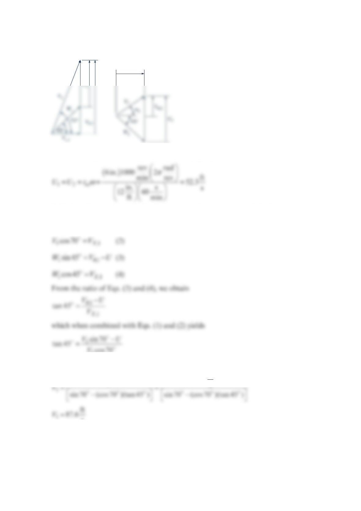
The velocity triangles for the flow entering and the flow leaving the rotor row at the
arithmetic mean radius are sketched below.
At the arithmetic mean radius, the blade velocity, ,
U
is
With the velocity triangle for the flow entering the rotor, we conclude that
θ
=
1,1
sin70VV
(1)
1
V
or
ft
52.3 s
U
Vx,2
Then
θ
== =
== =
,1 1
,1
1o
ft ft
sin70 87.6 sin70 82.3
ss
ss
and
ft
29.9 ft
s42.4 s
cos 45 cos 45
X
VV
V
W
With the velocity triangle for the flow leaving the rotor, we conclude that
From the conservation of mass equation
Thus from Eq. (5)
ss s
The ratio of Eqs. (7) and (8) yields
θ
α
−−
== =
,2
11
2
,2
ft
22.4 s
tan tan 37
ft
29.9 s
X
V
V
and from Eq. (7)
We can use the equation ()( )
shaft in in out out
wUVUV
θθ
=− ± + ± to calculate the work per unit
mass delivered at the shaft. Thus
1,1 2,2
shaft
wUVUV
θθ
=− +
Problem 5.92
An incompressible fluid flows along a 0.20-m-diameter pipe with a uniform velocity of
3
m/s. If the pressure drop between the upstream and downstream sections of the pipe is
2
0 kPa, determine the power transferred to the fluid due to fluid normal stresses.
Solution 5.92
From the equation, normal
stress CS CS
dA p d
A
W
σ
=⋅=−⋅
Vn Vn
,
but
π
== == =
22
12 1 2
m
3 , (0.20 m) 0.0314 m
s4
VV AA
Problem 5.93
A horizontal Venturi flow meter consists of a converging–diverging conduit as indicated
in the figure below. The diameters of cross sections (1) and (2) are
6
and 4 in. The velocity
and static pressure are uniformly distributed at cross sections (1) and (2). Determine
the volume flowrate ( 3
ft /s ) through the meter if −=
12 3psipp , the flowing fluid is
oil ( =3
56 lbm/ftp), and the loss per unit mass from (1) to (2) is negligibly small.
Solution 5.93
Application of the energy equation
22
loss
22
out out in in
out in
pV pV
gz gz
ρρ
++ =++−
to the flow through this control volume yields
Section (2)
Section (1)
D
1
= 6 in.
D
2
= 4 in.
Section (1)
Control volume
D
1
= 6 in.
⋅
2
22 2
lb in. lbm ft
3 144 32.2 lb
in. ft s 1
1
2
Problem 5.94
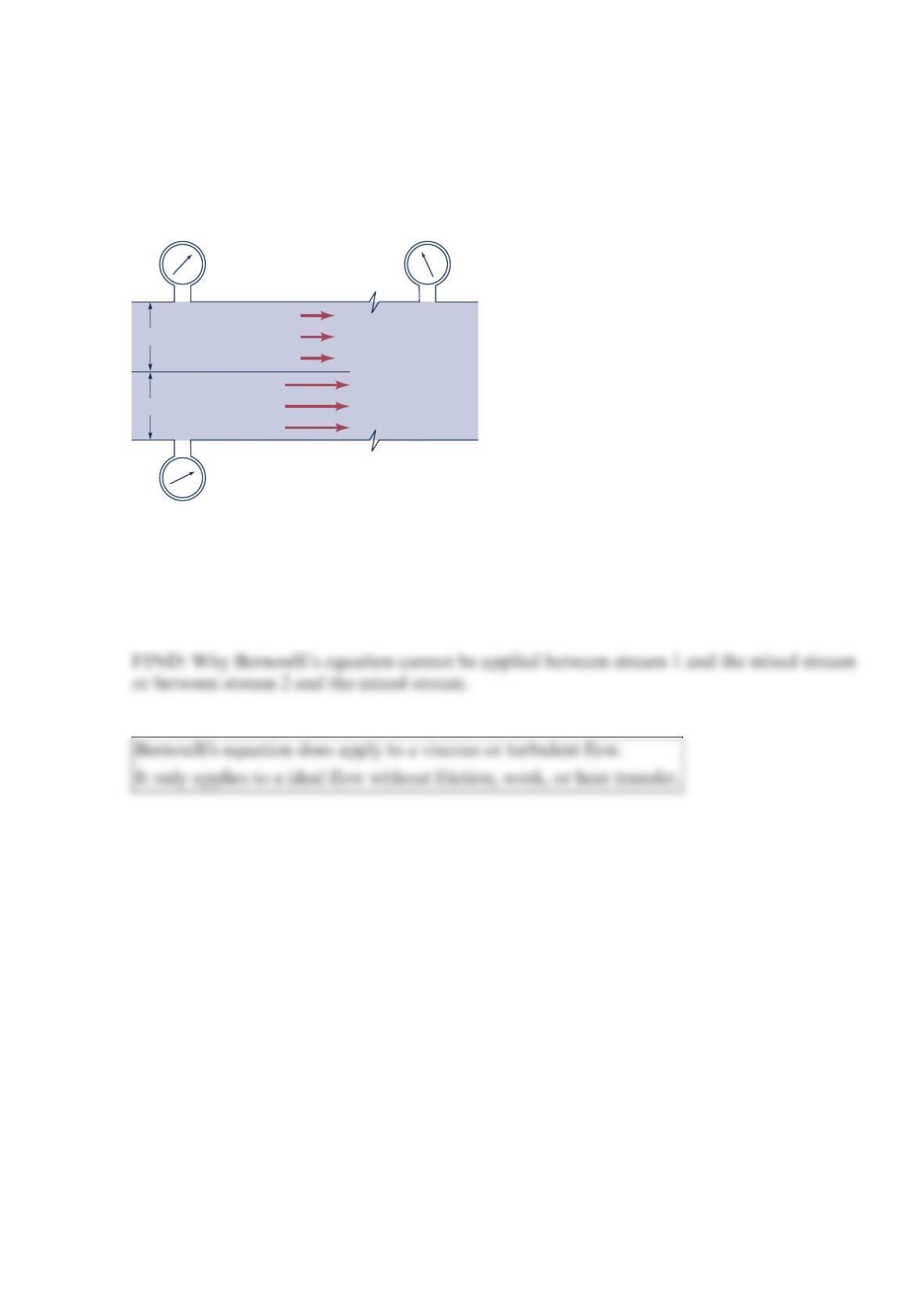
The figure below shows the mixing of two streams. The shear stress between each fluid and
its adjacent walls is negligible. Why cannot Bernoulli’s equation be applied between points
in stream 1 and the mixed stream or between points in stream 2 and the mixed stream?
Solution 5.94
GIVEN: The figure in the problem with negligible shear stress between fluids and wall.
SOLUTION: The mixing of two streams requires turbulence and/or viscous action and
p
1
= 50 psia
p
2
= 50 psia
p
3
2 ft
2
p
1
= 62.4 lbm/ft
3
2 ft
2
p
2
= 62.4 lbm/ft
3
5 ft/s
10 ft/s
Problem 5.95
Liquid water at 40 F
flows down a vertical, thermally insulated,
2
-in. schedule 40 steel
pipe. The temperature change of the water is related to its internal energy change by
()
−= −
⋅
21 21
Btu
32.2 slug F
uu TT
.
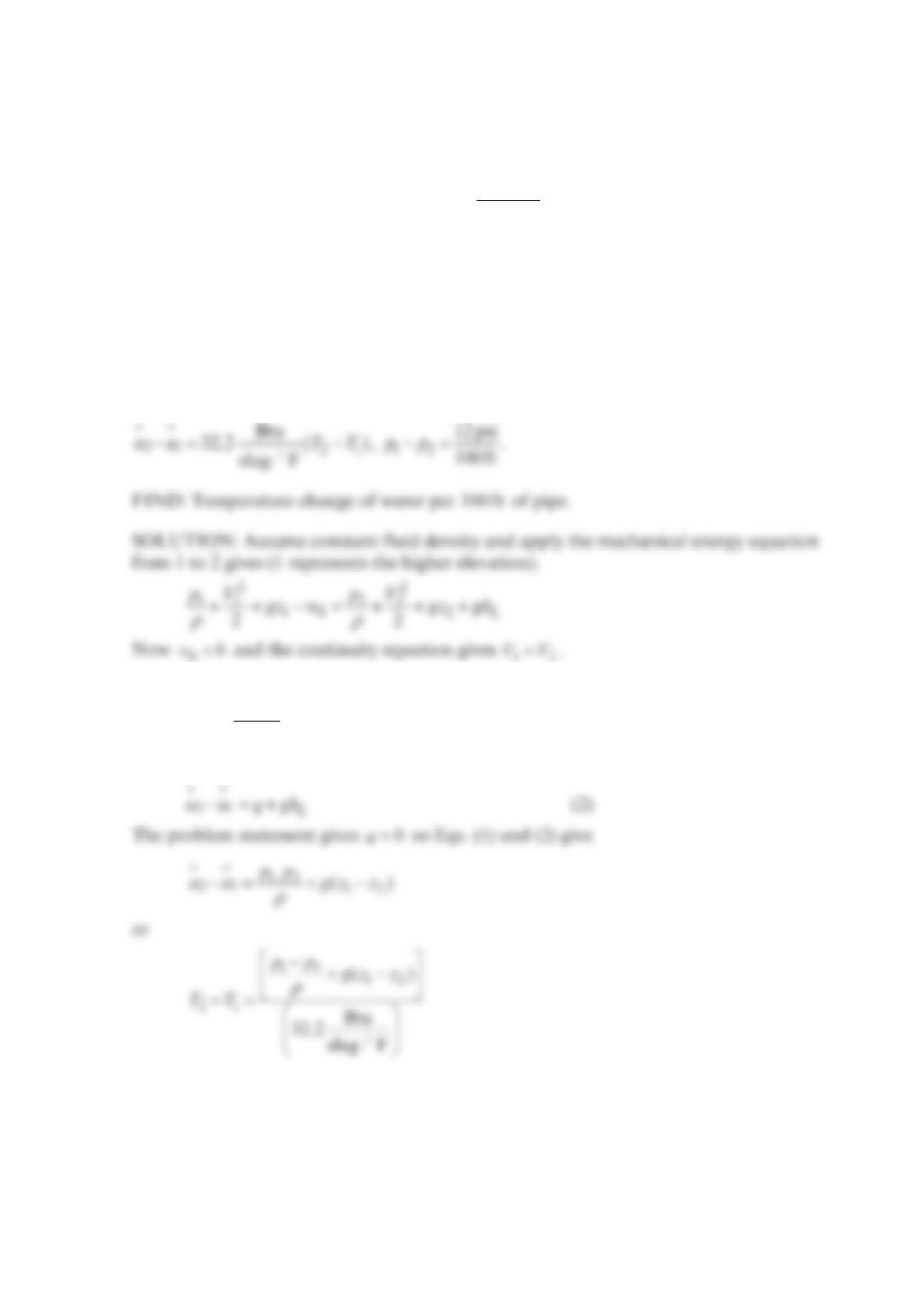
What is the temperature change of the water per 100 ft of drop if the pressure drop ( 12
p
p−)
per 100 ft is 12.0 psi ?
Solution 5.95
GIVEN: Liquid water at 40 F
flows down a vertical, thermally insulated,
2
-in. steel pipe.
Then
12 12
()
L
p
p
gh g z z
ρ
−
=+−
. (1)
and
From property table
ρ
=3
slug
1.938 ft so
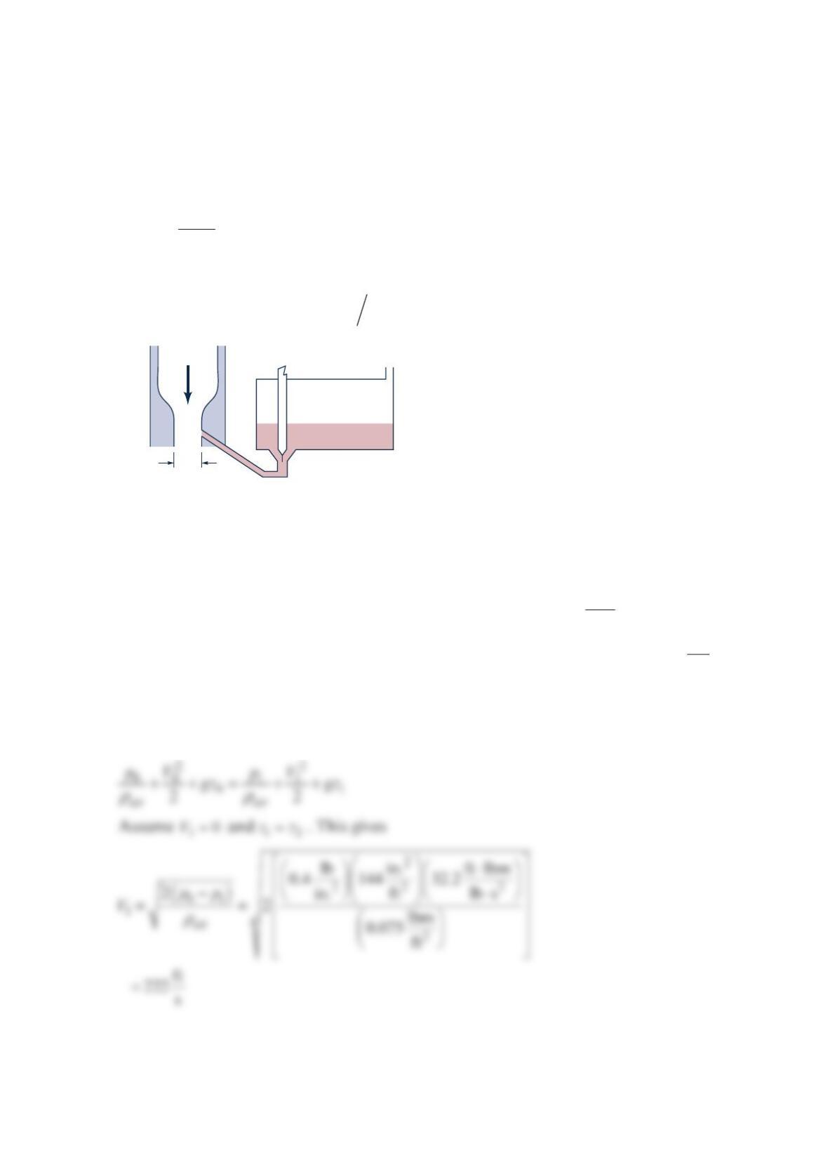
Problem 5.96
A simplified schematic drawing of the carburetor of a gasoline ( 0.75
S
=) engine is shown in
the figure below. The throat area is 2
0.5 in. . The running engine draws air downward
through the carburetor Venturi and maintains a throat pressure of 14.3psia . The low
throat pressure draws fuel from the float chamber and into the air stream. The energy losses
in the 0.07-in.-diameter fuel metering line and valve are given by
2
2
L
KV
gh g
=
,
where 6.0
K
= and
V
is the fuel velocity in the metering line. Assume that the air is an ideal
fluid having a constant density 3
0.075 lbm/ft
A
ρ
=. The atmospheric pressure is
1
4.7 psia.
Calculate the air-to-fuel ratio ( af
mm
).
Solution 5.96
GIVEN: Carburetor shown in the figure in the problem. Throat pressures = 14.3psia ,
atmospheric pressures = 14.7 psia , constant air density 3
lbm
0.075 ft
A
ρ
=. Fuel specific
gravity = 0.75
S
G=. 0.07-in. diameter fuel line has energy loss given by
2
6.0 2
L
V
gh =
FIND: Air/fuel ratio.
SOLUTION: We first find the air flowrate. Assume in viscid flow and apply Bernoulli’s
equation to a streamline from the atmosphere (0) to the throat (1).
0.5 in.2
Air Air vent
Fuel
Float chamber
The air mass flowrate is
The fuel flowrate is found by applying the mechanical energy equation from the float
chamber free surface (2) to the throat (3). For no mechanical work,
Assume 23
zz≈ and 20
V
≈. Using the expression for L
gh gives
22
33 1 1
3
6or V.
22 3.5
atm atm
f
f
VVpp p p
ρρ
−−
+= =
The numerical values give
Then
The air-to-fuel ratio (A/F) is