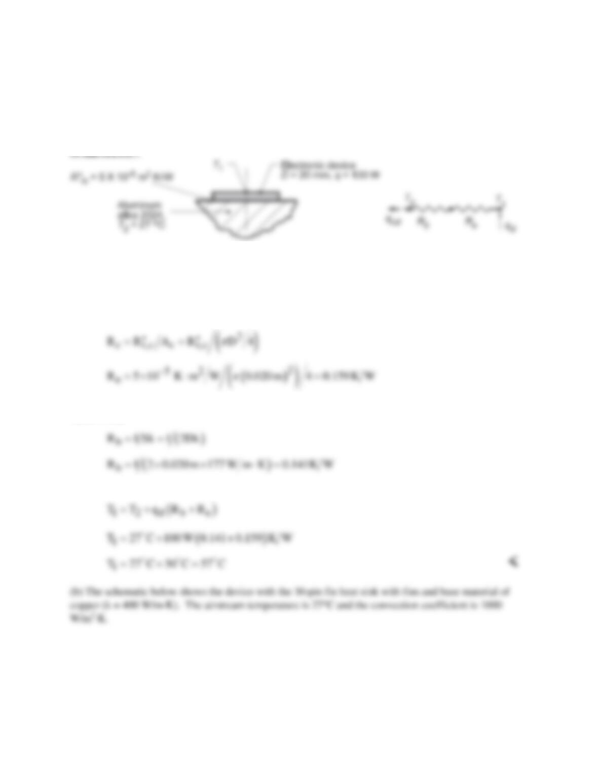
PROBLEM 4.31
KNOWN: Disc-shaped electronic devices dissipating 100 W mounted to aluminum alloy block with
prescribed contact resistance.
FIND: (a) Temperature device will reach when block is at 27°C assuming all the power generated by the
device is transferred by conduction to the block and (b) For the operating temperature found in part (a),
the permissible operating power with a 30-pin fin heat sink.
ASSUMPTIONS: (1) Two–dimensional, steady-state conduction, (2) Device is at uniform temperature,
T1, (3) Block behaves as semi–infinite medium.
PROPERTIES: Table A.1, Aluminum alloy 2024 (300 K): k = 177 W/m⋅K.
ANALYSIS: (a) The thermal circuit for the conduction heat flow between the device and the block
shown in the schematic where Re is the thermal contact resistance due to the epoxy–filled interface,
The thermal resistance between the device and the block is given in terms of the conduction shape factor,
Table 4.1, as
From the thermal circuit,
Continued…
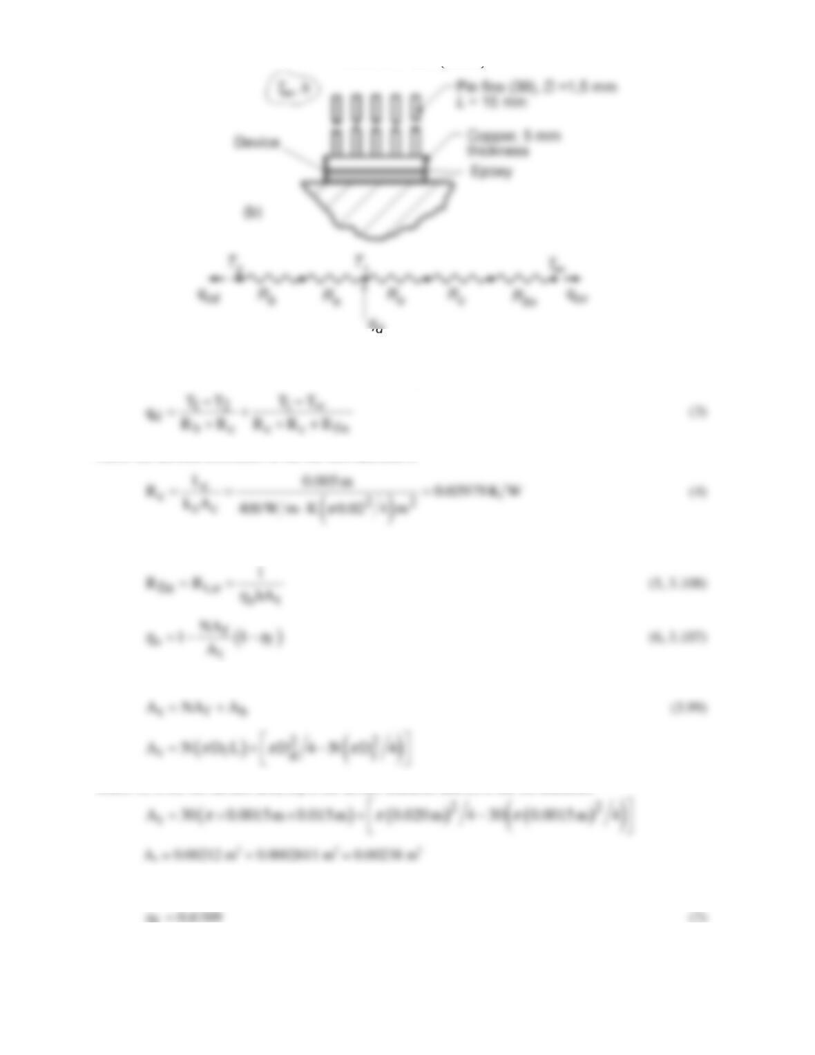
PROBLEM 4.31 (Cont.)
The thermal circuit for this system has two paths for the device power: to the block by conduction, qcd ,
and to the ambient air by conduction to the fin array, qcv,
where the thermal resistance of the fin base material is
and Rfin represents the thermal resistance of the fin array (see Section 3.6.5),
where the fin and prime surface area is
where Af is the fin surface area, Dd is the device diameter and Df is the fin diameter.
Using the IHT Model, Extended Surfaces, Performance Calculations, Rectangular Pin Fin, find the fin
efficiency as
f0.6769=
h
Continued…
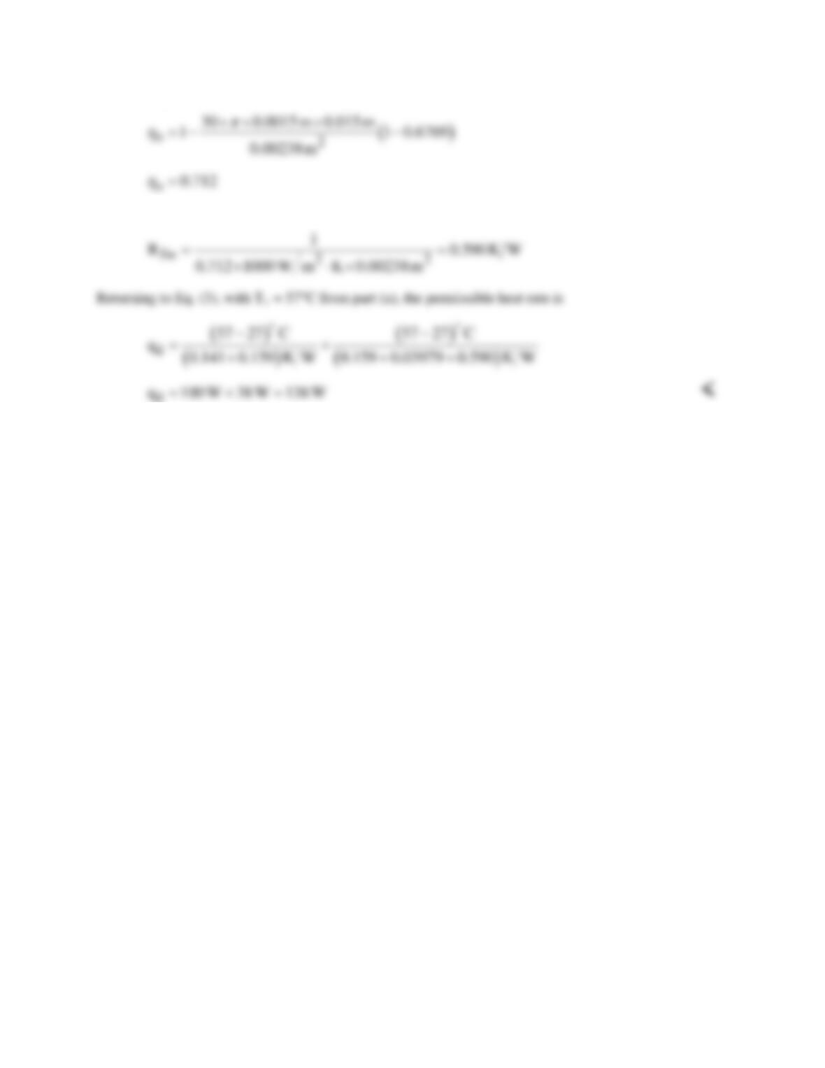
PROBLEM 4.31 (Cont.)
Substituting numerical values into Equation (6), find
and the fin array thermal resistance is
COMMENTS: In calculating the fin efficiency, hf, using the IHT Model it is not necessary to know the
base temperature as hf depends only upon geometric parameters, thermal conductivity and the convection
coefficient.
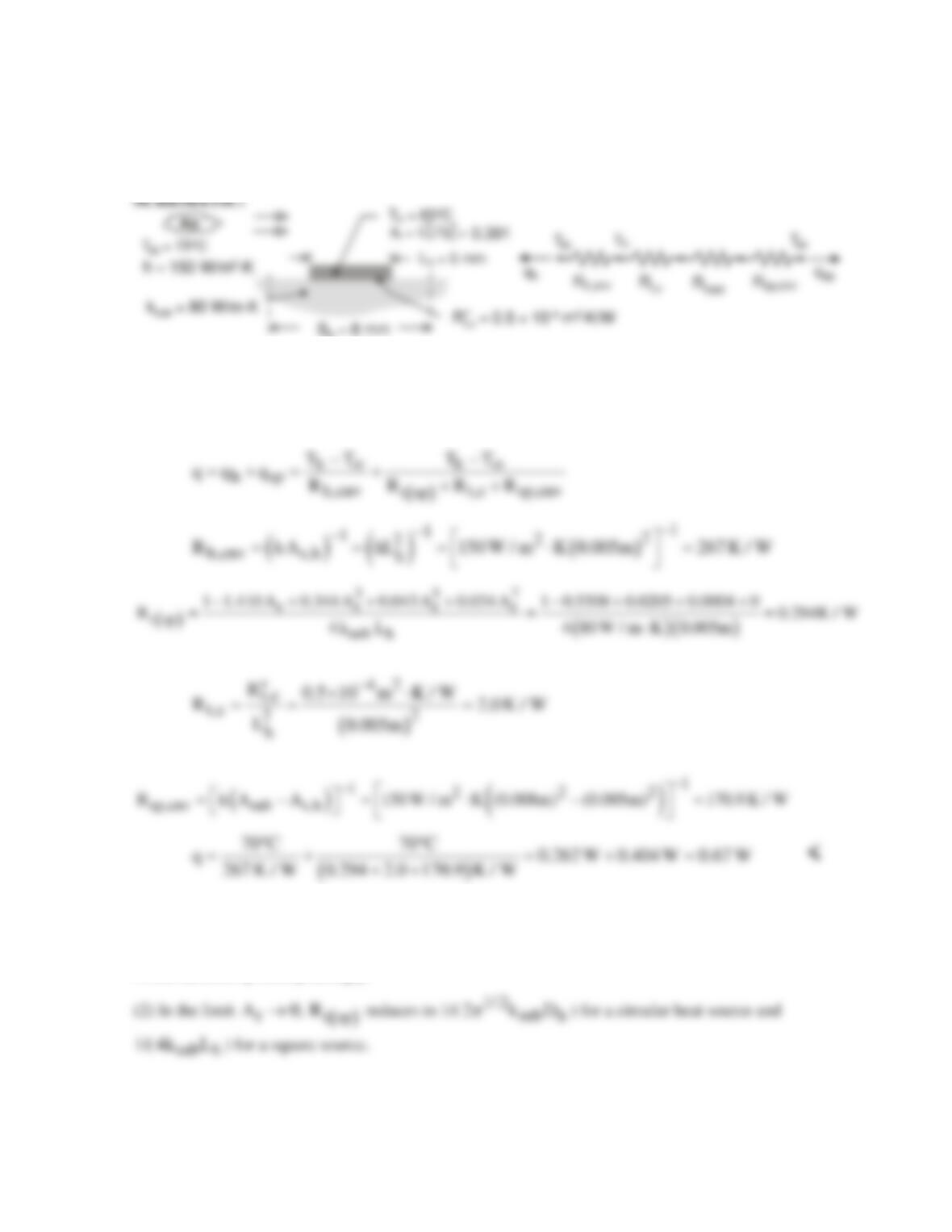
PROBLEM 4.32
KNOWN: Dimensions of chip array. Conductivity of substrate. Convection conditions. Contact
resistance. Expression for resistance of spreader plate. Maximum chip temperature.
FIND: Maximum chip heat rate.
h
ASSUMPTIONS: (1) Steady-state, (2) Constant thermal conductivity, (3) Negligible radiation, (4)
All heat transfer is by convection from the chip and the substrate surface (negligible heat transfer
from bottom or sides of substrate).
ANALYSIS: From the thermal circuit,
COMMENTS: (1) The thermal resistances of the substrate and the chip/substrate interface are much
less than the substrate convection resistance. Hence, the heat rate is increased almost in proportion to
the additional surface area afforded by the substrate. An increase in the spacing between chips (Sh)
would increase q correspondingly.
PROBLEM 4.33
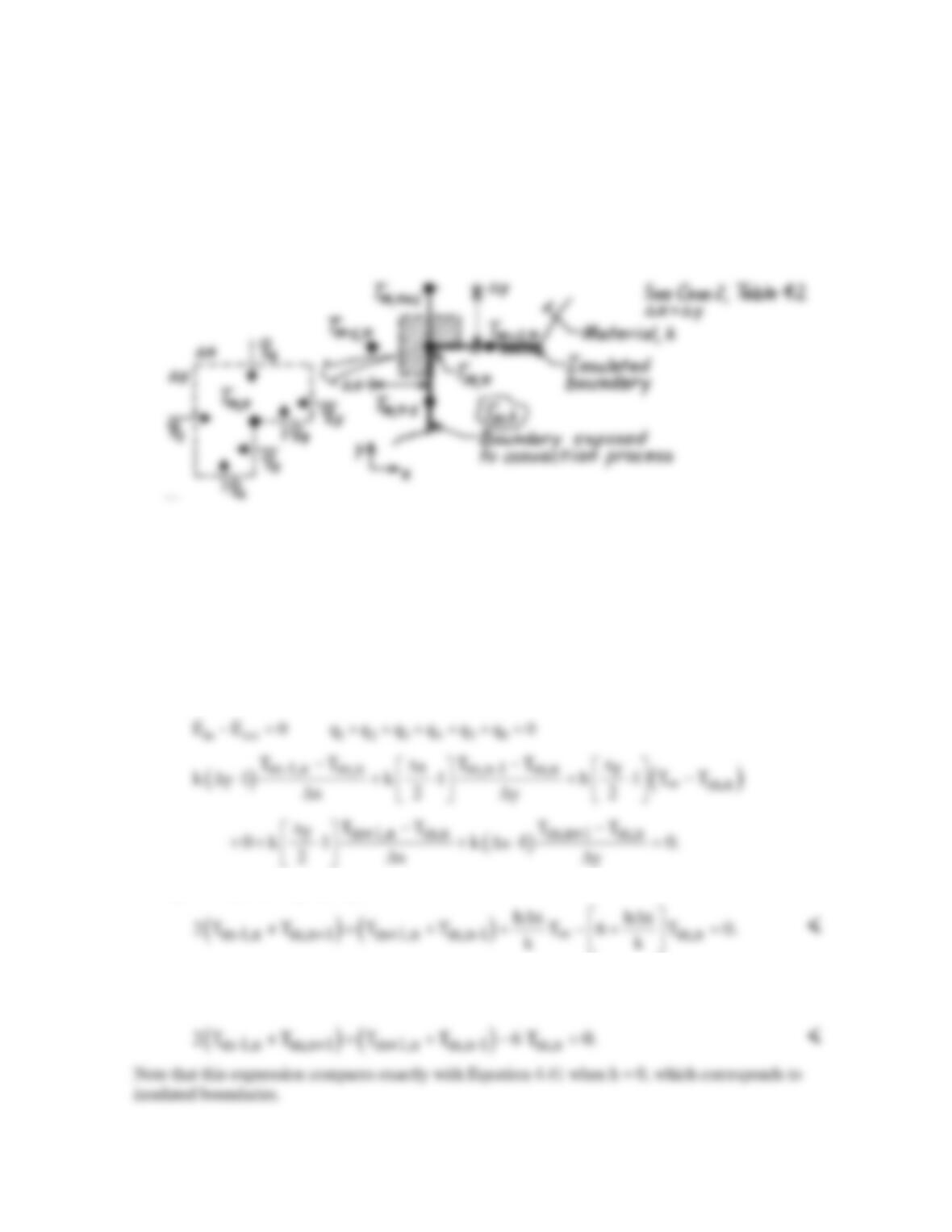
KNOWN: Internal corner of a two-dimensional system with prescribed convection boundary
conditions.
FIND: Finite–difference equations for these situations: (a) Horizontal boundary is perfectly insulated
and vertical boundary is subjected to a convection process (T∞,h), (b) Both boundaries are perfectly
insulated; compare result with Eq. 4.41.
SCHEMATIC:
ASSUMPTIONS: (1) Steady-state conditions, (2) Two-dimensional conduction, (3) Constant
properties, (4) No internal generation.
ANALYSIS: Consider the nodal network shown above and also as Case 2, Table 4.2. Having
defined the control volume – the shaded area of unit thickness normal to the page – next identify the
heat transfer processes. Finally, perform an energy balance wherein the processes are expressed using
appropriate rate equations.
(a) With the horizontal boundary insulated and the vertical boundary subjected to a convection
process, the energy balance results in the following finite–difference equation:
Letting ∆x = ∆y, and regrouping, find
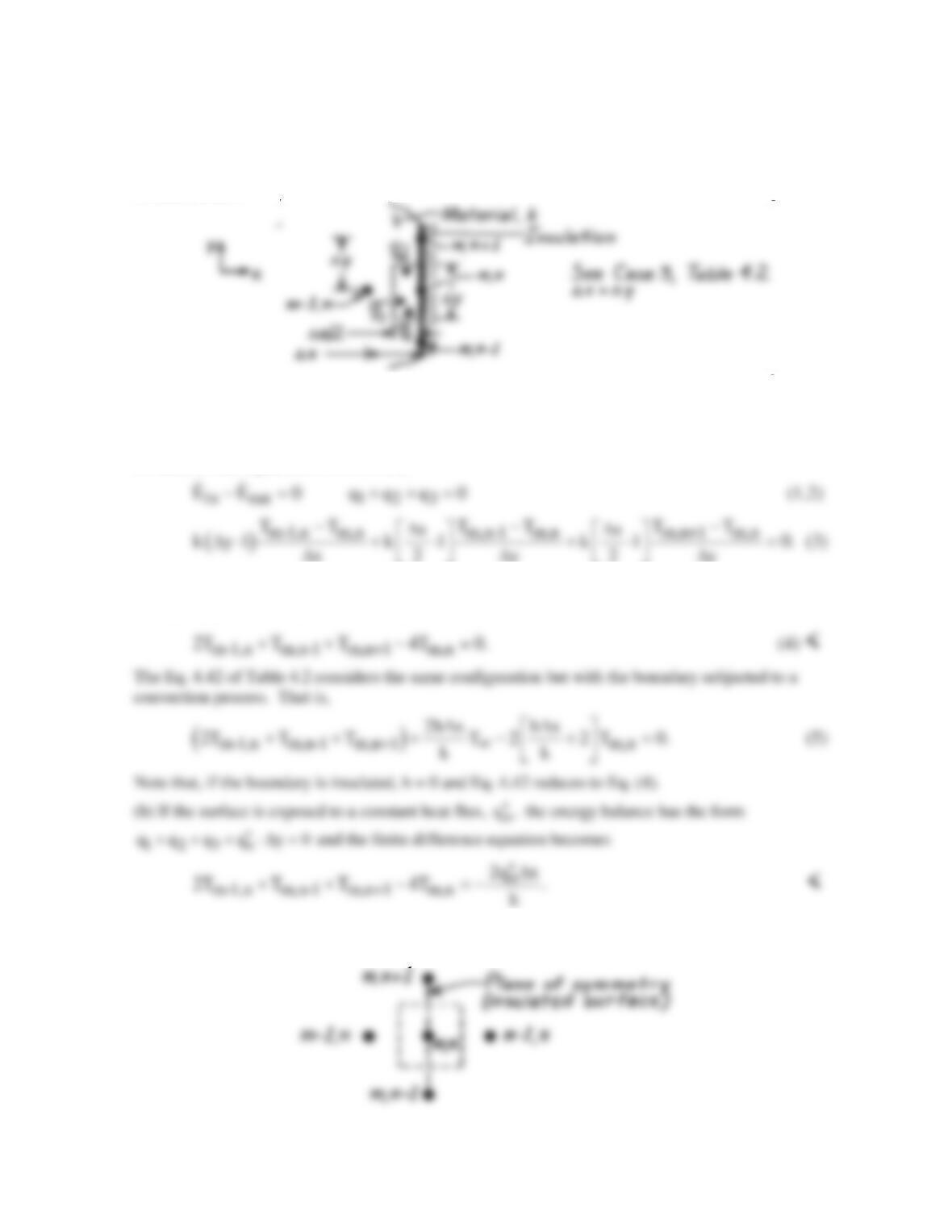
(b) With both boundaries insulated, the energy balance would have q3 = q4 = 0. The same result
would be obtained by letting h = 0 in the previous result. Hence,
PROBLEM 4.34
KNOWN: Plane surface of two–dimensional system.
FIND: The finite–difference equation for nodal point on this boundary when (a) insulated; compare
result with Eq. 4.42, and when (b) subjected to a constant heat flux.
SCHEMATIC:
ASSUMPTIONS: (1) Two–dimensional, steady-state conduction with no generation, (2) Constant
properties, (3) Boundary is adiabatic.
ANALYSIS: (a) Performing an energy balance on the control volume, (∆x/2)⋅∆y, and using the
conduction rate equation, it follows that
Note that there is no heat rate across the control volume surface at the insulated boundary.
Recognizing that ∆x =∆y, the above expression reduces to the form
COMMENTS: Equation (4) can be obtained by using the “interior node” finite-difference equation,
Eq. 4.29, where the insulated boundary is treated as a symmetry plane as shown below.
PROBLEM 4.35
KNOWN: Boundary conditions that change from specified heat flux to convection.
FIND: The finite difference equation for the node at the point where the boundary condition changes.
SCHEMATIC:
ASSUMPTIONS: (1) Two dimensional, steady-state conduction with no generation, (2) Constant
properties.
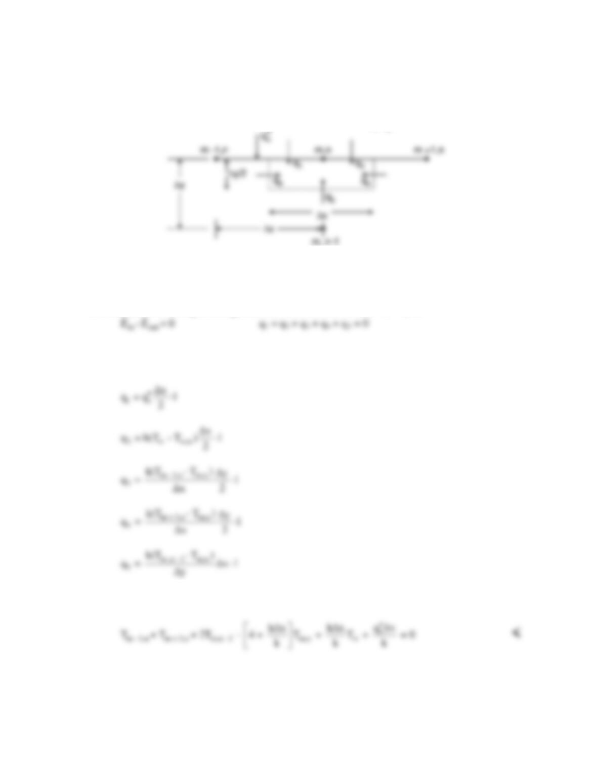
ANALYSIS: Performing an energy balance on the control volume ∆x • ∆y/2,
Expressing q1 in terms of the specified heat flux, q2 in terms of the known heat transfer coefficient
and environment temperature, and the remaining heat rates using the conduction rate equation,
Letting ∆x = ∆y, substituting these expressions into the energy balance, and rearranging yields
h, T∞
h, T∞
h, T∞
PROBLEM 4.36
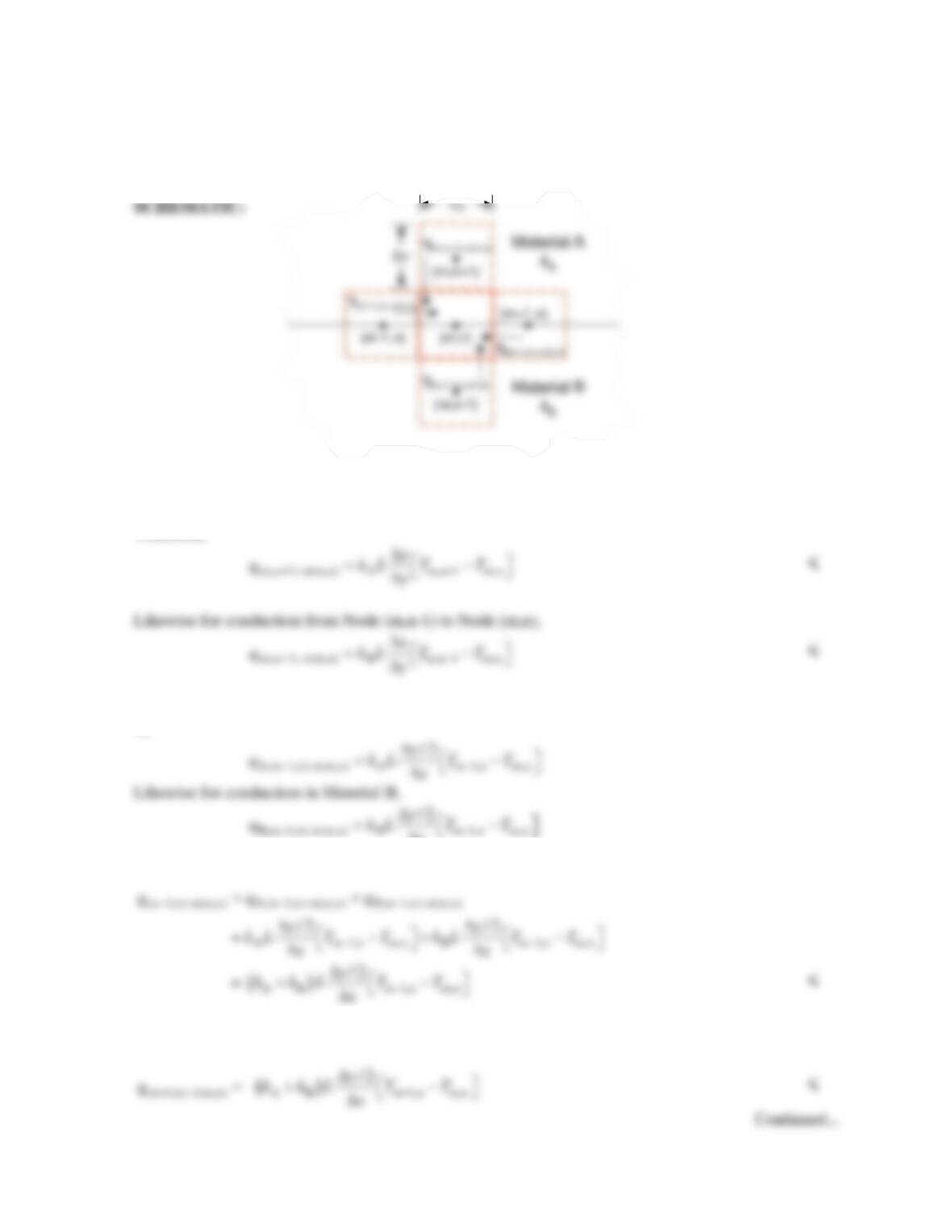
KNOWN: Control volume and nodal configuration in the vicinity of the interface between two
materials.
FIND: Expressions for control surface heat rates. Finite difference equation at node m,n.
ASSUMPTIONS: Steady–state, two–dimensional heat transfer, no heat generation, negligible contact
resistance.
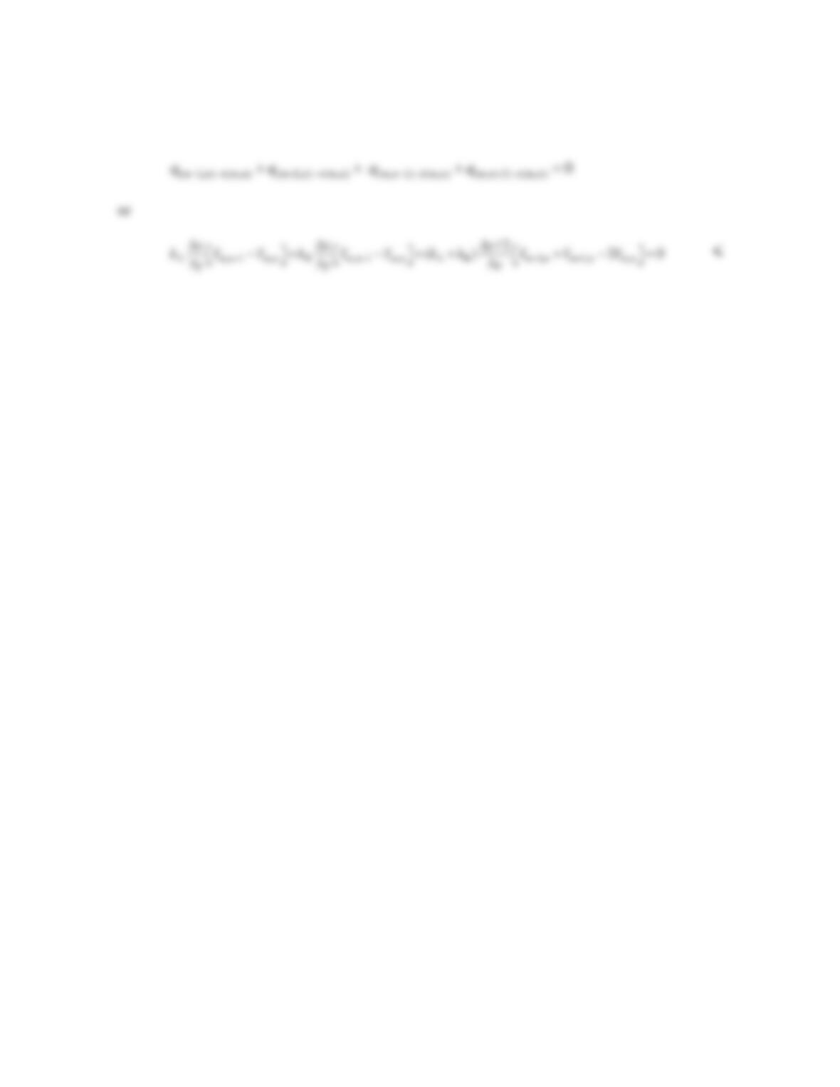
ANALYSIS: Conduction from Node (m,n+1) to Node (m,n) occurs exclusively in Material A.
Therefore,
Conduction from Node (m-1,n) to Node (m,n) occurs in both Material A and Material B. In Material
A,
x
∆
For both materials,
Similarly for conduction from Node (m+1,n) to (m,n),
PROBLEM 4.36 (Cont.)
An energy balance on node m,n yields
COMMENTS: How would you modify the analysis if the contact resistance is significant?
PROBLEM 4.37
KNOWN: Conduction in a one-dimensional (radial) cylindrical coordinate system with volumetric
generation.
FIND: Finite–difference equation for (a) Interior node, m, and (b) Surface node, n, with convection.
ASSUMPTIONS: (1) Steady-state, one-dimensional (radial) conduction in cylindrical coordinates,
(2) Constant properties.
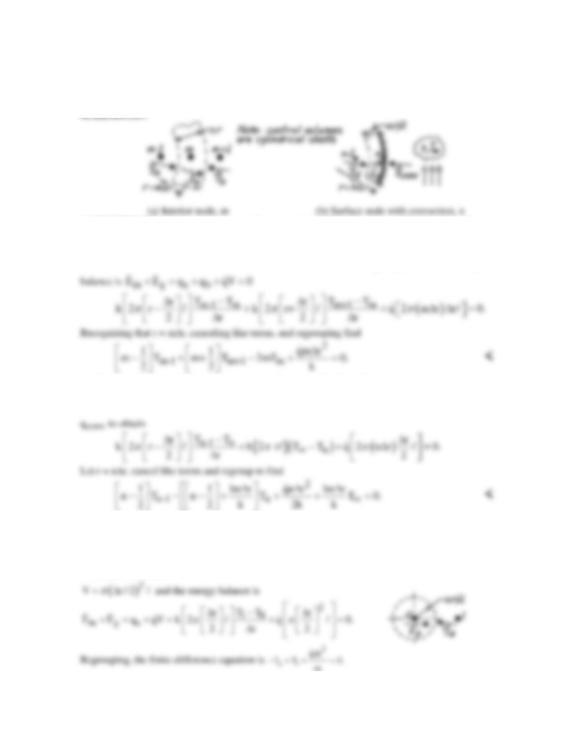
ANALYSIS: (a) The network has nodes spaced at equal ∆r increments with m = 0 at the center;
hence, r = m∆r (or n∆r). The control volume is
( )
V 2 r r 2 mr r .
ππ
= ⋅∆⋅ = ∆ ∆⋅
The energy
(b) The control volume for the surface node is
( )
V 2 r r/2 .
π
= ⋅∆ ⋅
The energy balance is
in g d conv
E E q q qV=0.+=+ +
Use Fourier’s law to express qd and Newton’s law of cooling for
COMMENTS: (1) Note that when m or n becomes very large compared to ½, the finite-difference
equation becomes independent of m or n. Then the cylindrical system approximates a rectangular
one.
(2) The finite-difference equation for the center node (m = 0) needs to be treated as a special case.
The control volume is
4k
PROBLEM 4.38
KNOWN: Two-dimensional cylindrical configuration with prescribed radial (∆r) and angular (∆φ)
spacings of nodes.
FIND: Finite–difference equations for nodes 2, 3 and 1.
SCHEMATIC:
ASSUMPTIONS: (1) Steady-state conditions, (2) Two-dimensional conduction in cylindrical
coordinates (r,φ), (3) Constant properties.
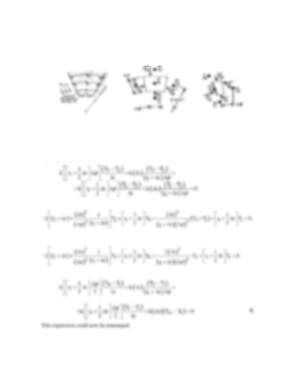
ANALYSIS: The method of solution is to define the appropriate control volume for each node, to
identify relevant processes and then to perform an energy balance.
(a) Node 2. This is an interior node with control volume as shown above. The energy balance is
in a b c d
E q q q q 0.
′′′′
=+++ =
Using Fourier’s law for each process, find
Canceling terms and regrouping yields,
(b) Node 3. The adiabatic surface behaves as a symmetry surface. We can utilize the result of Part
(a) to write the finite–difference equation by inspection as
(c) Node 1. The energy balance is
abcd
q q q q 0.
′′′′
+++ =
Substituting,
PROBLEM 4.39
KNOWN: Heat generation and thermal boundary conditions of bus bar. Finite-difference grid.
FIND: Finite–difference equations for selected nodes.
ASSUMPTIONS: (1) Steady-state conditions, (2) Two-dimensional conduction, (3) Constant
properties.
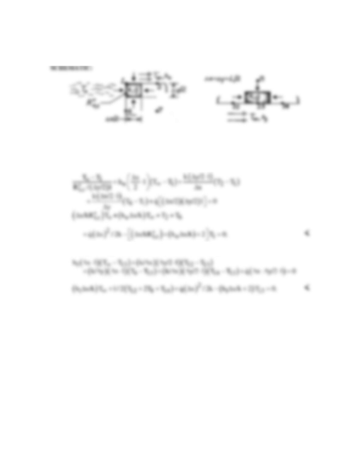
ANALYSIS: (a) Performing an energy balance on the control volume, (∆x/2)(∆y/2)⋅1, find the FDE
for node 1,
(b) Performing an energy balance on the control volume, (∆x)(∆y/2)⋅1, find the FDE for node 13,
COMMENTS: For fixed To and T∞, the relative amounts of heat transfer to the air and heat sink
are determined by the values of h and
t,c
R.
′′
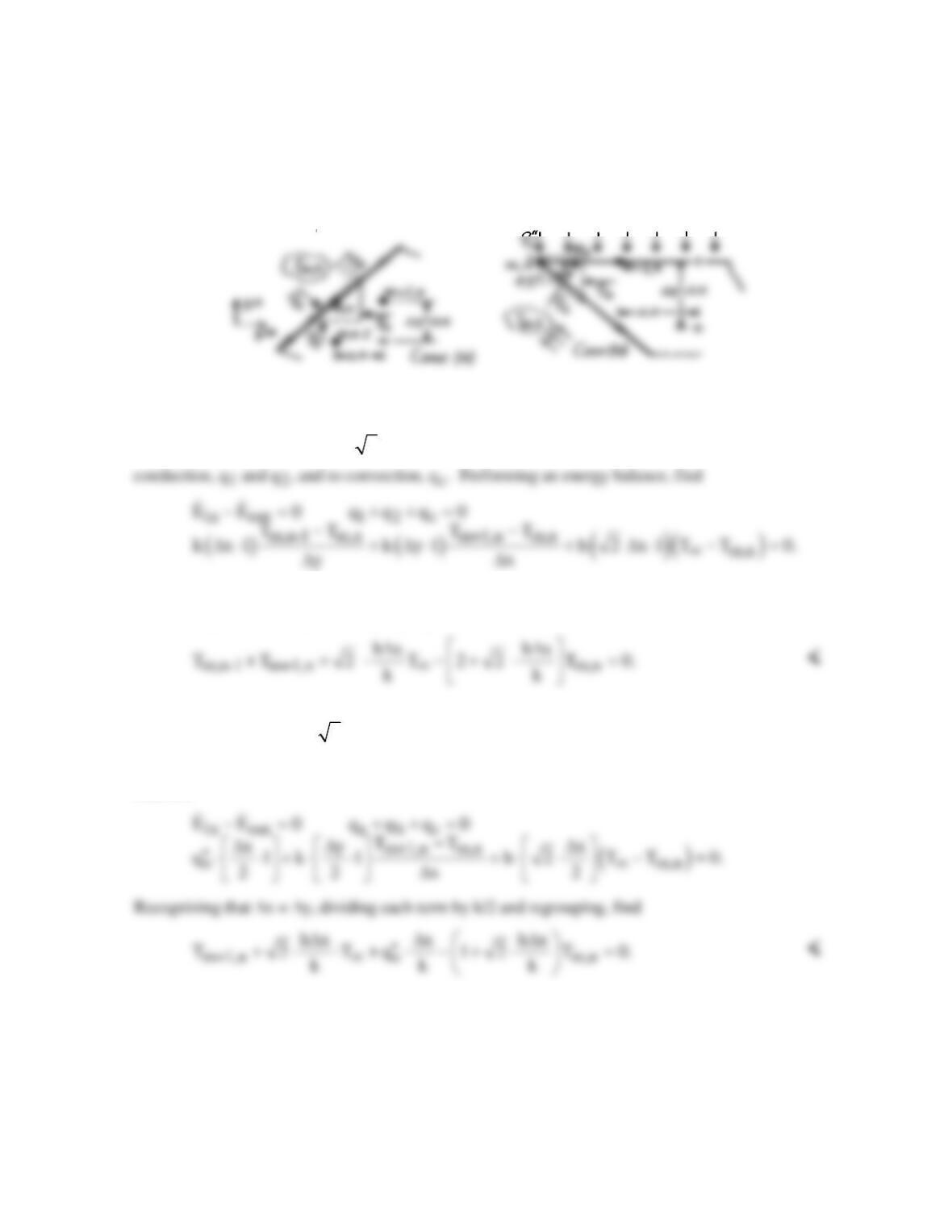
PROBLEM 4.40
KNOWN: Nodal point configurations corresponding to a diagonal surface boundary subjected to a
convection process and to the tip of a machine tool subjected to constant heat flux and convection
cooling.
FIND: Finite–difference equations for the node m,n in the two situations shown.
SCHEMATIC:
ASSUMPTIONS: (1) Steady-state, 2–D conduction, (2) Constant properties.
ANALYSIS: (a) The control volume about node m,n has triangular shape with sides ∆x and ∆y while
the diagonal (surface) length is
2
∆x. The heat rates associated with the control volume are due to
Note that we have considered the solid to have unit depth normal to the page. Recognizing that ∆x =
∆y, dividing each term by k and regrouping, find
(b) The control volume about node m,n has triangular shape with sides ∆x/2 and ∆y/2 while the lower
diagonal surface length is
( )
2 x/2 .∆
The heat rates associated with the control volume are due to
the constant heat flux, qa, to conduction, qb, and to the convection process, qc. Perform an energy
balance,
COMMENTS: Note the appearance of the term h∆x/k in both results, which is a dimensionless
parameter (the Biot number) characterizing the relative effects of convection and conduction.
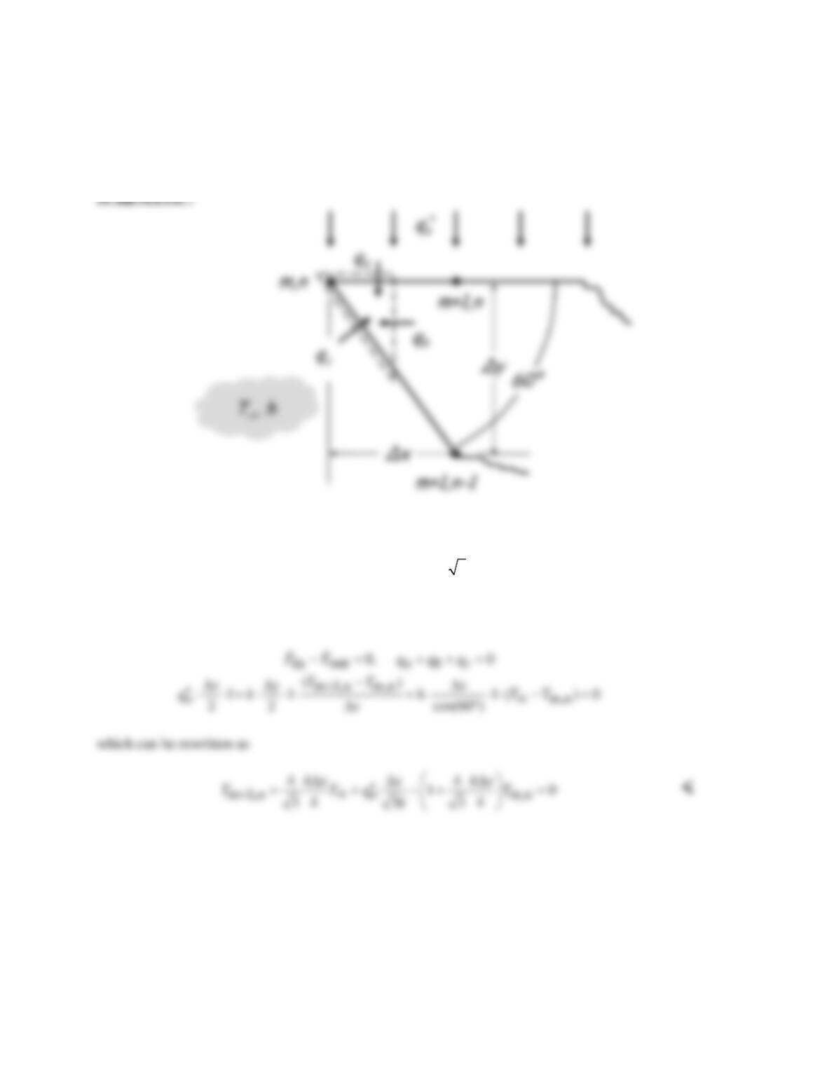
PROBLEM 4.41
KNOWN: Cutting tool with tip angle of 60°. Upper surface exposed to constant heat flux, diagonal
surface exposed to convection with known environment temperature and heat transfer coefficient.
FIND: Derive nodal finite difference equation for node (m,n).
ASSUMPTIONS: (1) Steady–state conditions. (2) Uniform properties.
ANALYSIS: It is convenient to choose ∆y/∆x = tan60° =
3,
so that the control volume about node m,n
has a triangular shape as shown in the schematic. The heat rates associated with the control volume are
due to the constant heat flux on the upper surface, qa, to conduction from the right, qb, and to the
convection process, qc. Performing an energy balance,
COMMENTS: Note the appearance of the term h∆x/k, which is a dimensionless parameter (the Biot
number) characterizing the relative effects of convection and conduction.
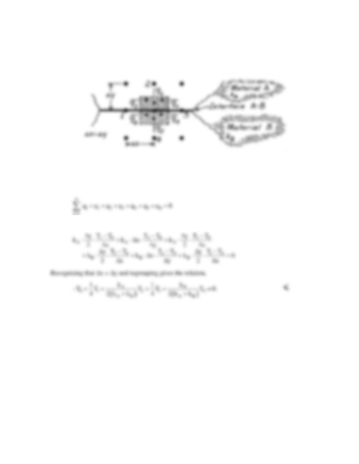
PROBLEM 4.42
KNOWN: Nodal point on boundary between two materials.
FIND: Finite–difference equation for steady–state conditions.
SCHEMATIC:
ASSUMPTIONS: (1) Steady-state conditions, (2) Two-dimensional conduction, (3) Constant
properties, (4) No internal heat generation, (5) Negligible thermal contact resistance at interface.
ANALYSIS: The control volume is defined about nodal point 0 as shown above. The conservation
of energy requirement has the form
i1
=
since all heat rates are shown as into the CV. Each heat rate can be written using Fourier’s law,
COMMENTS: Note that when kA = kB, the result agrees with Equation 4.29 which is appropriate
for an interior node in a medium of fixed thermal conductivity.
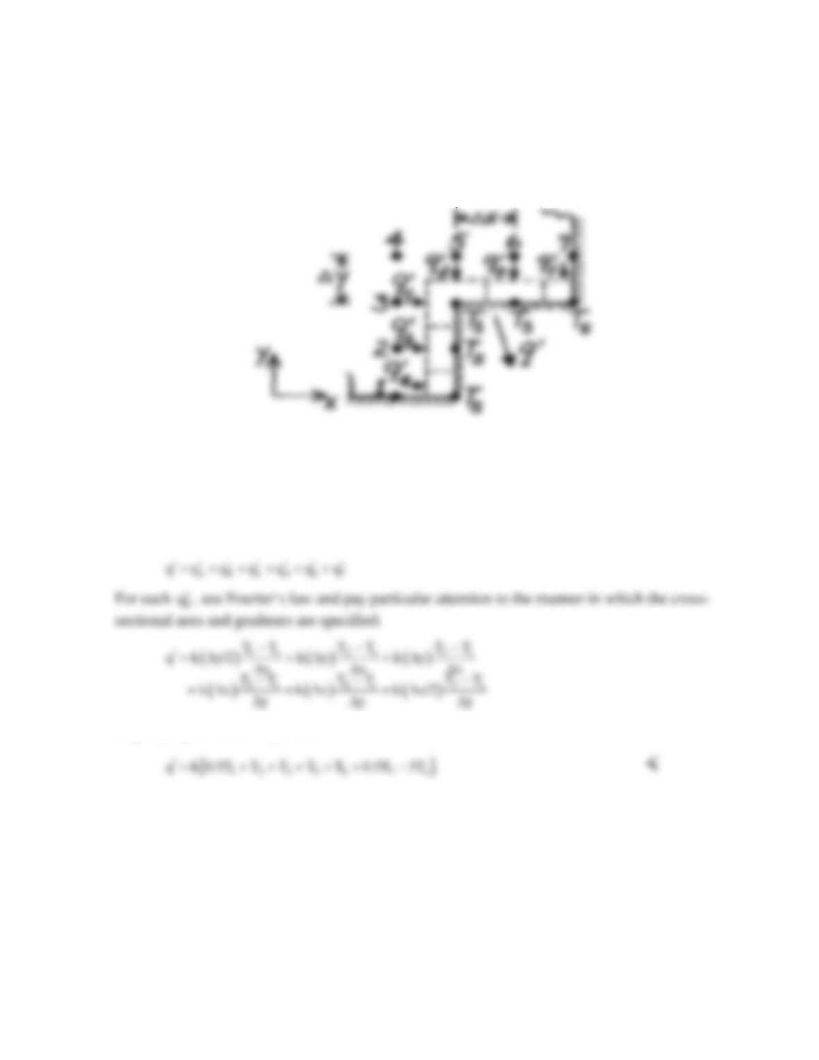
PROBLEM 4.43
KNOWN: Two–dimensional grid for a system with no internal volumetric generation.
FIND: Expression for heat rate per unit length normal to page crossing the isothermal
boundary.
SCHEMATIC:
ASSUMPTIONS: (1) Steady-state conditions, (2) Two-dimensional heat transfer, (3)
Constant properties.
ANALYSIS: Identify the surface nodes (Ts) and draw control volumes about these nodes.
Since there is no heat transfer in the direction parallel to the isothermal surfaces, the heat rate
out of the constant temperature surface boundary is
Regrouping with ∆x = ∆y, find
COMMENTS: Looking at the corner node, it is important to recognize the areas associated
with
cd
q and q
′′
(∆y and ∆x, respectively).
PROBLEM 4.44
KNOWN: One-dimensional fin of uniform cross section insulated at one end with prescribed base
temperature, convection process on surface, and thermal conductivity.
FIND: Finite–difference equation for these nodes: (a) Interior node, m and (b) Node at end of fin, n,
where x = L.
ASSUMPTIONS: (1) Steady-state conditions, (2) One-dimensional conduction.
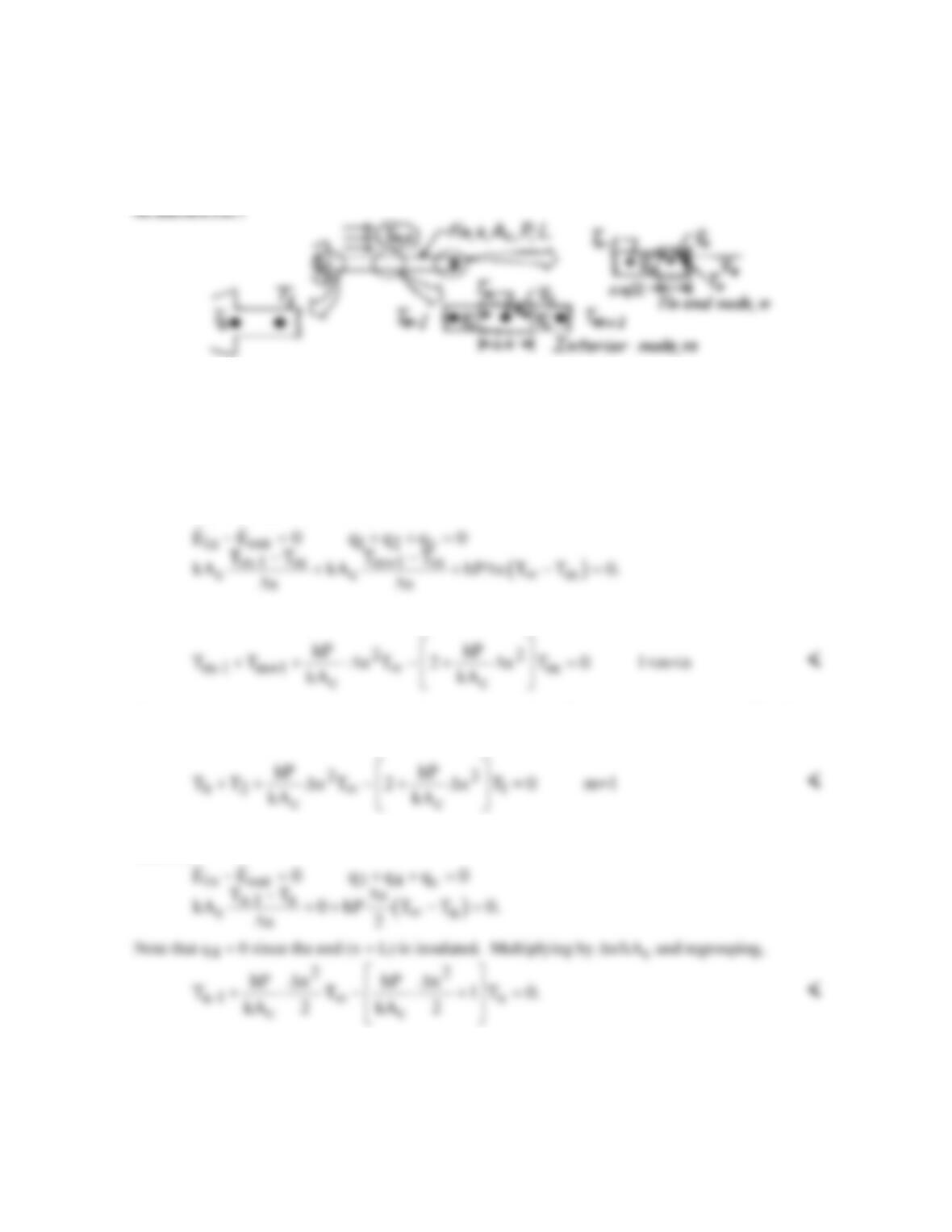
ANALYSIS: (a) The control volume about node m is shown in the schematic; the node spacing and
control volume length in the x direction are both ∆x. The uniform cross-sectional area and fin
perimeter are Ac and P, respectively. The heat transfer process on the control surfaces, q1 and q2,
represent conduction while qc is the convection heat transfer rate between the fin and ambient fluid.
Performing an energy balance, find
Multiply the expression by ∆x/kAc and regroup to obtain
Considering now the special node m = 1, then the m-1 node is Tb, the base temperature. The finite–
difference equation would be
(b) The control volume of length ∆x/2 about node n is shown in the schematic. Performing an energy
balance,
COMMENTS: The value of ∆x will be determined by the selection of n; that is, ∆x = L/n. Note that
the grouping, hP/kAc, appears in the finite–difference and differential forms of the energy balance.
PROBLEM 4.45
KNOWN: Two-dimensional network with prescribed nodal temperatures and thermal conductivity
of the material.
FIND: Heat rate per unit length normal to page,
q.
′
SCHEMATIC:
7 154.21
ASSUMPTIONS: (1) Steady-state conditions, (2) Two-dimensional heat transfer, (3) No internal
volumetric generation, (4) Constant properties.
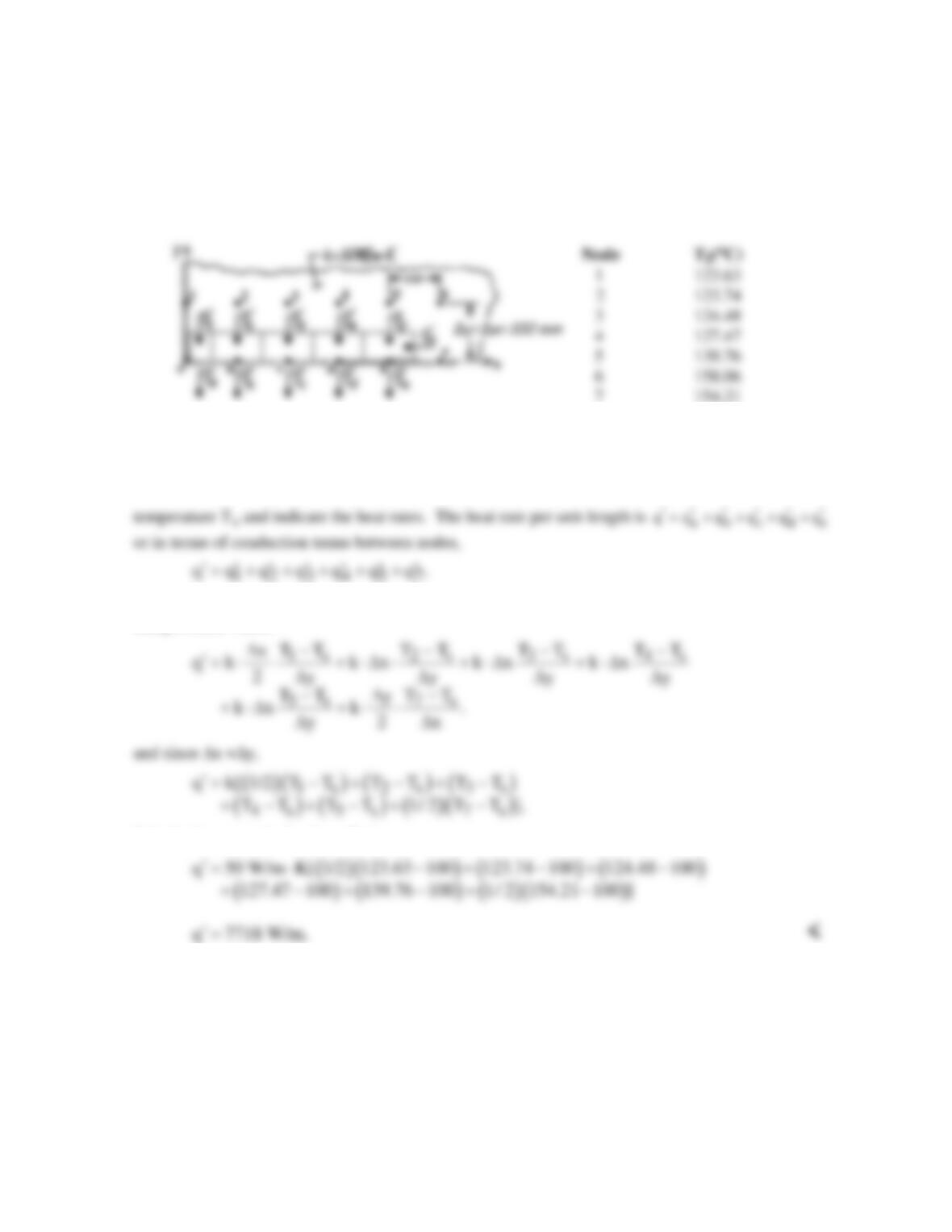
ANALYSIS: Construct control volumes around the nodes on the surface maintained at the uniform
Each of these rates can be written in terms of nodal temperatures and control volume dimensions
using Fourier’s law,
Substituting numerical values, find
COMMENTS: For nodes a through d, there is no heat transfer into the control volumes in the x-
direction. Look carefully at the energy balance for node e,
e 57
q q q,
′′′
= +
and how
57
q and q
′′
are
evaluated.
PROBLEM 4.46
KNOWN: Nodal temperatures from a steady–state, finite–difference analysis for a one-eighth
symmetrical section of a square channel.
FIND: (a) Beginning with properly defined control volumes, derive the finite-difference equations for
nodes 2, 4 and 7, and determine T2, T4 and T7, and (b) Heat transfer loss per unit length from the
channel,
q′
.
ASSUMPTIONS: (1) Steady-state conditions, (2) Two-dimensional conduction, (3) No internal
volumetric generation, (4) Constant properties.
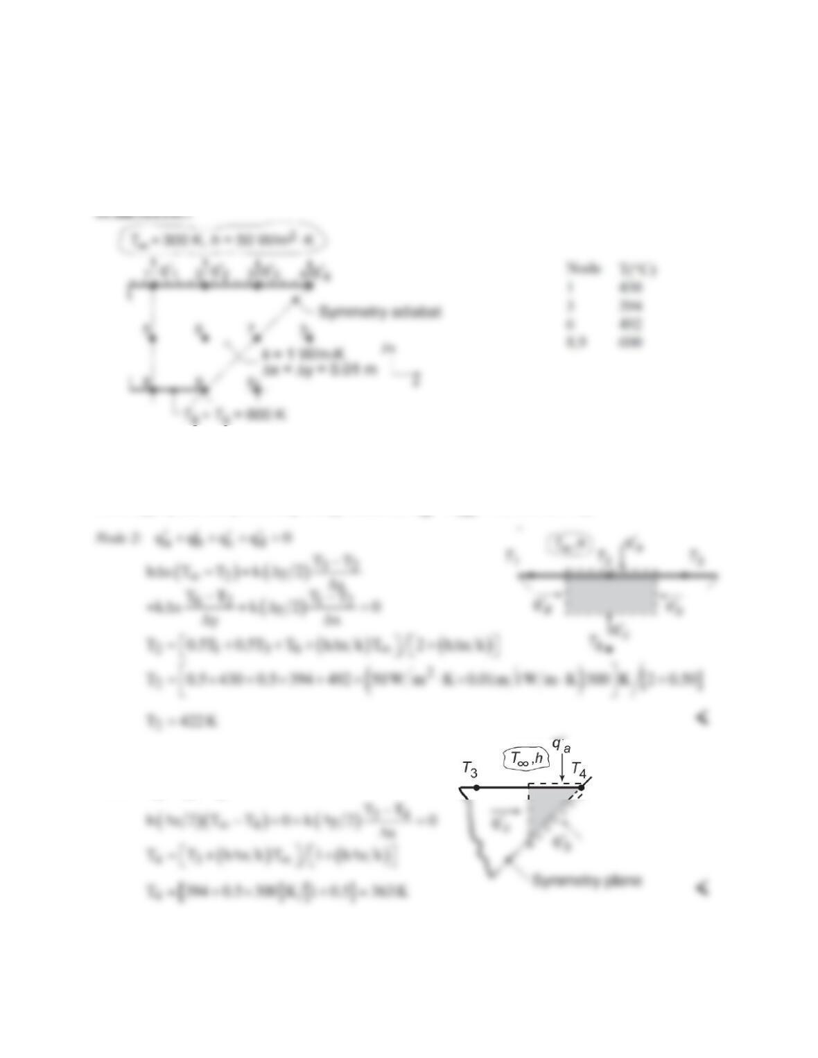
ANALYSIS: (a) Define control volumes about the nodes 2, 4, and 7, taking advantage of symmetry
where appropriate and performing energy balances,
in out
EE 0−=
, with ∆x = ∆y,
Node 4:
abc
qqq0
′′′
++=
Continued…
PROBLEM 4.46 (Cont.)
Node 7: From the first schematic, recognizing that the diagonal is a symmetry adiabat, we can treat node
7 as an interior node, hence
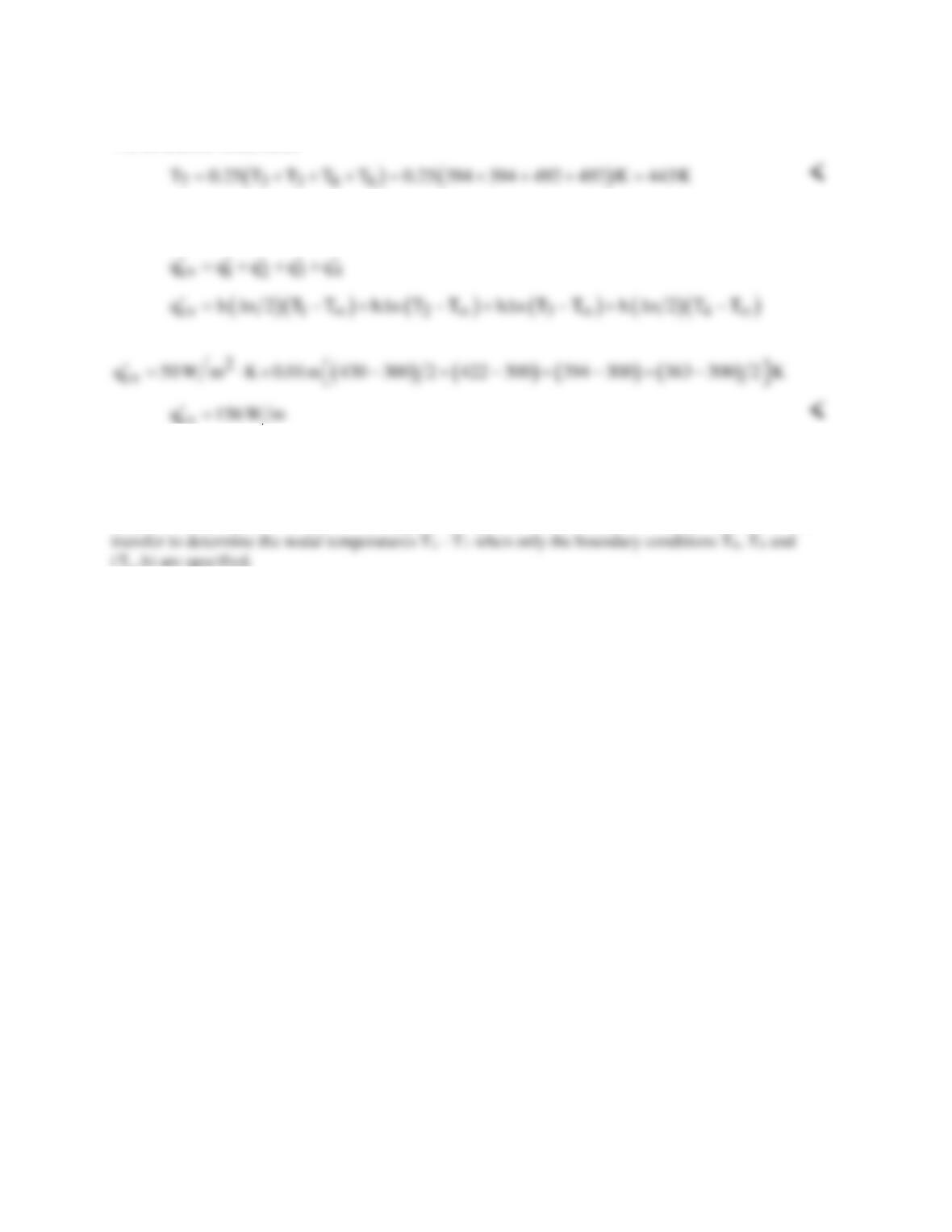
(b) The heat transfer loss from the upper surface can be expressed as the sum of the convection rates
from each node as illustrated in the first schematic,
cv
COMMENTS: (1) Always look for symmetry conditions which can greatly simplify the writing of the
nodal equation as was the case for Node 7.
(2) Consider using the IHT Tool, Finite-Difference Equations, for Steady-State, Two-Dimensional heat