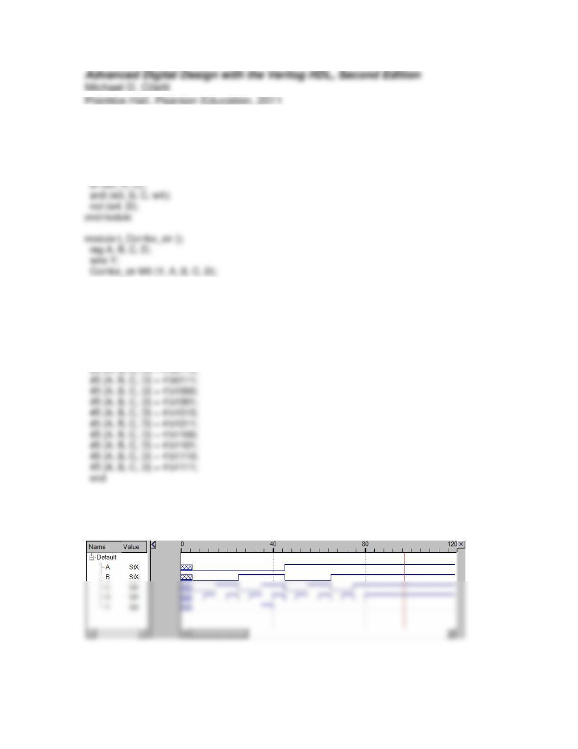
Problem 4-1
module Combo_str (output Y, input A, B, C, D);
and (Y, w1, w3);
not (w1, w2);
initial begin
#5 {A, B, C, D} = 4’b0000;
#5 {A, B, C, D} = 4’b0001;
#5 {A, B, C, D} = 4’b0010;
#5 {A, B, C, D} = 4’b0011;
#5 {A, B, C, D} = 4’b0100;
#5 {A, B, C, D} = 4’b0101;
initial begin #500 $finish; end
//initial begin $monitor ($time,,”%h %b“, {A, B, C, D}, Y); end
endmodule
Problem 4-2
module Combo_UDP (output Y, input A, B, C, D);
Combo_prim M0 (Y, A, B, C, D);
endmodule
initial begin
#5 {A, B, C, D} = 4’b0000;
#5 {A, B, C, D} = 4’b0001;
#5 {A, B, C, D} = 4’b0010;
#5 {A, B, C, D} = 4’b0011;
#5 {A, B, C, D} = 4’b0100;
#5 {A, B, C, D} = 4’b0101;
#5 {A, B, C, D} = 4’b0110;
#5 {A, B, C, D} = 4’b0111;
initial begin #500 $finish; end
//initial begin $monitor ($time,,”%h %b“, {A, B, C, D}, Y); end
endmodule
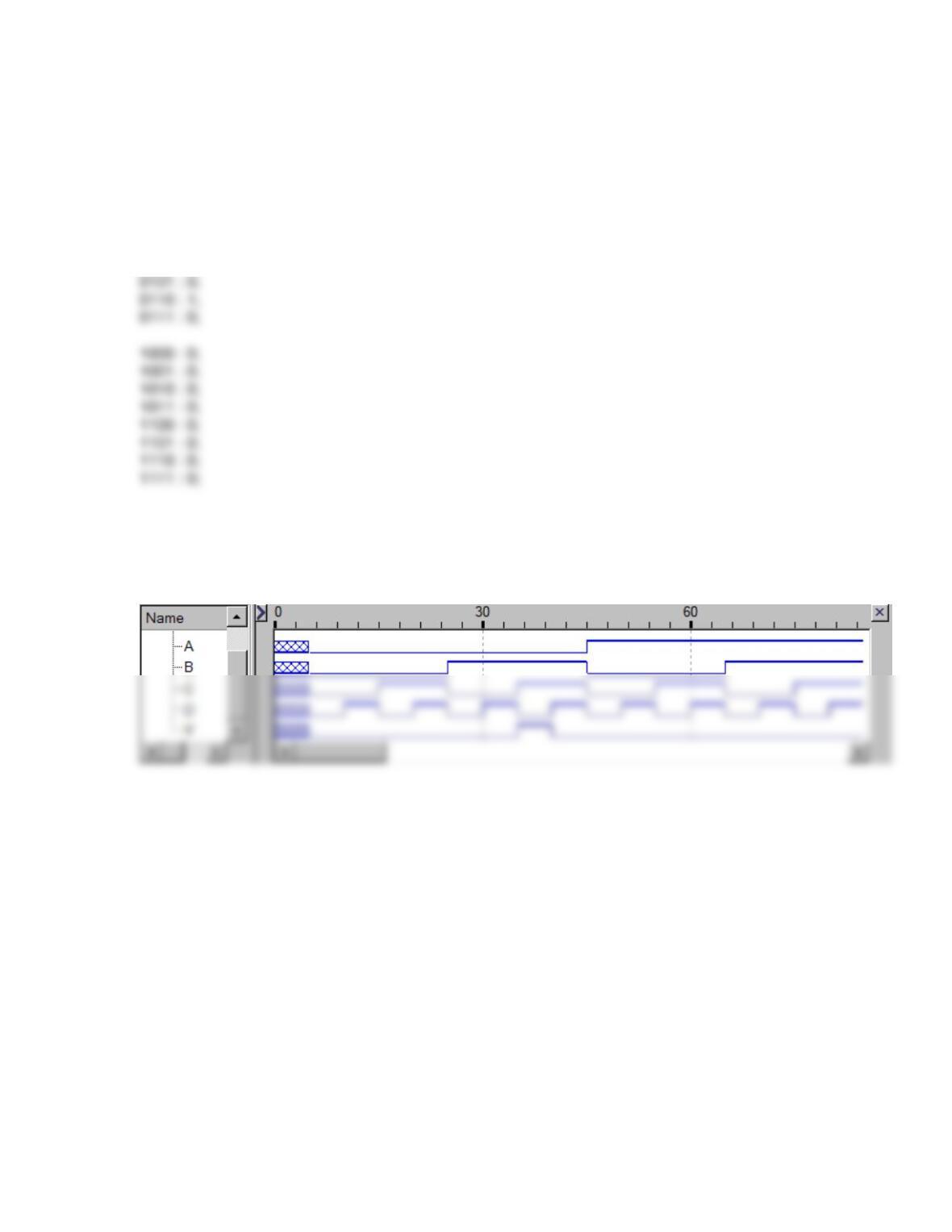
primitive Combo_prim (output Y, input A, B, C, D);
table
0000 : 0;
0001 : 0;
0010 : 0;
0011 : 0;
0100 : 0;
endtable
endprimitive
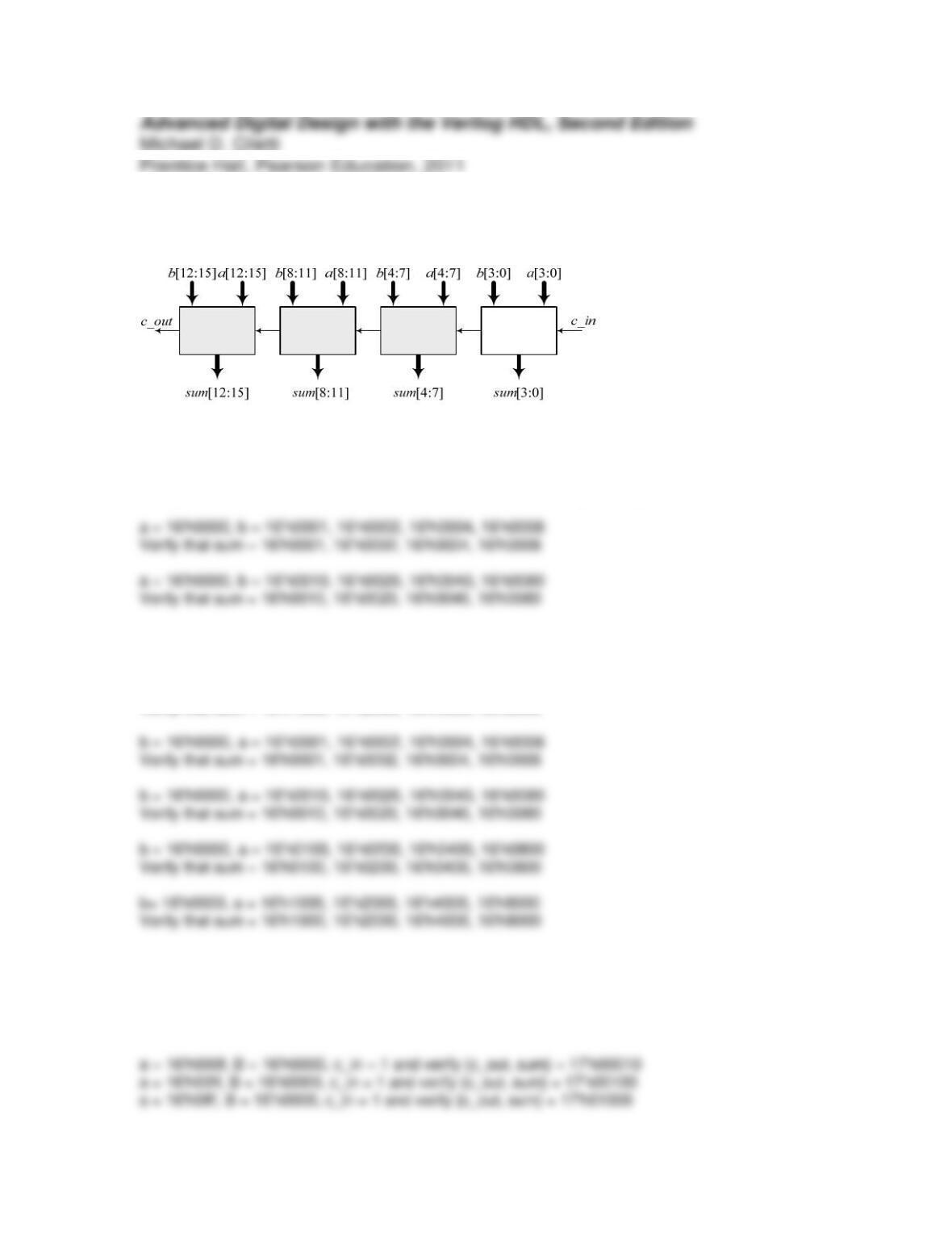
Problem 4-3
The connectivity of the 16-bit adder will be verified by the following tests:
Verify that each data bus to each 4-bit unit is connected correctly, with c_in = 0.
a = 16’h0000, b = 16’h0100, 16’h0200, 16’h0400, 16’h0800
Verify that sum = 16’h0100, 16’h0200, 16’h0400, 16’h0800
a = 16’h0000, b = 16’h1000, 16’h2000, 16’h4000, 16’h8000
Verify that sum = 16’h1000, 16’h2000, 16’h4000, 16’h8000
Verify that the c_in bit propagates through the carry chain correctly.
a = 16’hfff, b = 16’h0000, toggle c_in = 0 to c_in = 1
Verify that {c_out, sum} toggles from 17’h0ffff to 17’h1ffff
#10 a = 16’h0000, b = 16’h0010;
#10 b = 16’h0020;
#10 b = 16’h0040;
#10 b = 16’h0080;
//Verify that sum = 16’h0010, 16’h0020, 16’h0040, 16’h0080
#10 a = 16’h0000, b = 16’h0100;
#10 b = 16’h0200;
#10 b = 16’h0400;
#10 b = 16’h0800;
//Verify that sum = 16’h0100, 16’h0200, 16’h0400, 16’h0800
#10 b = 16’h0000, a = 16’h0010;
#10 a = 16’h0020;
#10 a = 16’h0040;
#10 a = 16’h0080;
//Verify that sum = 16’h0010, 16’h0020, 16’h0040, 16’h0080
#10 b = 16’h0000, a = 16’h0100;
#10 a = 16’h0200;
#10 a = 16’h0400;
#10 a = 16’h0800;
//Verify that sum = 16’h0100, 16’h0200, 16’h0400, 16’h0800

Problem 4-4
Parallel version
The alternative below creates a excess three output from a parallel input word.
This solution uses a single continuous assignment statement; an alternative (structural)
model could use half and full adders to implement the addition.
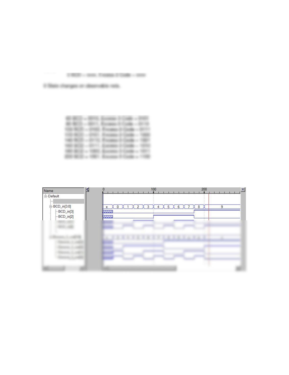
module encoder (output [3:0] Excess_3_out, input [3:0] BCD_in);
initial
$monitor($time,,”BCD = %b, Excess-3 Code = %b”, BCD_in, Excess_3_out);
initial begin
#500 $finish; //Simulation Time Out
end
initial begin //Simulation Test Pattern
#20 BCD_in = 4’b0000;
#20 BCD_in = 4’b0001;
#20 BCD_in = 4’b0010;
#20 BCD_in = 4’b0011;
t_encoder
3 total devices.
Linking …
9 nets total: 17 saved and 0 monitored.
68 registers total: 68 saved.
Done.
Simulation stopped at the end of time 0.
Ready: sim
20 BCD = 0000, Excess-3 Code = 0011
40 BCD = 0001, Excess-3 Code = 0100
62 State changes on observable nets.
Simulation stopped at the end of time 500.
Serial Version, modified flip-flop:
module Prob_4_4 (output B_out, input B_in, clk, reset);
// See Fig. 3-22
nand (y1, q0, q1, q2);
nand (y2, q0, q2_b, B_in_b);
nand (y3, q0_b, q1_b, B_in);
primitive d_prim1_mod (output reg q_out, input reset, clock, data);
table
// reset clk data state q_out/next_state
0 ? ? : ? : 0; // Asynch reset
1 ? ? : ? : -; // Asynch reset
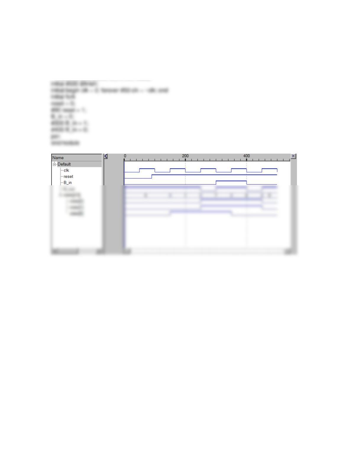
module test_Prob_4_4 ();
wire B_out;
reg B_in, clk, reset;
wire[2:0] state = {M0.q2,M0.q1,M0.q0};
Prob_4_4 M0( B_out, B_in, clk, reset);
Problem 4-5
d_prim1
q_out
clock
data
Test plan:
Verify that data (0, 1, x) is clocked on the postive edge of the clock
primitive d_prim1 (output reg q_out, input clock, data);
table
// clk data state q_out/next_state
(01) 0 : ? : 0 ; // Rising clock edge
(01) 1 : ? : 1 ;
(0?) 1 : 1 : 1 ;
initial #500 $finish;
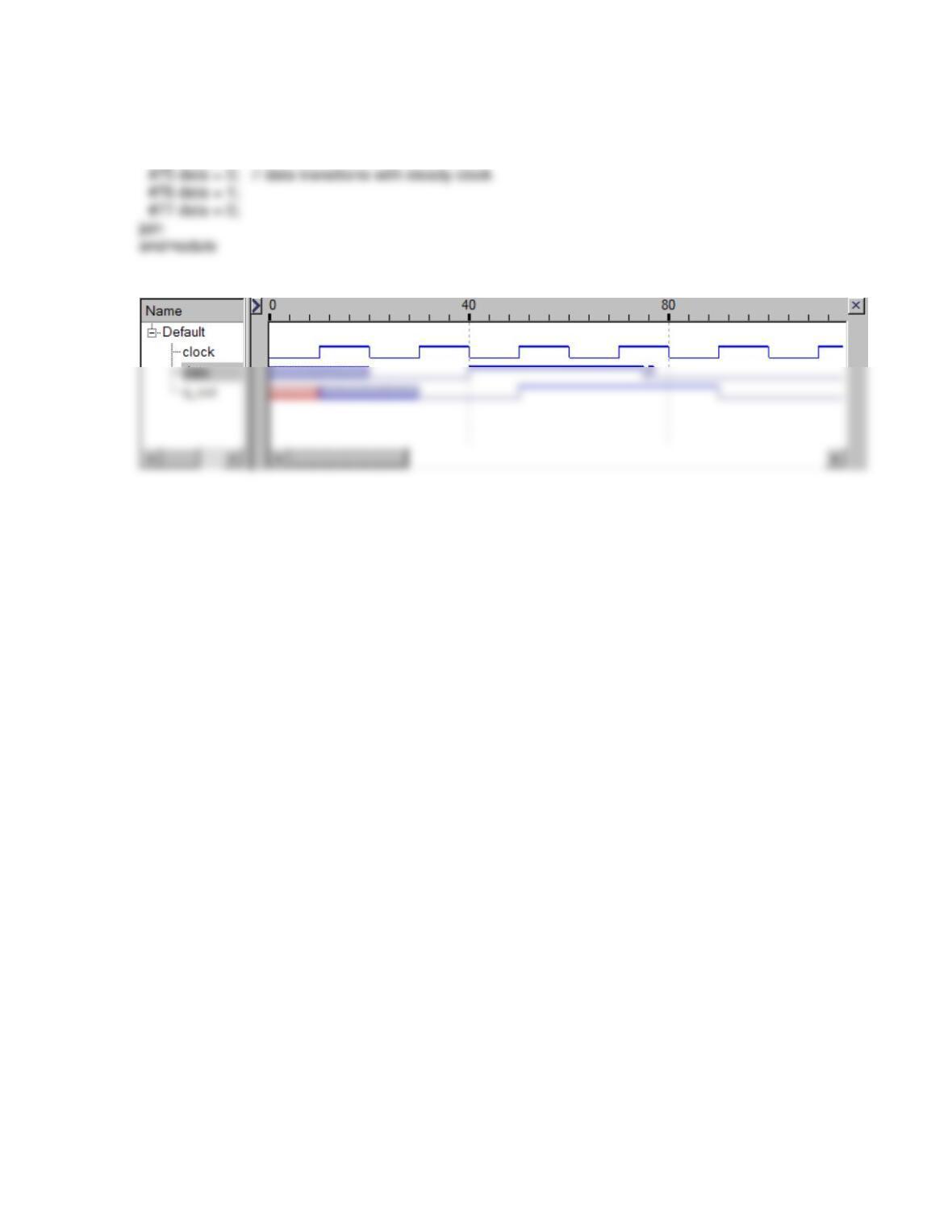
initial begin clock = 0; forever #10 clock = ~clock; end
initial fork
#20 data = 0;
#40 data = 1;
Problem 4-7
module Problem_4_7 (output Y1, Y2, input A, B, C, D);
not (A_not, A);
not (B_not, B);
not (C_not, C);
not (D_not, D);
endmodule
module t_Problem_4_7();
reg A, B, C, D;
wire Y1, Y2;
Problem_4_7 M0 (Y1, Y2, A, B, C, D);
initial begin
#5 {A, B, C, D} = 4’b0000;
#5 {A, B, C, D} = 4’b0001;
#5 {A, B, C, D} = 4’b0010;
#5 {A, B, C, D} = 4’b0011;
//initial begin $monitor ($time,,”%h %b“, {A, B, C, D}, Y); end
endmodule
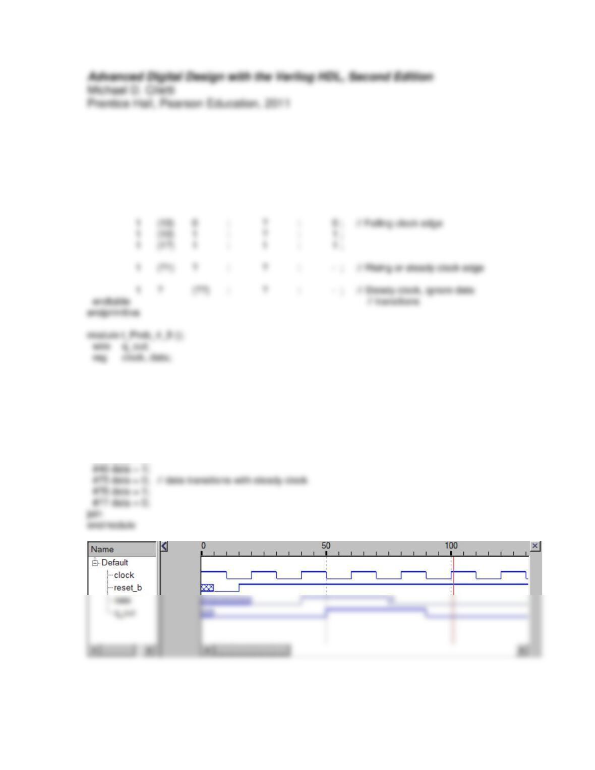
Problem 4-8
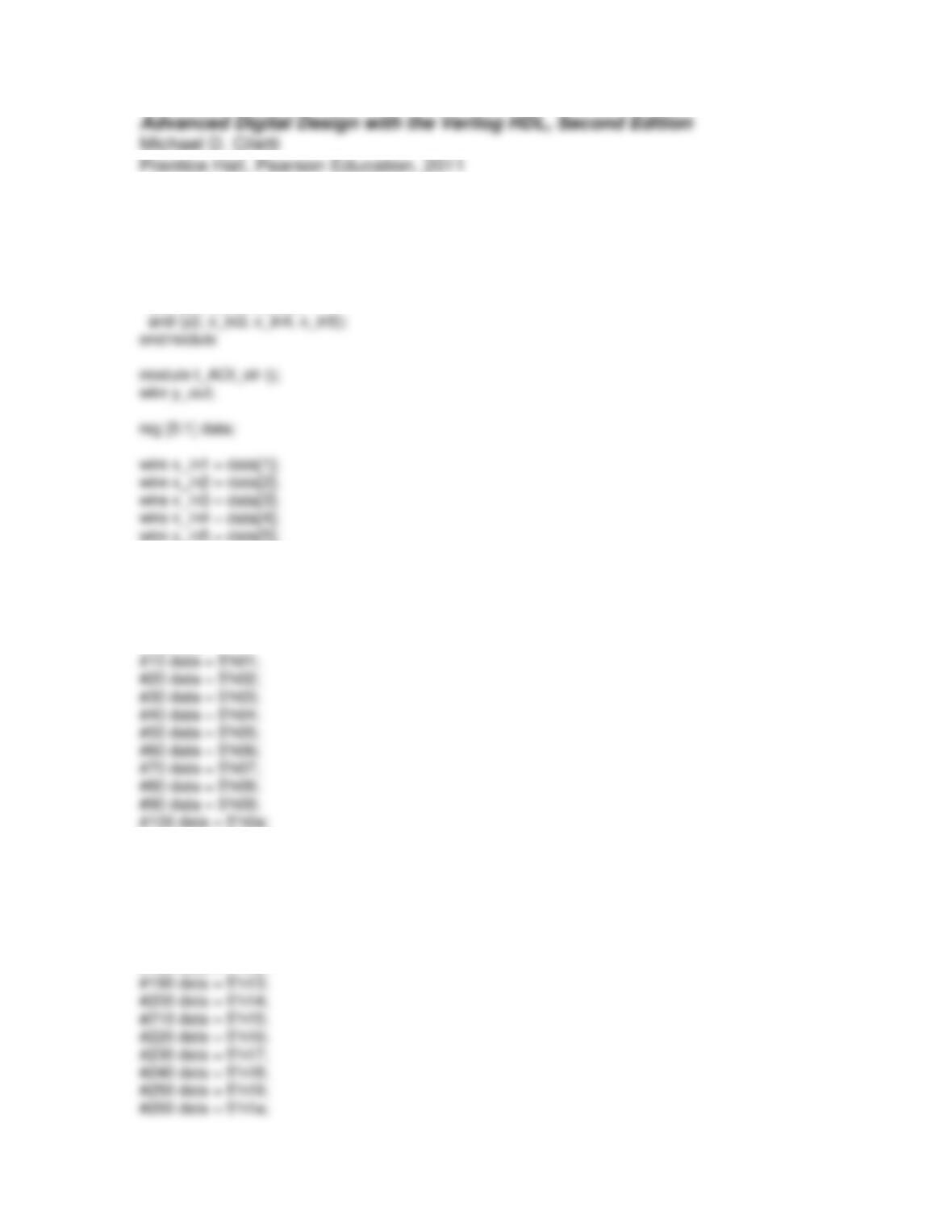
primitive Prob_4_8 (output reg q_out, input reset_b, clock, data);
table
// reset_b clk data state q_out/next_state
0 ? ? : ? : 0; // Asynch reset
1 ? ? : ? : -; // Asynch reset
Prob_4_8 M0 (q_out, reset_b, clock, data);
initial #500 $finish;
initial begin clock = 1; forever #10 clock = ~clock; end
initial fork
#5 reset_b = 0;
#15 reset_b = 1;
#20 data = 0;
Problem 4-9
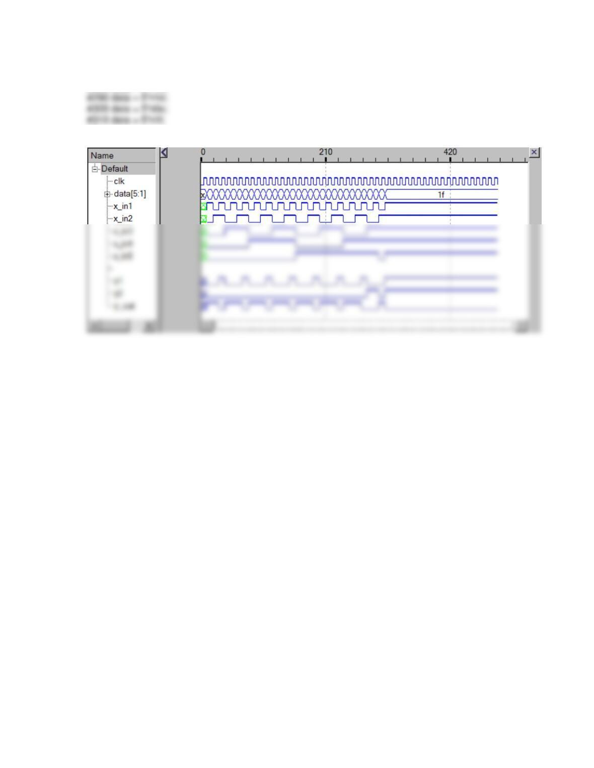
module AOI_str (output y_out, input x_in1, x_in2, x_in3, x_in4, x_in5);
wire y1, y2;
nor (y_out, y1, y2);
and (y1, x_in1, x_in2);
reg clk;
AOI_str M0 (y_out, x_in1, x_in2, x_in3, x_in4, x_in5);
initial #500 $finish;
initial begin clk = 0; forever #5 clk = ~clk; end
initial fork
#110 data = 5’h0b;
#120 data = 5’h0c;
#130 data = 5’h0d;
#140 data = 5’h0e;
#150 data = 5’h0f;
#160 data = 5’h10;
#170 data = 5’h11;
#180 data = 5’h12;
#270 data = 5’h1b;
#280 data = 5’h1c;
join
endmodule
Problem 4-10
module t_latch_rp ();
reg enable, data;
wire q_out;
latch_rp M0 (q_out, enable, data);
initial #200 $finish;