PROBLEM 4.14
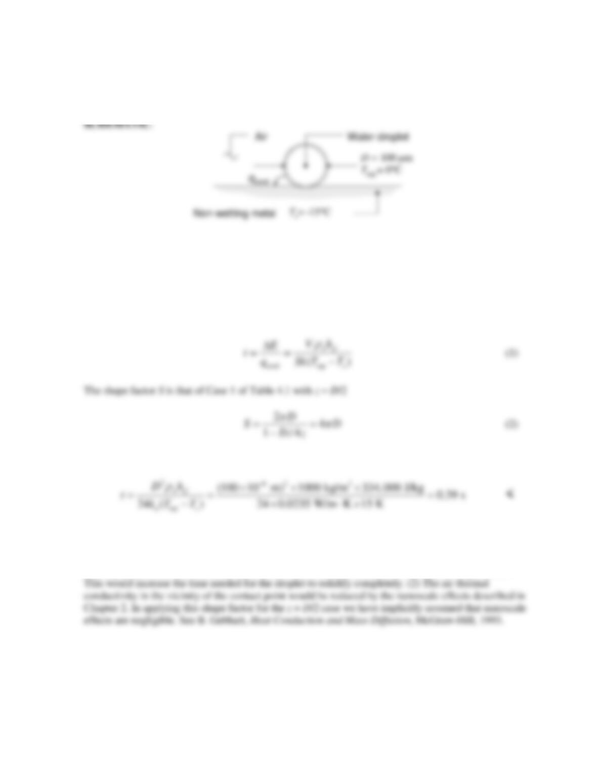
KNOWN: Dimensions and temperature of water droplet.
FIND: Time for droplet to freeze completely.
ASSUMPTIONS: (1) Constant properties, (2) Negligible convection and radiation, (3) Isothermal
water particle, (4) Semi-infinite medium.
PROPERTIES: Table A.4, Air (265 K): ka = 0.0235 W/m⋅K. Table A.6, Liquid water (273 K):
ρ
w =
1000 kg/m3.
ANALYSIS: An energy balance on the droplet yields
Combining Equations (1) and (2) with the expression for the droplet volume V = πD3/6 yields
COMMENTS: (1) Solidification might initiate in the lower region of the droplet. The ice that forms
would pose an additional conduction resistance between the cold metal surface and the liquid water.
PROBLEM 4.15
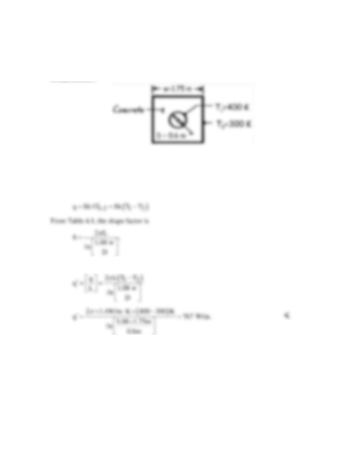
KNOWN: Dimensions and boundary temperatures of a steam pipe embedded in a concrete
casing.
FIND: Heat loss per unit length.
SCHEMATIC:
ASSUMPTIONS: (1) Steady–state conditions, (2) Negligible steam side convection
resistance, pipe wall resistance and contact resistance (T1 = 400K), (3) Constant properties.
PROPERTIES: Table A-3, Concrete (300K): k = 1.4 W/m⋅K.
ANALYSIS: The heat rate can be expressed as
Hence,
COMMENTS: Having neglected the steam side convection resistance, the pipe wall
resistance, and the contact resistance, the foregoing result overestimates the actual heat loss.
PROBLEM 4.16
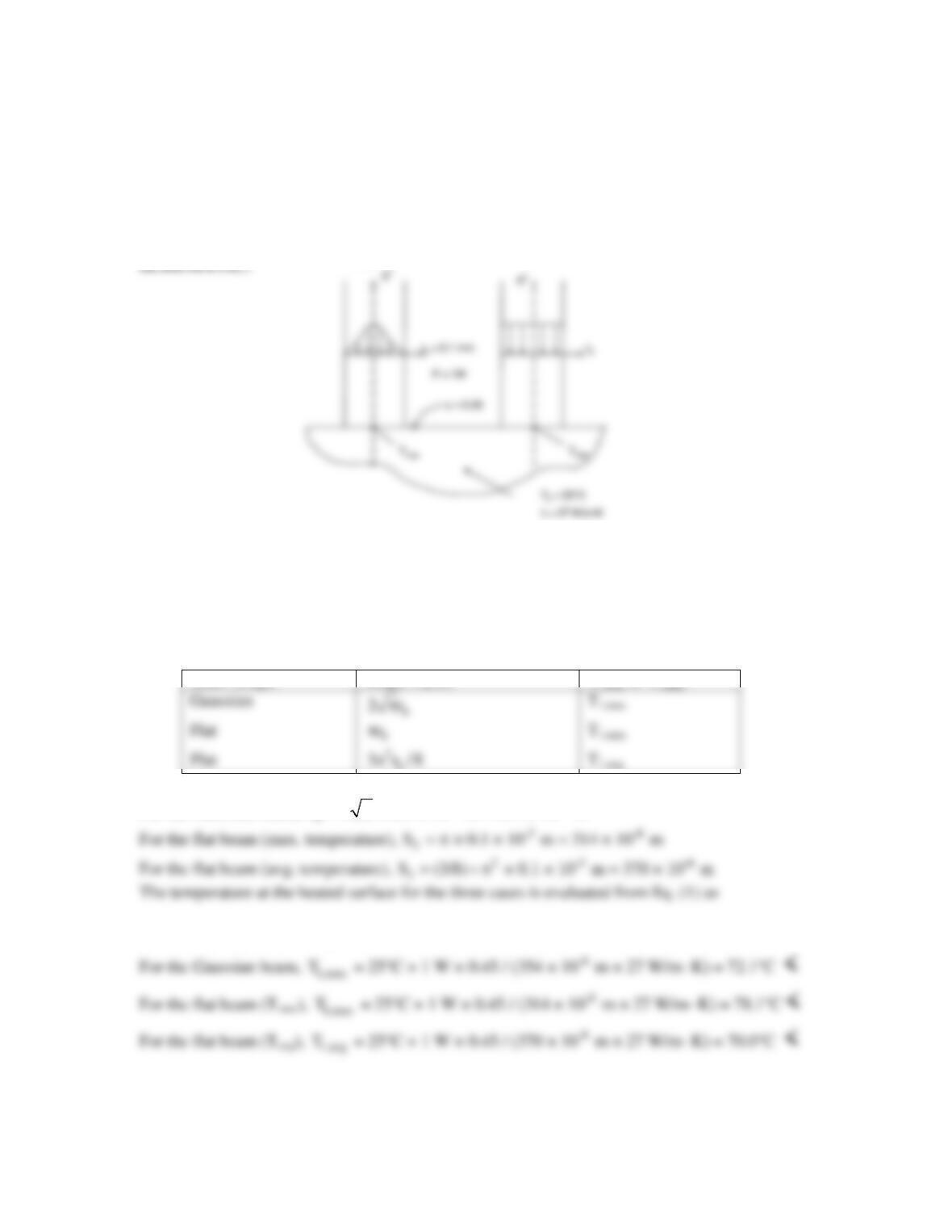
KNOWN: Power, size and shape of laser beam. Material properties.
FIND: Maximum surface temperature for a Gaussian beam, maximum temperature for a flat
beam, and average temperature for a flat beam.
ASSUMPTIONS: (1) Steady-state conditions, (2) Constant properties, (3) Semi-infinite medium,
(4) Negligible heat loss from the top surface.
ANALYSIS: The shape factor is defined in Eq. 4.20 and is q = Sk∆T1-2 (1)
From the problem statement and Section 4.3, the shape factors for the three cases are:
Beam Shape
Shape Factor
T1,avg or T1,max
b
For the Gaussian beam,
-3 -6
S = 2 π × 0.1 × 10 m = 354 × 10 m
12 2
T = T + q/Sk = T + P /Skα
COMMENTS: (1) The maximum temperature occurs at r = 0 for all cases. For the flat beam, the
maximum temperature exceeds the average temperature by 78.1 – 70.0 = 8.1 degrees Celsius.
Flat
Gaussian
Flat
Gaussian
PROBLEM 4.17
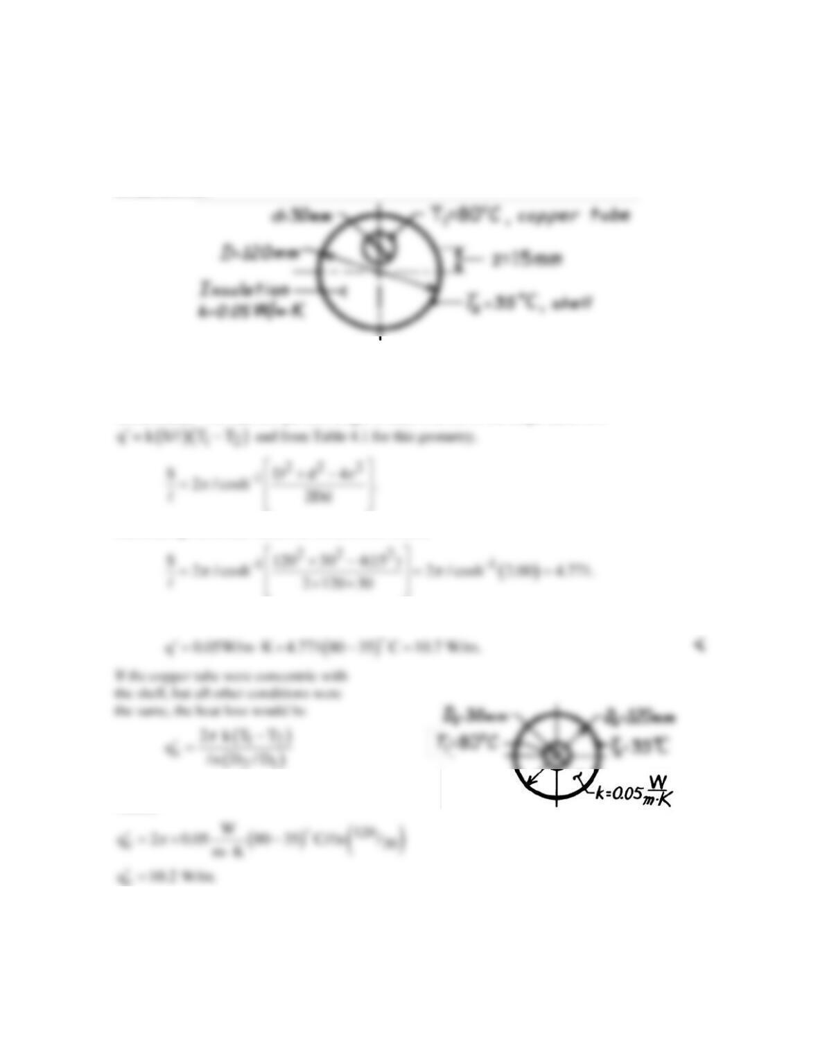
KNOWN: Thin-walled copper tube enclosed by an eccentric cylindrical shell; intervening space
filled with insulation.
FIND: Heat loss per unit length of tube; compare result with that of a concentric tube-shell
arrangement.
SCHEMATIC:
ASSUMPTIONS: (1) Steady-state conditions, (2) Constant properties, (3) Thermal resistances of
copper tube wall and outer shell wall are negligible, (4) Two-dimensional conduction in insulation.
ANALYSIS: The heat loss per unit length written in terms of the shape factor S is
Substituting numerical values, all dimensions in mm,
Hence, the heat loss is
using Eq. 3.32. Substituting numerical
values,
COMMENTS: As expected, the heat loss with the eccentric arrangement is larger than that for the
concentric arrangement. The effect of the eccentricity is to increase the heat loss by (10.7–10.2)/10.2
≈ 5.3%.
PROBLEM 4.18
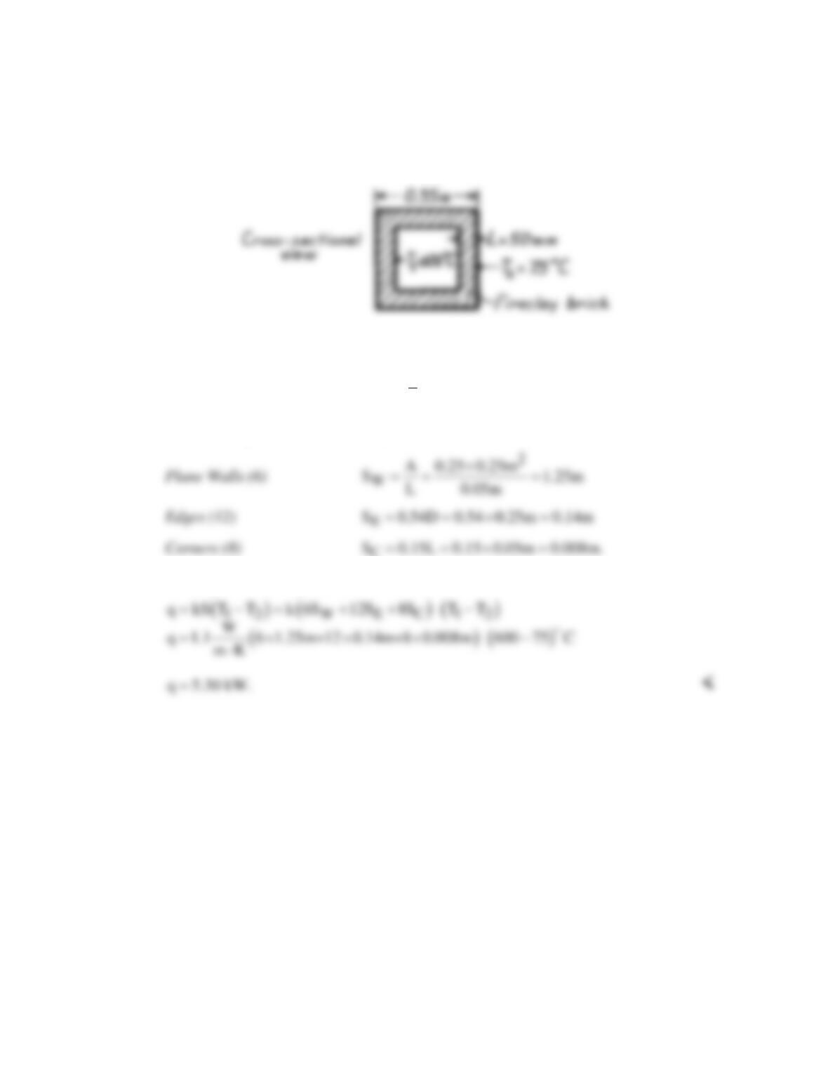
KNOWN: Cubical furnace, 350 mm external dimensions, with 50 mm thick walls.
FIND: The heat loss, q(W).
SCHEMATIC:
ASSUMPTIONS: (1) Steady-state conditions, (2) Two-dimensional conduction, (3)
Constant properties.
PROPERTIES: Table A-3, Fireclay brick
( )
( )
12
T T T / 2 610K : k 1.1 W/m K.=+= ≈ ⋅
ANALYSIS: Using relations for the shape factor from Table 4.1,
C
The heat rate in terms of the shape factors is
COMMENTS: Note that the restrictions for SE and SC have been met.
PROBLEM 4.19
KNOWN: Dimensions of stainless steel pillar and nominal glass temperatures. Contact resistance
between pillar and glass.
FIND: Conduction rate through the pillar.
ASSUMPTIONS: (1) Steady–state conditions, (2) Constant properties, (3) Negligible radiation, (4)
Two–dimensional conduction, (5) Glass behaves as a semi–infinite medium.
PROPERTIES: Table A.1, AISI 302 stainless steel (300 K): kp = 15.1 W/m⋅K. Table A.3, plate glass
(300 K): kg = 1.4 W/m⋅K.
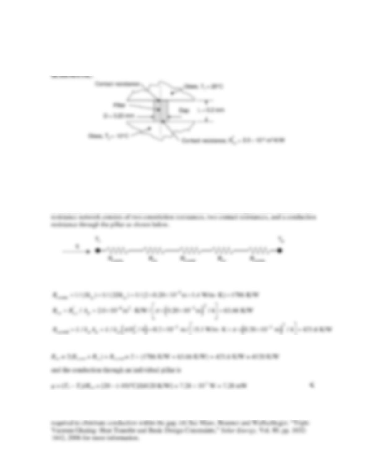
ANALYSIS: Conduction through the pillar results in a depression of the glass temperature adjacent
to the pillar. This is associated with a constriction resistance within each glass sheet. Therefore, the
Using the shape factor for Case 10 of Table 4.1(a) the resistances are:
Therefore, the total resistance is
COMMENTS: (1) Constriction of the heat flow within the glass poses the largest resistance to heat
transfer. (2) Radiation between the two glass sheets exists, and may be important in determining the
overall heat transfer through the window. (3) Extremely high vacuum between the two glass sheets is
PROBLEM 4.20
KNOWN: Temperature, diameter and burial depth of an insulated pipe.
FIND: Heat loss per unit length of pipe.
SCHEMATIC:
ASSUMPTIONS: (1) Steady-state conditions, (2) One-dimensional conduction through
insulation, two-dimensional through soil, (3) Constant properties, (4) Negligible oil
convection and pipe wall conduction resistances.
PROPERTIES: Table A-3, Soil (300K): k = 0.52 W/m⋅K; Table A-3, Cellular glass (365K):
k = 0.069 W/m⋅K.
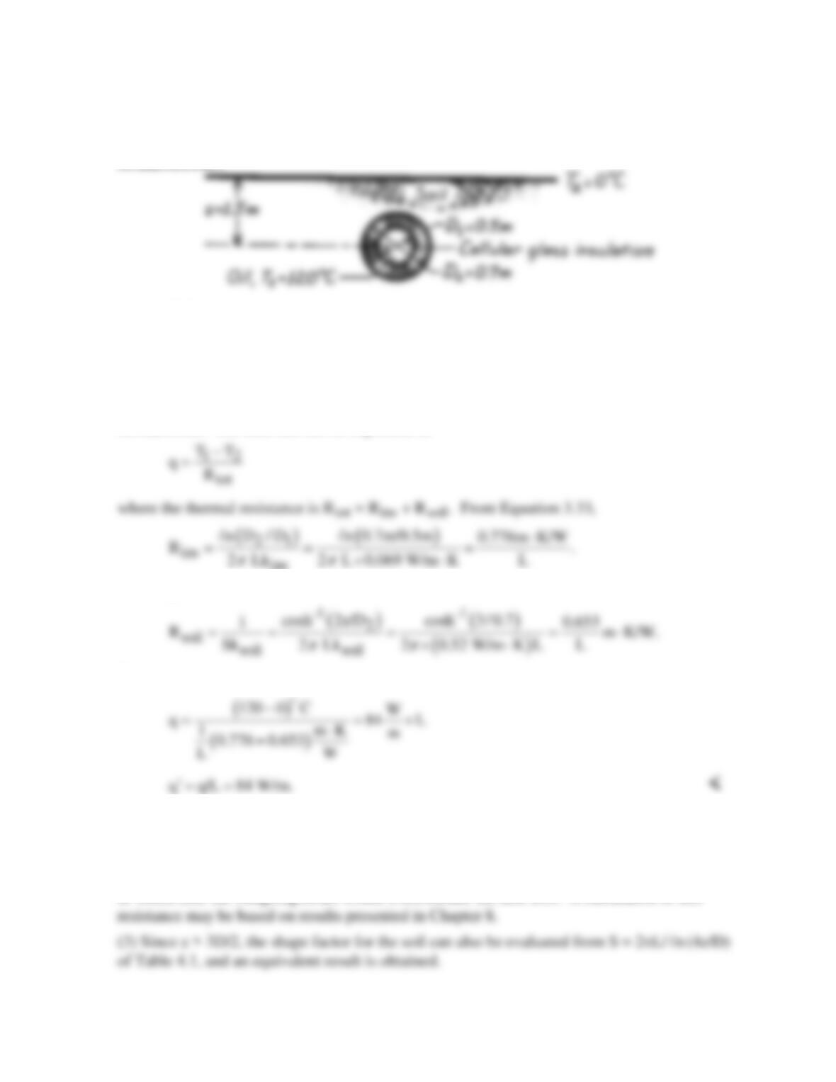
ANALYSIS: The heat rate can be expressed as
From Equation 4.21 and Table 4.1,
Hence,
COMMENTS: (1) Contributions of the soil and insulation to the total resistance are
approximately the same. The heat loss may be reduced by burying the pipe deeper or adding
more insulation.
(2) The convection resistance associated with the oil flow through the pipe may be significant,
in which case the foregoing result would overestimate the heat loss. A calculation of this
PROBLEM 4.21
KNOWN: Operating conditions of a buried superconducting cable.
FIND: Required cooling load.
ASSUMPTIONS: (1) Steady-state conditions, (2) Constant properties, (3) Two-dimensional
conduction in soil, (4) One-dimensional conduction in insulation, (5) Pipe inner surface is at
liquid nitrogen temperature. (6) Negligible contact resistance.
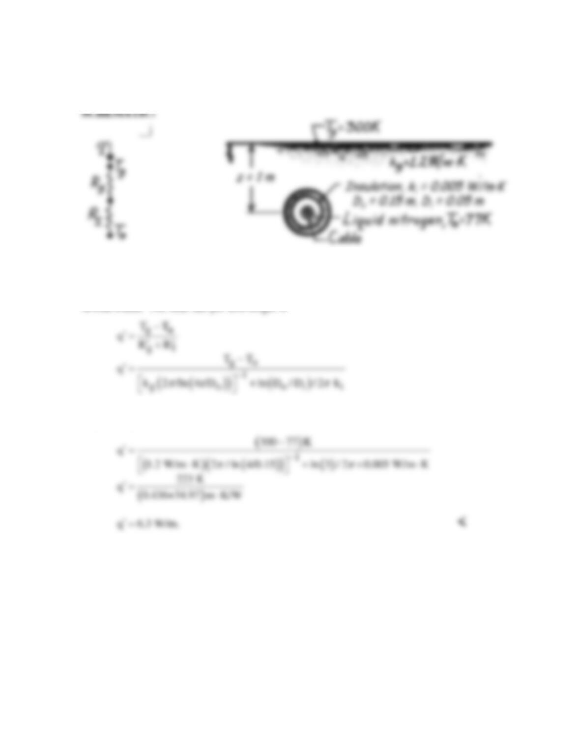
ANALYSIS: The heat rate per unit length is
where Tables 3.3 and 4.1 have been used to evaluate the insulation and ground resistances,
respectively. Hence,
COMMENTS: The heat gain is small and the dominant contribution to the thermal
resistance is made by the insulation. Inclusion of a contact resistance would further reduce the
heat gain.
PROBLEM 4.22
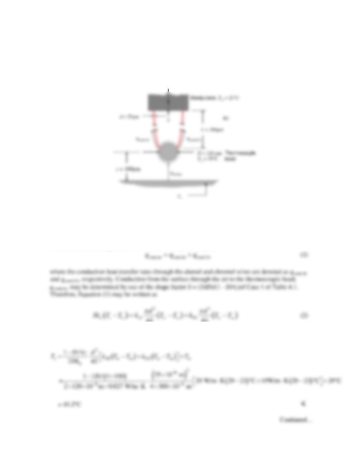
KNOWN: Dimensions and temperature of thermocouple bead and wires. Manipulator temperature,
distance between bead and surface.
FIND: Surface temperature.
SCHEMATIC:
ASSUMPTIONS: (1) Constant properties, (2) Negligible radiation and convection, (3) Isothermal
thermocouple bead, (4) Air behaves as a semi–infinite medium, (5) Steady state conditions.
PROPERTIES: Table A.4, Air (310 K): ka = 0.027 W/m⋅K.
ANALYSIS: An energy balance on the thermocouple bead yields
44
LL
which may be rearranged to yield
PROBLEM 4.22 (Cont.)
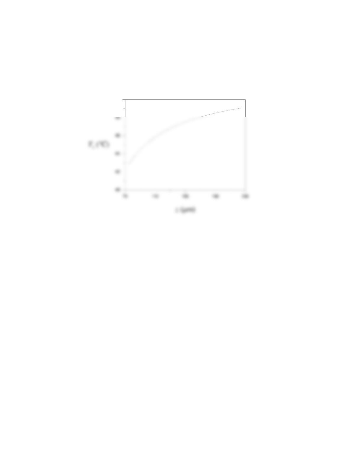
COMMENTS: The required surface temperature to induce the specified thermocouple temperature
and its dependence on the separation distance, z, is shown below. As expected, the required surface
temperature becomes greater as the separation distance increases.
50
PROBLEM 4.23
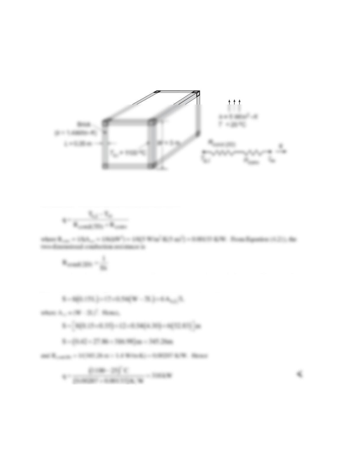
KNOWN: Dimensions, thermal conductivity and inner surface temperature of furnace wall. Ambient
conditions.
FIND: Heat loss.
SCHEMATIC:
ASSUMPTIONS: (1) Steady-state, (2) Uniform convection coefficient over entire outer surface of
container, (3) Negligible radiation losses.
ANALYSIS: From the thermal circuit, the heat loss is
where the shape factor S must include the effects of conduction through the 8 corners, 12 edges and 6
plane walls. Hence, using the relations for Cases 8 and 9 of Table 4.1,
COMMENTS: The heat loss is extremely large and measures should be taken to insulate the furnace.
Radiation losses may be significant, leading to larger heat losses.
PROBLEM 4.24
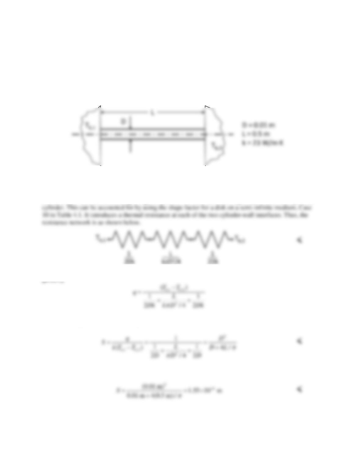
KNOWN: Cylinder extending between two walls. Highly polished surfaces. Walls are at specified
temperatures far from the cylinder.
FIND: (a) Thermal resistance network. (b) Expression for shape factor corresponding to conduction
between Tb,1 and Tb,2. (3) Value of shape factor for specified cylinder diameter, length, and thermal
conductivity.
SCHEMATIC:
ASSUMPTIONS: (1) Steady–state conditions. (2) Constant properties. (3) Walls are semi–infinite. (4)
Walls and cylinder have same thermal conductivity.
ANALYSIS: (a) Heat conducting along the cylinder will alter the wall temperature in the vicinity of the
(b) According to the resistance network, when kw = kc = k, the heat transfer rate between the two walls is
given by
Then from Equation 4.20, the shape factor is
(c) The value of the shape factor is
COMMENTS: (1) As long as the materials all have the same thermal conductivity, the value of the shape
factor is independent of the thermal conductivity. (2) The effect of the cylinder on the wall temperature
becomes negligible as the thermal resistance of the cylinder increases, for example by increasing L.
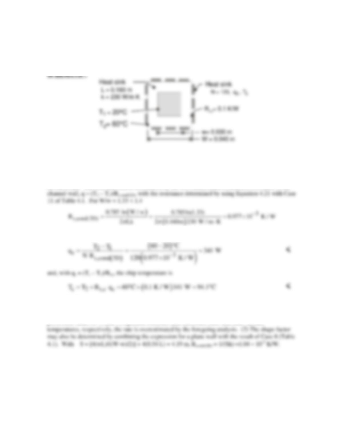
PROBLEM 4.25
KNOWN: Dimensions and surface temperatures of a square channel. Number of chips mounted on
outer surface and chip thermal contact resistance.
FIND: Heat dissipation per chip and chip temperature.
ASSUMPTIONS: (1) Steady state, (2) Approximately uniform channel inner and outer surface
temperatures, (3) Two–dimensional conduction through channel wall (negligible end-wall effects), (4)
Constant thermal conductivity.
ANALYSIS: The total heat rate is determined by the two-dimensional conduction resistance of the
The heat rate per chip is then
COMMENTS: (1) By acting to spread heat flow lines away from a chip, the channel wall provides
an excellent heat sink for dissipating heat generated by the chip. However, recognize that, in practice,
there will be temperature variations on the inner and outer surfaces of the channel, and if the
prescribed values of T1 and T2 represent minimum and maximum inner and outer surface
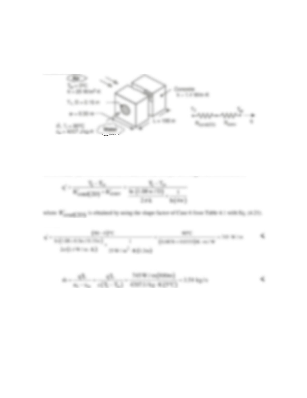
PROBLEM 4.26
KNOWN: Dimensions and thermal conductivity of concrete duct. Convection conditions of ambient
air. Inlet temperature of water flow through the duct.
FIND: (a) Heat loss per duct length near inlet, (b) Minimum allowable flow rate corresponding to
maximum allowable temperature rise of water.
SCHEMATIC:
ASSUMPTIONS: (1) Steady state, (2) Negligible water–side convection resistance, pipe wall
conduction resistance, and pipe/concrete contact resistance (temperature at inner surface of concrete
corresponds to that of water), (3) Constant properties, (4) Negligible flow work and kinetic and
potential energy changes.
ANALYSIS: (a) From the thermal circuit, the heat loss per unit length near the entrance is
Hence,
(b) From Eq. (1.12d), with
q qL
′
=
and
( )
io
T T 5 C,−=°
io io
COMMENTS: The small reduction in the temperature of the water as it flows from inlet to outlet
induces a slight departure from two-dimensional conditions and a small reduction in the heat rate per
unit length. A slightly conservative value (upper estimate) of
m
is therefore obtained in part (b).
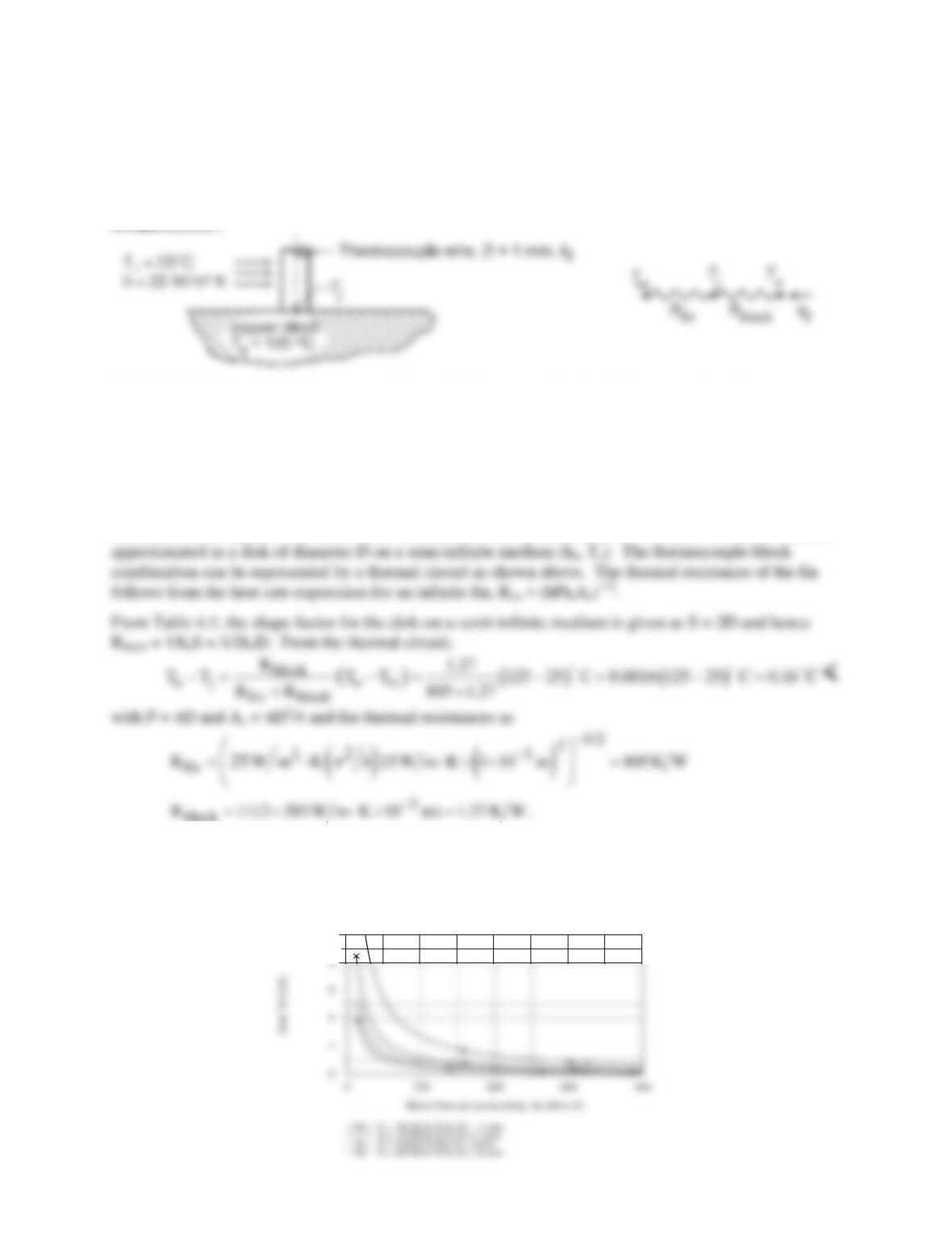
PROBLEM 4.27
KNOWN: Long constantan wire butt-welded to a large copper block forming a thermocouple junction
on the surface of the block.
FIND: (a) The measurement error (Tj – To) for the thermocouple for prescribed conditions, and (b)
Compute and plot (Tj – To) for h = 5, 10 and 25 W/m2⋅K for block thermal conductivity 15 ≤ k ≤ 400
W/m⋅K. When is it advantageous to use smaller diameter wire?
SCHEMATIC:
ASSUMPTIONS: (1) Steady-state conditions, (2) Thermocouple wire behaves as a fin with constant
heat transfer coefficient, (3) Copper block has uniform temperature, except in the vicinity of the junction.
PROPERTIES: Table A-1, Copper (pure, 400 K), kb = 393 W/m⋅K; Constantan (350 K), kt ≈ 25
W/m⋅K.
ANALYSIS: The thermocouple wire behaves as a long fin permitting heat to flow from the surface
thereby depressing the sensing junction temperature below that of the block To. In the block, heat flows
into the circular region of the wire-block interface; the thermal resistance to heat flow within the block is
block
(b) We keyed the above equations into the IHT workspace, performed a sweep on kb for selected values
of h and created the plot shown. When the block thermal conductivity is low, the error (To – Tj) is larger,
increasing with increasing convection coefficient. A smaller diameter wire will be advantageous for low
values of kb and higher values of h.
5
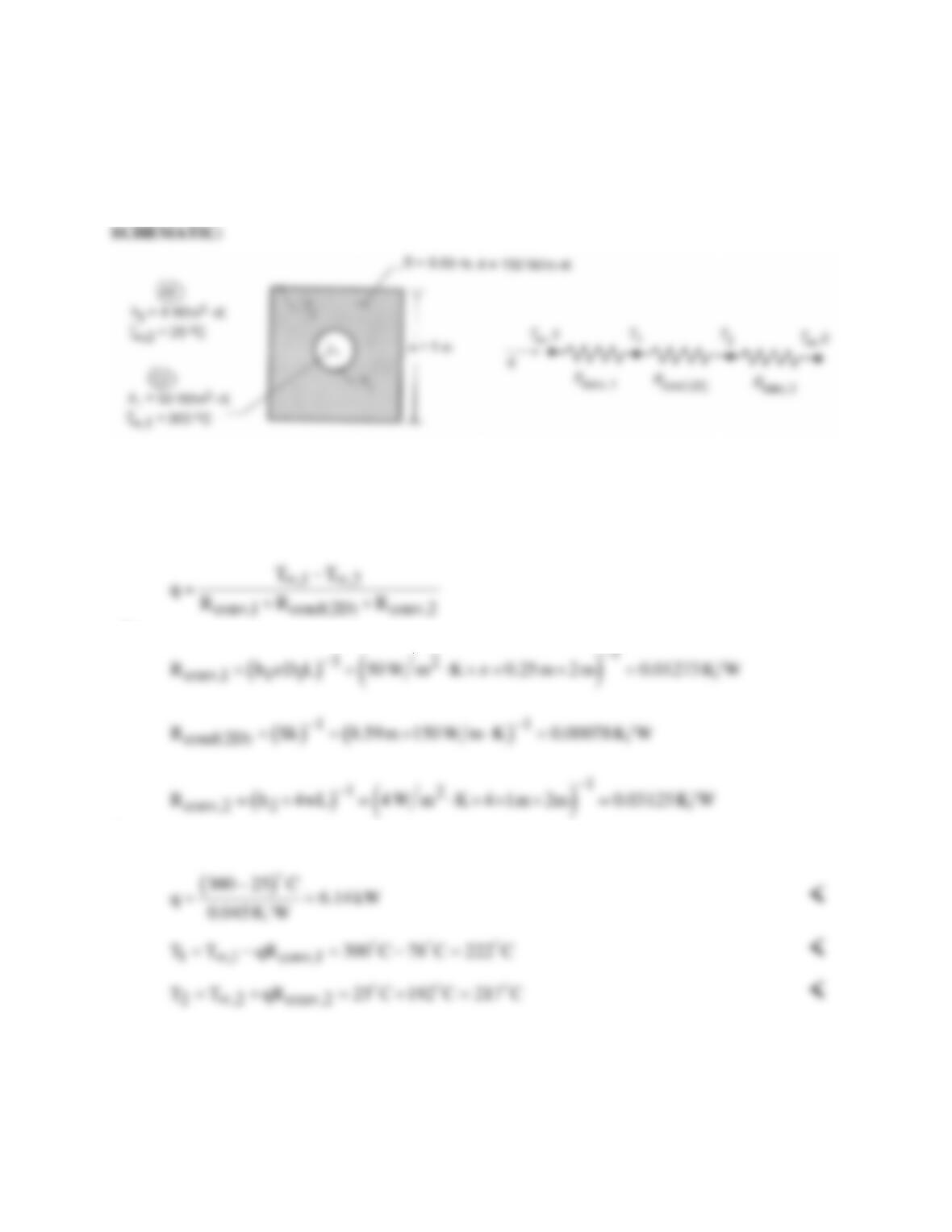
PROBLEM 4.28
KNOWN: Dimensions, shape factor, and thermal conductivity of square rod with drilled interior hole.
Interior and exterior convection conditions.
FIND: Heat rate and surface temperatures.
ASSUMPTIONS: (1) Steady-state, two-dimensional conduction, (2) Constant properties, (3) Uniform
convection coefficients at inner and outer surfaces.
ANALYSIS: The heat loss can be expressed as
where
Hence,
COMMENTS: The largest resistance is associated with convection at the outer surface, and the
conduction resistance is much smaller than both convection resistances. Hence, (T2 – T∞,2) > (T∞,1 – T1)
>> (T1 – T2).
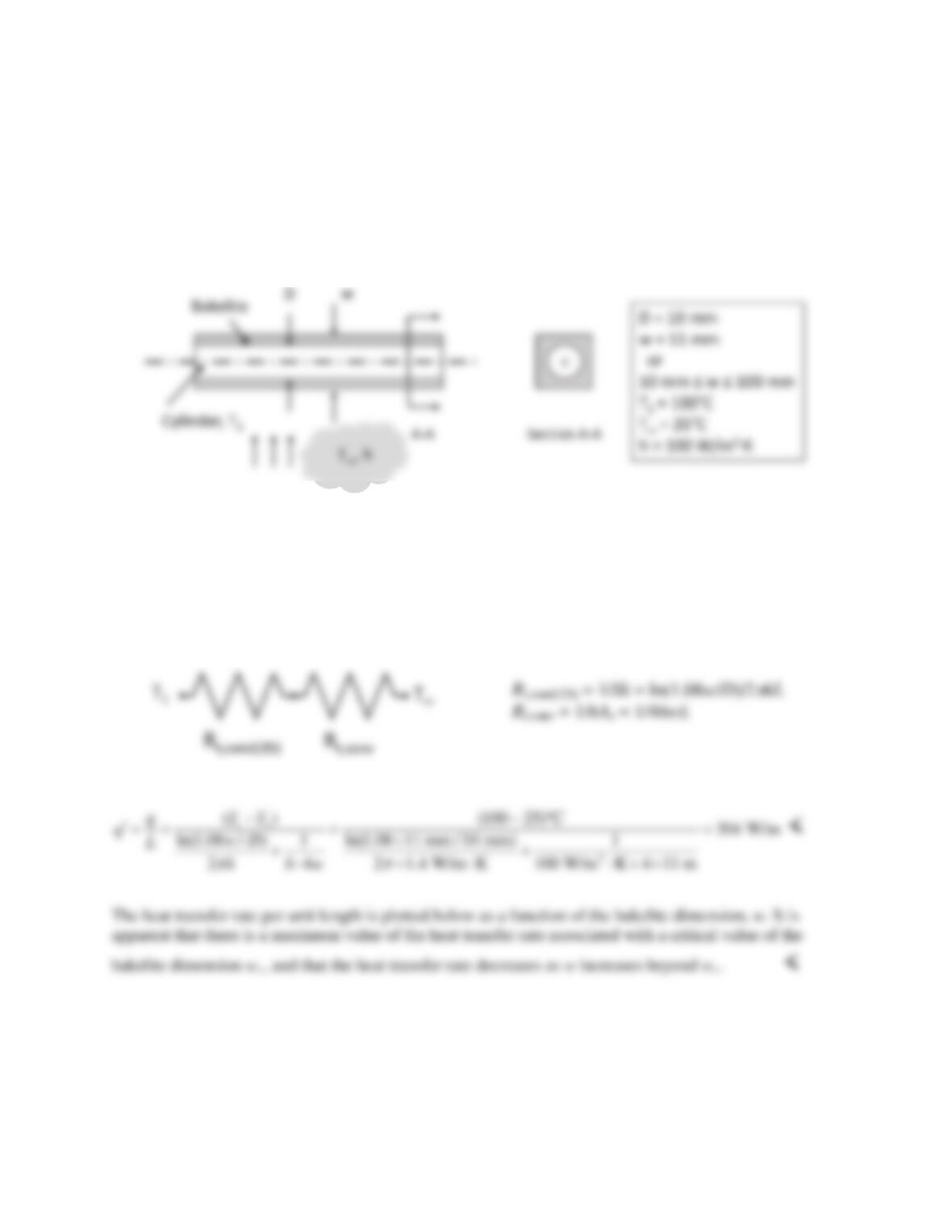
PROBLEM 4.29
KNOWN: Cylinder of specified diameter within square bakelite coating of dimension w on a side.
Cylinder temperature, environment temperature, and heat transfer coefficient.
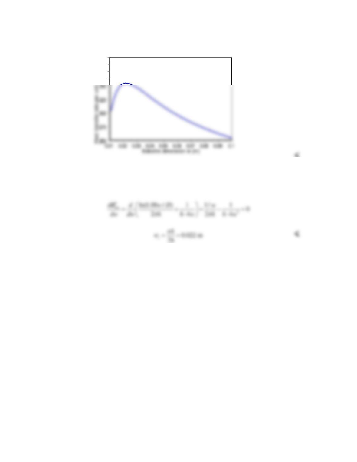
FIND: Heat transfer rate per unit length of cylinder. Plot heat transfer rate for 10 mm < w < 100 mm.
Explain dependence of heat transfer rate on bakelite thickness. Find critical value of w that maximizes
heat transfer from cylinder.
SCHEMATIC:
ASSUMPTIONS: (1) Steady–state conditions, (2) Uniform properties.
PROPERTIES: Table A–3, Bakelite, (T = 300 K): k = 1.4 W/m⋅K.
ANALYSIS: The resistance network between the cylinder and the environment is shown below, where
Rt,cond(2D) = 1/Sk (Equation 4.21), and the shape factor S for heat transfer through the bakelite is given in
Table 4.1, Case 6.
Thus the heat transfer rate per unit cylinder length is
The existence of a maximum heat transfer rate is because of the competing effects that as w
increases, the thermal resistance of the bakelite increases, but the thermal resistance for
convection decreases because of the increasing surface area.
Continued…
PROBLEM 4.29 (Cont.)
Heat Transfer Rate per Unit Length
400
375
<
Heat transfer is maximized when thermal resistance is minimized. Therefore the critical bakelite
dimension can be determined by differentiating the thermal resistance with respect to w and
setting the result to zero:
COMMENTS: The critical bakelite thickness is very similar to the concept of a critical thickness of
insulation on a cylinder.
PROBLEM 4.30
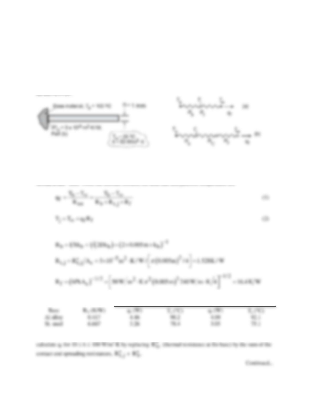
KNOWN: Long fin of aluminum alloy with prescribed convection coefficient attached to different base
materials (aluminum alloy or stainless steel) with and without thermal contact resistance
t,j
R′′
at the
junction.
FIND: (a) Heat rate qf and junction temperature Tj for base materials of aluminum and stainless steel,
(b) Repeat calculations considering thermal contact resistance,
t,j
R′′
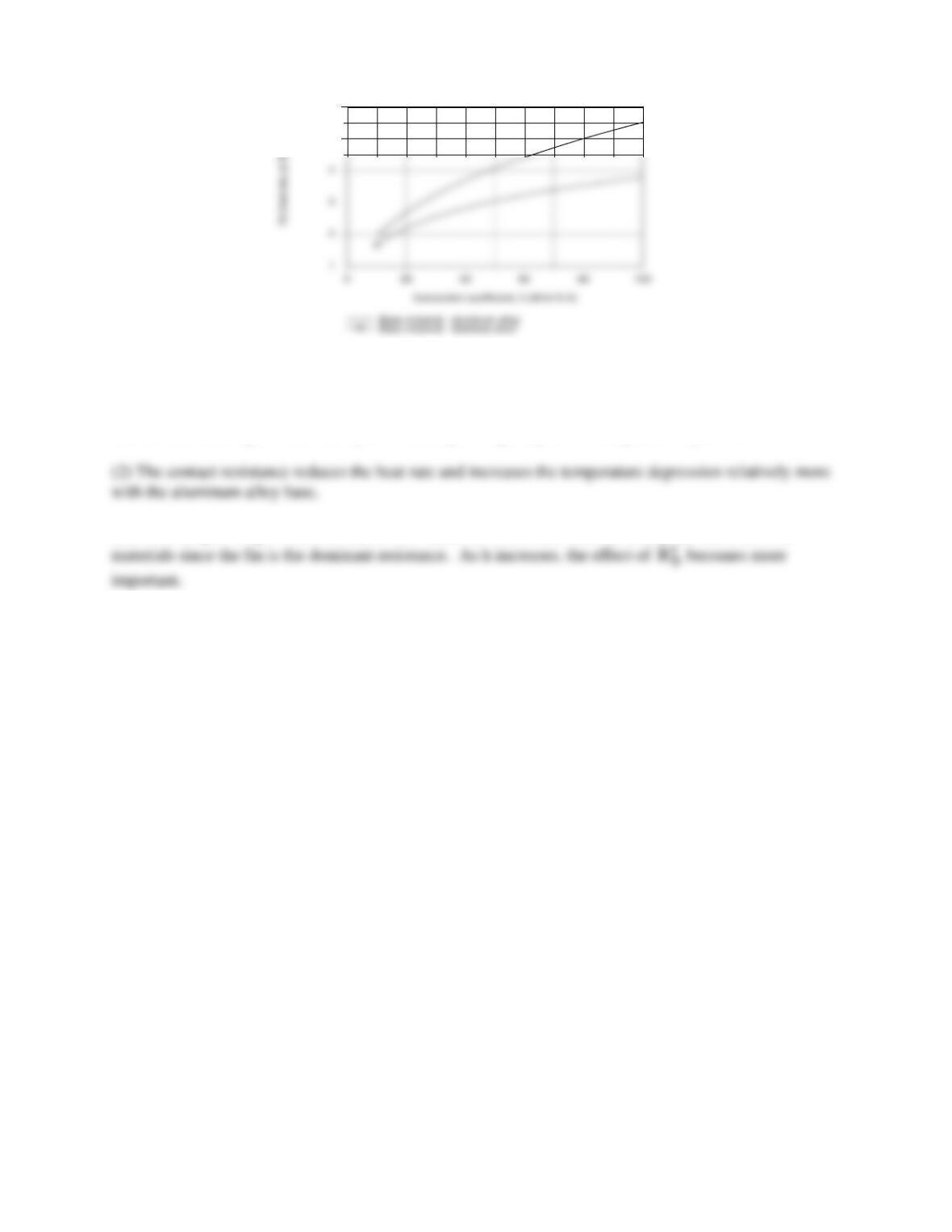
, and (c) Plot as a function of h for
the range 10 ≤ h ≤ 1000 W/m2⋅K for each base material.
SCHEMATIC:
ASSUMPTIONS: (1) Steady-state conditions, (2) Constant properties, (3) Infinite fin.
PROPERTIES: (Given) Aluminum alloy, k = 240 W/m⋅K, Stainless steel, k = 15 W/m⋅K.
ANALYSIS: (a,b) From the thermal circuits, the heat rate and junction temperature are
and, with P = πD and Ac = πD2/4, from Tables 4.1 and 3.4 find
Without
t,j
R′′
With
t,j
R′′
(c) We used the IHT Model for Extended Surfaces, Performance Calculations, Rectangular Pin Fin to
PROBLEM 4.30 (Cont.)
5
6
COMMENTS: (1) From part (a), the aluminum alloy base material has negligible effect on the fin heat
rate and depresses the base temperature by only 2°C. The effect of the stainless steel base material is
substantial, reducing the heat rate by 27% and depressing the junction temperature by 25°C.
(3) From the plot of qf vs. h, note that at low values of h, the heat rates are nearly the same for both