PROBLEM 4.148
Determine the reactions at A and B when a 150 mm.
SOLUTION
Free-Body Diagram:
PROBLEM 4.149
For the frame and loading shown, determine the reactions at A and C.
SOLUTION
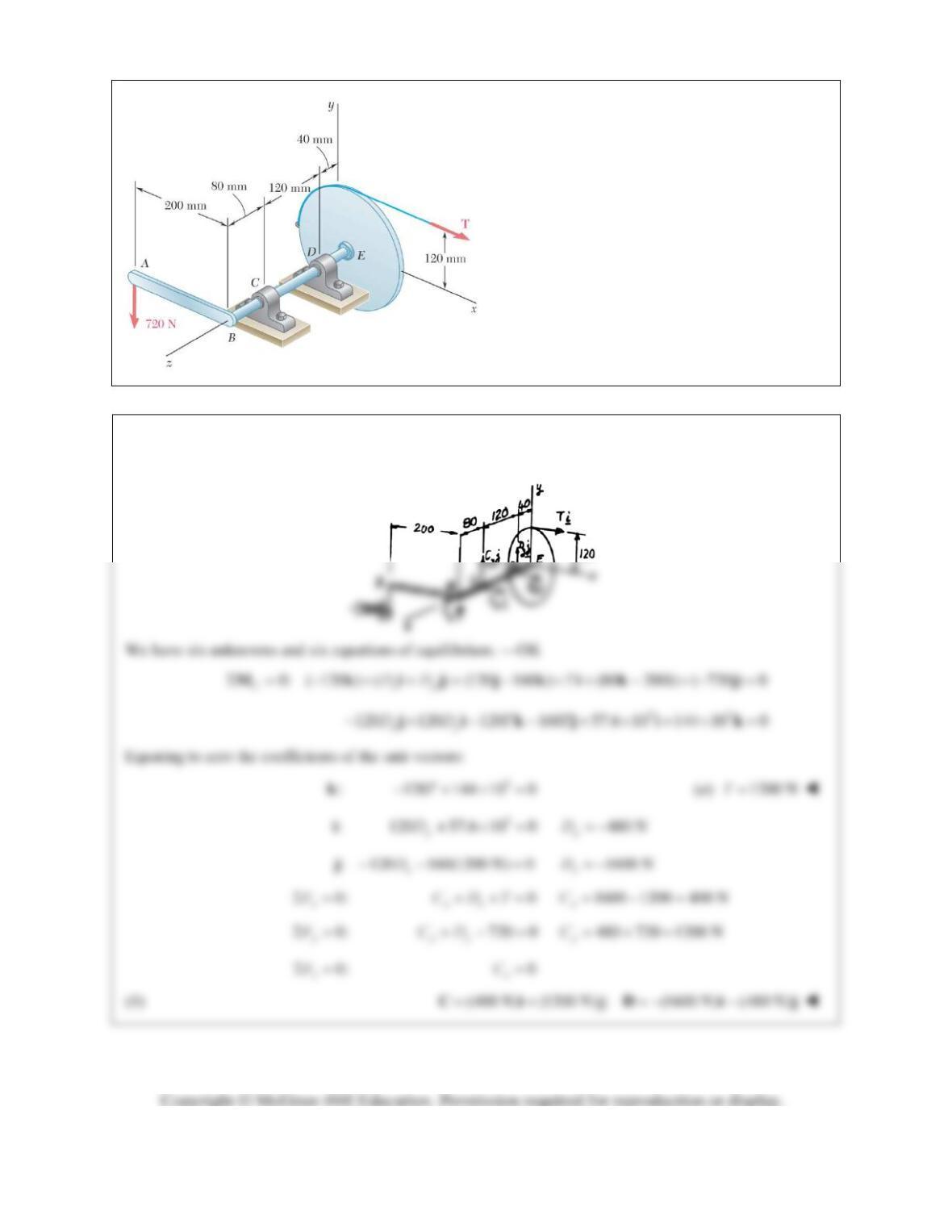
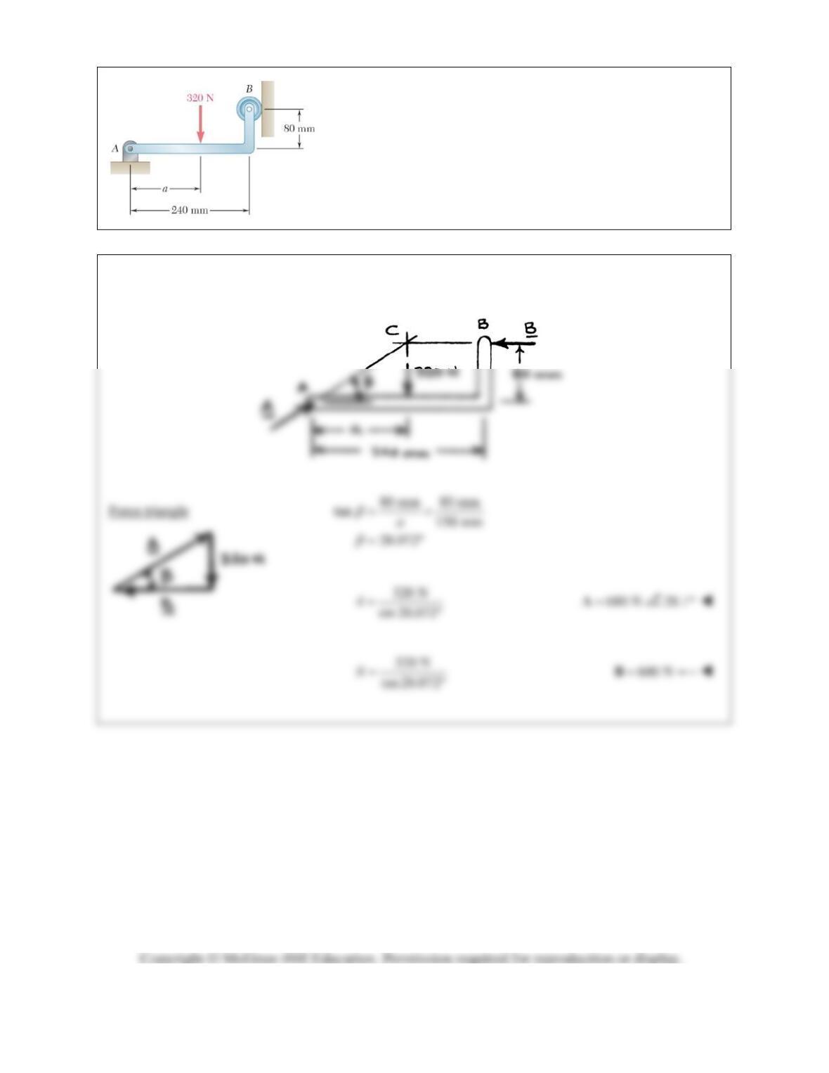
PROBLEM 4.150
A 200-mm lever and a 240-mm-diameter pulley
are welded to the axle BE that is supported by
bearings at C and D. If a 720-N vertical load is
applied at A when the lever is horizontal,
determine (a) the tension in the cord, (b) the
reactions at C and D. Assume that the bearing at
D does not exert any axial thrust.
SOLUTION
Dimensions in mm
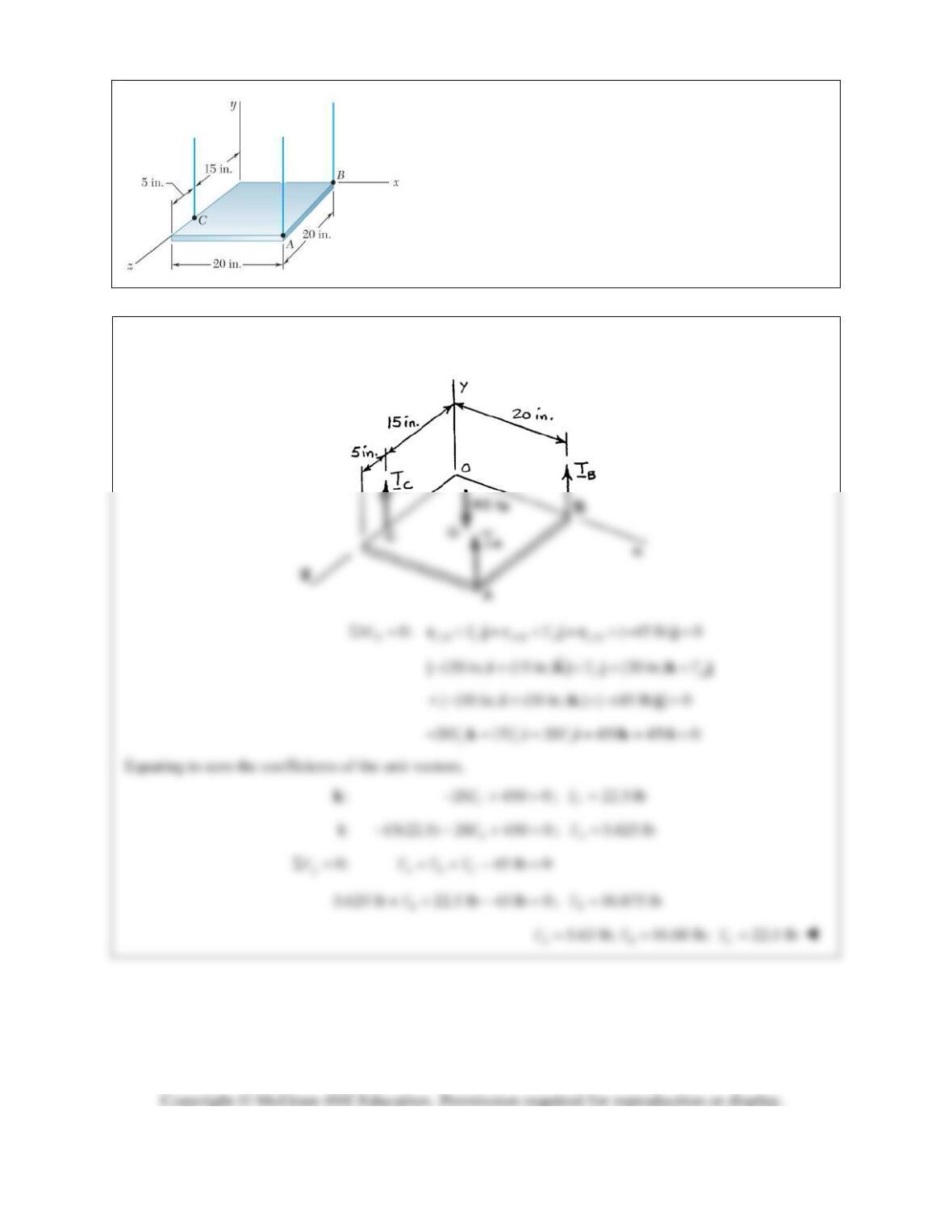
PROBLEM 4.151
The 45-lb square plate shown is supported by three vertical
wires. Determine the tension in each wire.
SOLUTION
Free-Body Diagram:
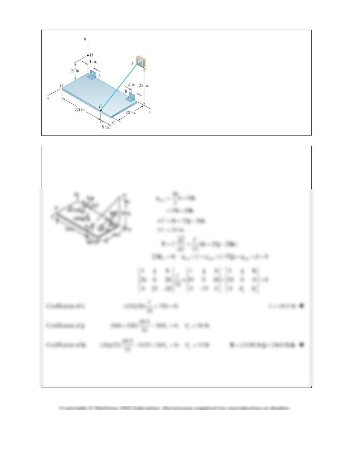
PROBLEM 4.152
The rectangular plate shown weighs 75 lb and is held in the
position shown by hinges at A and B and by cable EF.
Assuming that the hinge at B does not exert any axial
thrust, determine (a) the tension in the cable, (b) the
reactions at A and B.
SOLUTION
/
/
(38 8) 30
(30 4) 20
26 20
BA
EA
rii
rik
ik
PROBLEM 4.152 (Continued)
0: (75 lb) 0 FABT j
Coefficient of i: 8(49.5) 0 12.00 lb
33
xx
AA
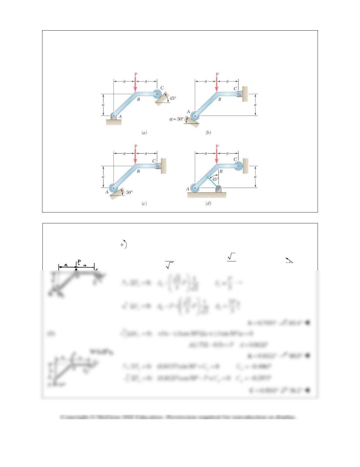
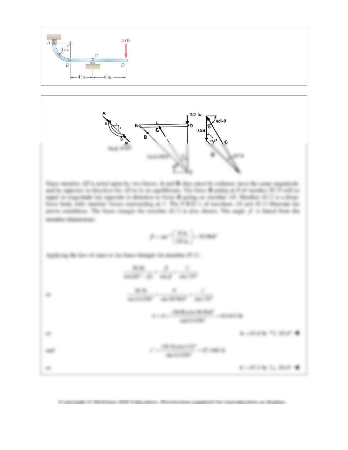
PROBLEM 4.153
A force P is applied to a bent rod ABC, which may be supported in four different ways as shown. In each
case, if possible, determine the reactions at the supports.
SOLUTION
(a)
0: ( sin 45 )2 (cos 45 ) 0
Aa
MPCa a
32
CP 2
3
CP
0.471PC
45°
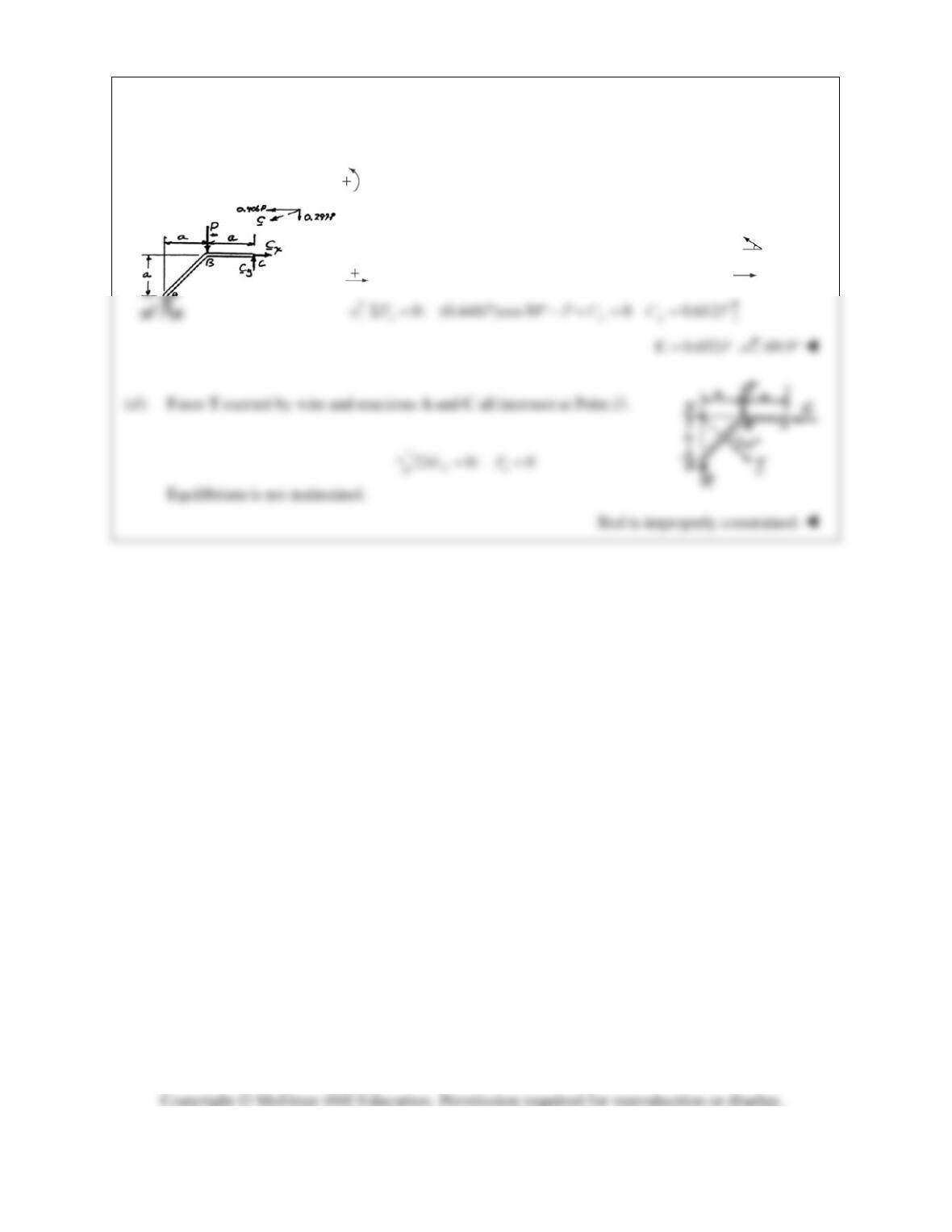
PROBLEM 4.153 (Continued)
(c)
0: ( cos30 )2 ( sin 30 ) 0
C
MPaAaAa
(1.732 0.5) 0.448APAP
0.448PA
60.0°
0: (0.448 )sin 30 0 0.224
xxx
FPCCP
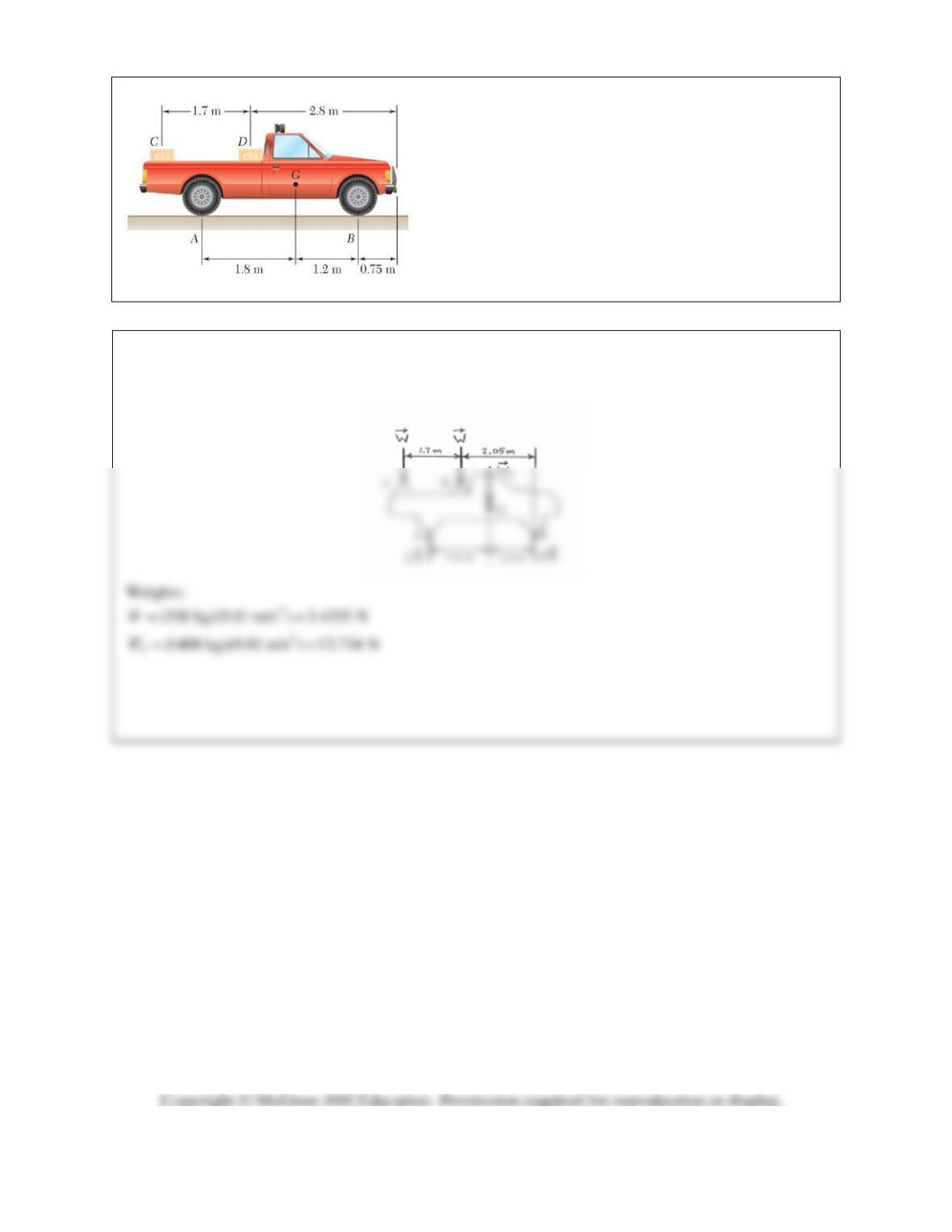
PROBLEM 4.F1
Two crates, each of mass 350 kg, are placed as shown in
the bed of a 1400-kg pick-up truck. Draw the free-body
diagram needed to determine the reactions at each of the
two rear wheels A and front wheels B.
SOLUTION
Free-Body Diagram of Truck:
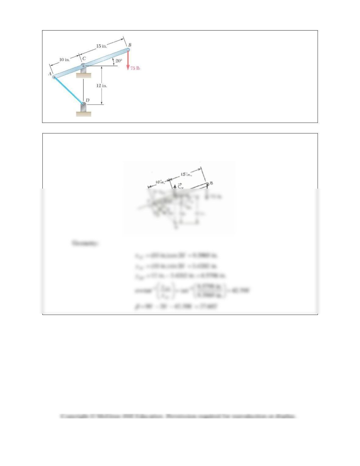
PROBLEM 4.F2
A lever AB is hinged at C and attached to a control cable at A.
If the lever is subjected to a 75-lb vertical force at B, draw the
free-body diagram needed to determine the tension in the cable
and the reaction at C.
SOLUTION
Free-Body Diagram of Lever
AB
:
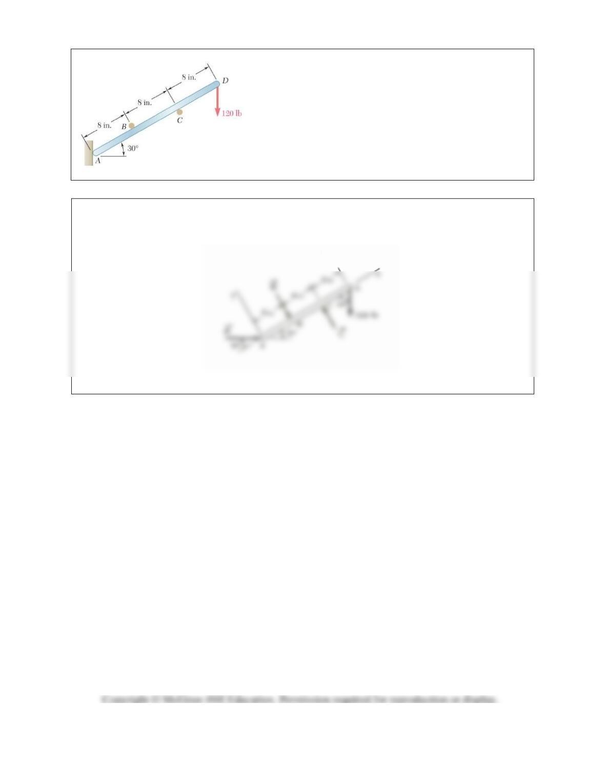
PROBLEM 4.F3
A light rod AD is supported by frictionless pegs at B and C and
rests against a frictionless wall at A. A vertical 120-lb force is
applied at D. Draw the free-body diagram needed to determine
the reactions at A, B, and C.
SOLUTION
Free-Body Diagram of Rod
AD
:
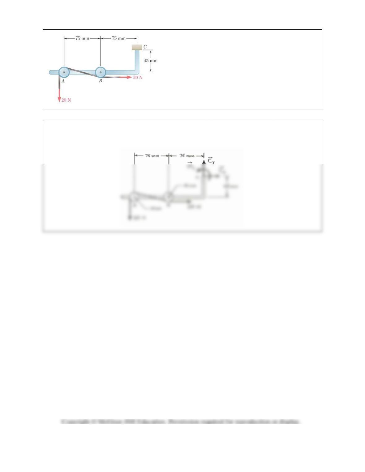
PROBLEM 4.F4
A tension of 20 N is maintained in a tape as it passes
through the support system shown. Knowing that the
radius of each pulley is 10 mm, draw the free-body
diagram needed to determine the reaction at C.
SOLUTION
Free-Body Diagram of Support System:
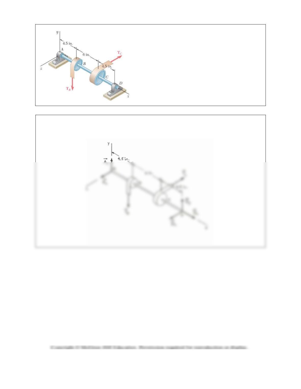
PROBLEM 4.F5
Two tape spools are attached to an axle supported by
bearings at A and D. The radius of spool B is 1.5 in. and
the radius of spool C is 2 in. Knowing that T
B
= 20 lb and
that the system rotates at a constant rate, draw the free-
body diagram needed to determine the reactions at A and
D. Assume that the bearing at A does not exert any axial
thrust and neglect the weights of the spools and axle.
SOLUTION
Free-Body Diagram of Axle-Spool System:
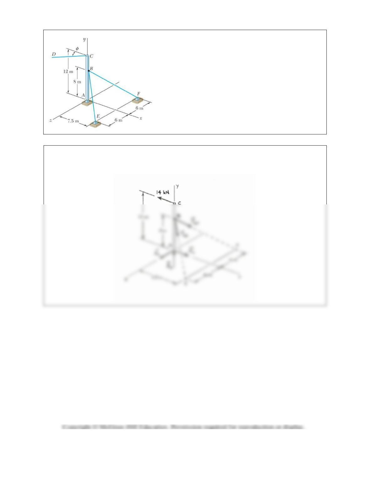
PROBLEM 4.F6
A 12-m pole supports a horizontal cable CD and is held by a
ball and socket at A and two cables BE and BF. Knowing that
the tension in cable CD is 14 kN and assuming that CD is
parallel to the x axis (
= 0), draw the free-body diagram
needed to determine the tension in cables BE and BF and the
reaction at A.
SOLUTION
Free-Body Diagram of Pole:
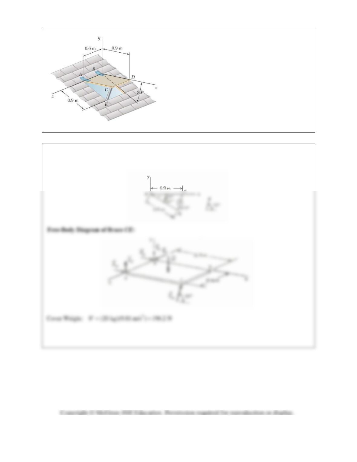
PROBLEM 4.F7
A 20-kg cover for a roof opening is hinged at corners A
and B. The roof forms an angle of 30 with the
horizontal, and the cover is maintained in a horizontal
position by the brace CE. Draw the free-body diagram
needed to determine the magnitude of the force exerted
by the brace and the reactions at the hinges. Assume that
the hinge at A does not exert any axial thrust.
SOLUTION
Geometry of Brace
CE
: