1
CHAPTER 4
Problem 4.1
Show that the maximum deformation u0 of an SDF
system due to a unit impulse force, p(t) = δ(t), is
n
Plot this result as a function of ζ. Comment on the influ-
ence of damping on the maximum response.
Solution:
Equation (4.1.7) with
0 gives the response to
pt t() ()
:
The condition for ut()
attaining a maximum is du d
t
0:
or
or
The maximum displacement is given by Eq. (a) evaluated
at t given by Eq. (b). For this t,
Substituting Eqs. (b) and (c) in Eq. (a) gives
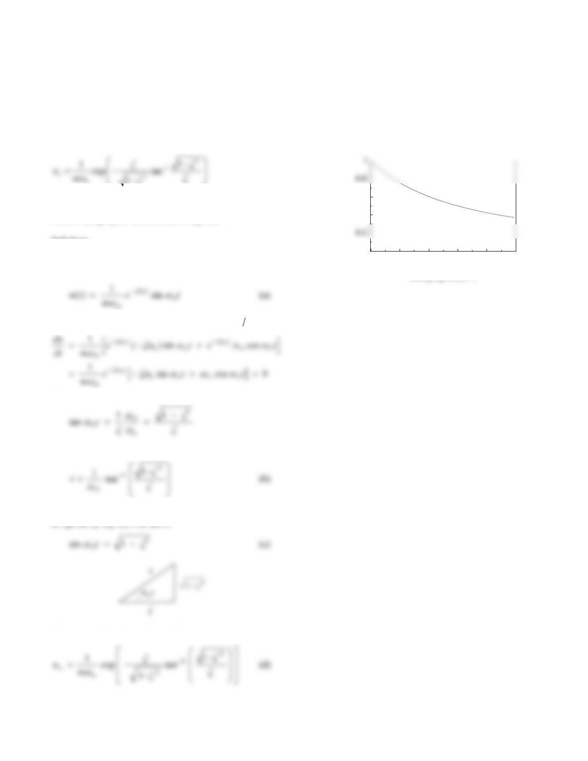
From Eq. (d) mu
no
is plotted against
.
The effect of damping is small; e.g., 10% damping
reduces the response by about 15%.
0 0.2 0.4 0.6 0.8 1
0
0.4
0.6
muo
n
Damping Ratio,
2
Problem 4.2
Consider the deformation response g(t) of an SDF system
to a unit step function p(t) = 1, t ≥ 0, and h(t) due to a unit
impulse p(t) = δ(t). Show that h(t) = ġ(t).
Solution:
Response to a step function is given by Eq. (4.3.5);
for po1 it becomes
The response to a unit impulse force is given by Eq.
(4.1.7) with
0:
From Eq. (a),
Canceling the cos
D
t terms gives
t
k
etg
DDn
t
n
sin
1
1
)(
2
2
3
Problem 4.3
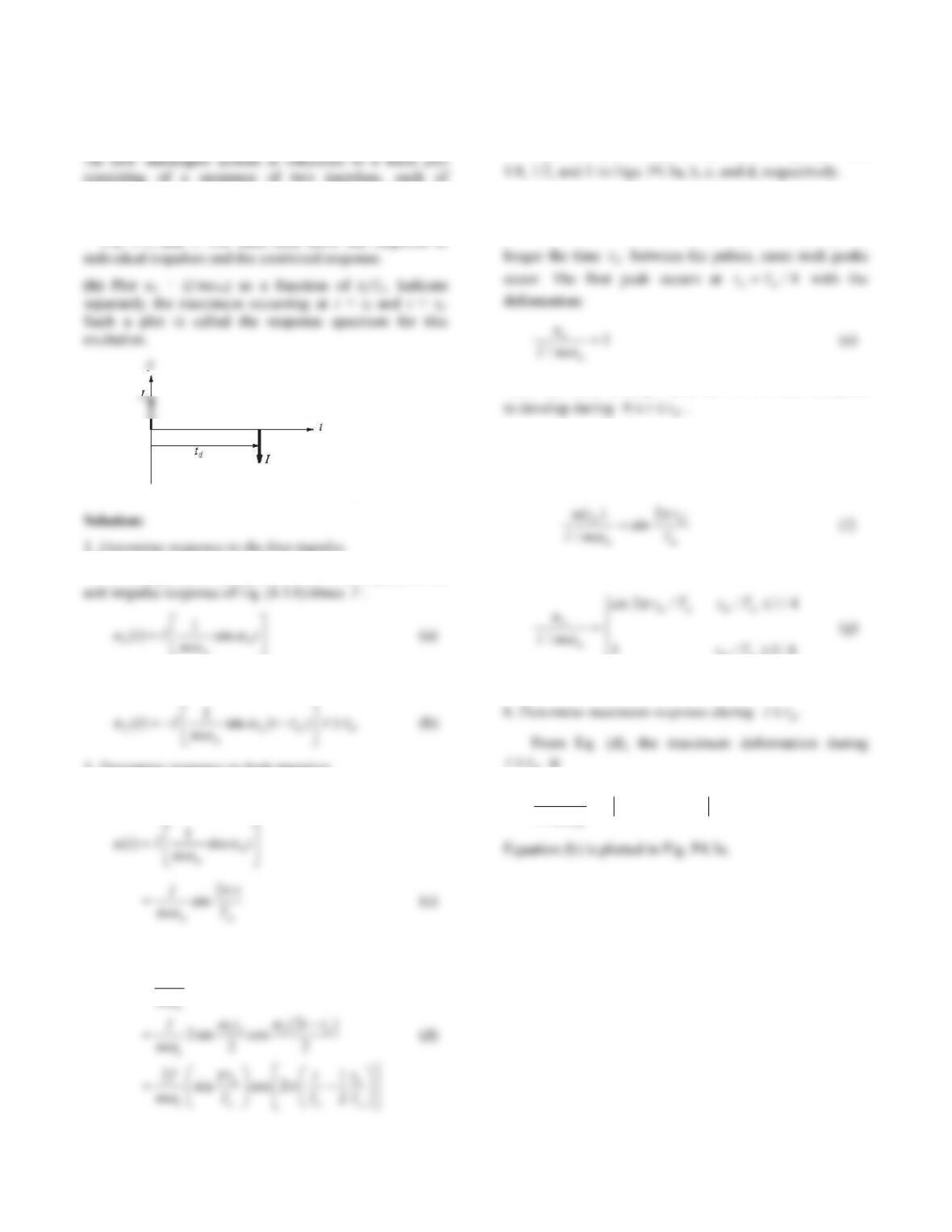
consisting of a sequence of two impulses, each of
magnitude I, as shown in Fig. P4.3.
(a) Plot the displacement response of the system for td /Tn
= 1/8, 1/4, and 1. For each case show the response to
Figure P4.3
1. Determine response to the first impulse.
The response of the system to the first impulse is the
n
2. Determine response to the second impulse.
3. Determine response to both impulses.
For 0tt
d :
For tt
d
:
( ) [sin sin ( )]
nnd
I
ut t t t
m
4. Plot displacement response.
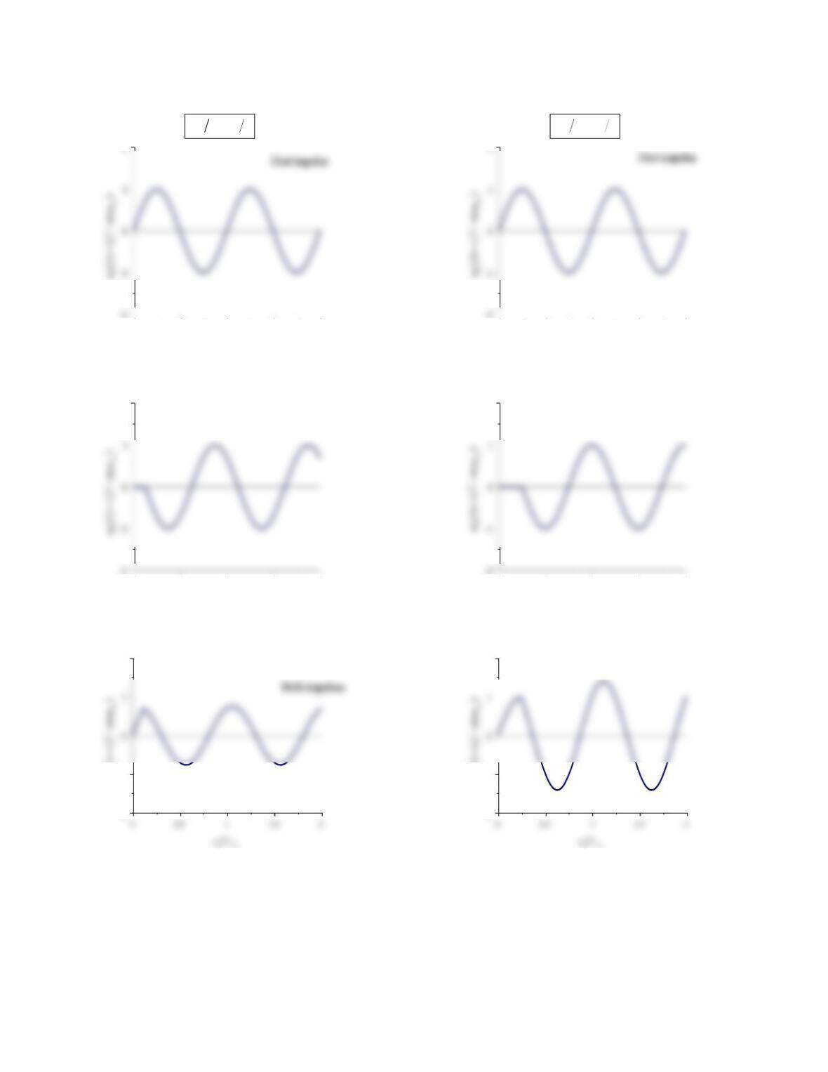
Equations (c) and (d) are plotted for tT
dn
/1/8,
5. Determine maximum response during 0tt
d.
The number of peaks in u(t) depend on tT
dn
/; the
Thus td must be longer than Tn/4for at least one peak
If td is shorter than Tn/4no peak will develop
during 0tt
d and the response simply builds up from
zero to u(td) , where
The maximum deformation during 0tt
d is
nd
Equation (g) is plotted in Fig. P4.3e.
d
)/(sin2
/nd
oTt
mI
u
(h)
4
00.511.52
tT
dn
18
00.511.52
2
Second impulse
-2
-1
2
utIm
() ( / )
Figure P4.3a
00.511.52
tT
dn
14
00.511.52
2Second impulse
-2
-1
2
utIm
() ( / )
Both impulses
Figure P4.3b
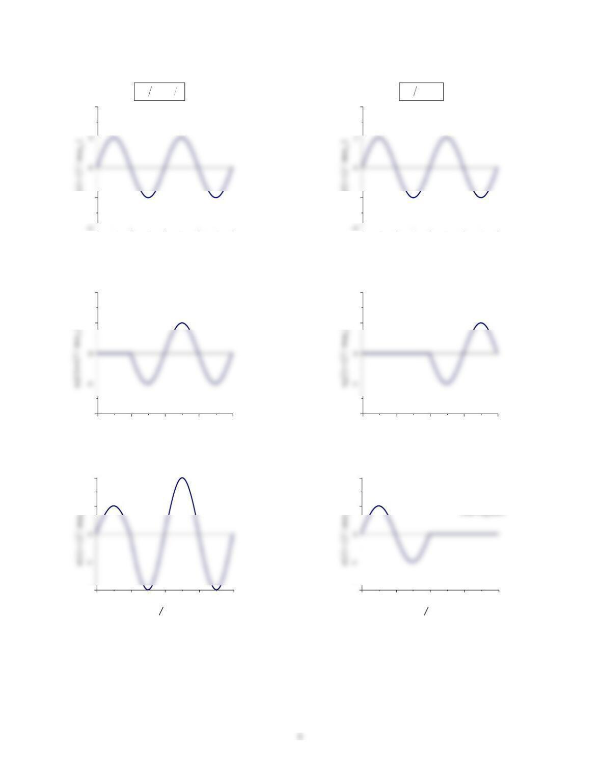
00.511.52
-1
2
ut I mn1() ( / )
tT
dn12
First impulse
00.511.52
-2
1
2Second impulse
00.511.52
-2
1
2
n
tT
n
Both impulses
Figure P4.3c
00.511.52
-1
2
ut I mn1() ( / )
tT
dn1
First impulse
00.511.52
-2
1
2Second impulse
0 0.5 1 1.5 2
-2
1
2
n
tT
n
Both impulses
Figure P4.3d
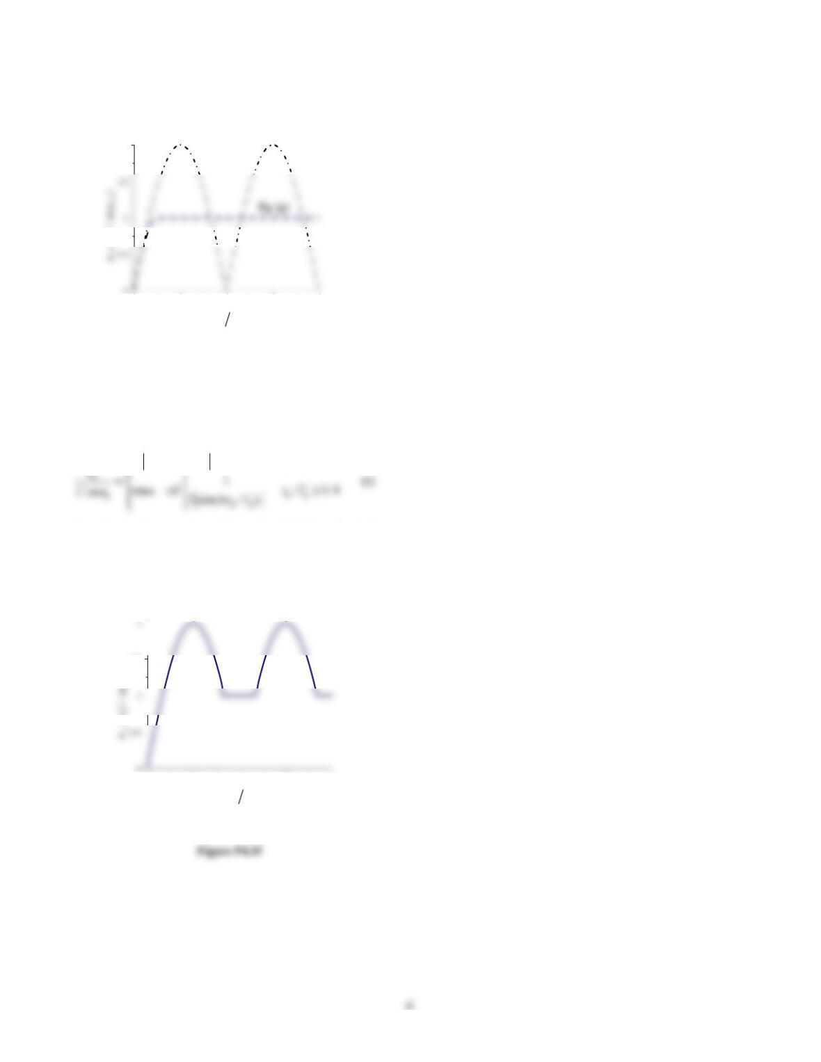
00.511.52
2
(/ )
tT
dn
Eq. (h)
Figure P4.3e
7. Determine the overall maximum response.
From Eqs. (g) and (h), the overall maximum response
is given by
4/1/)/(sin2
ndnd
TtTt
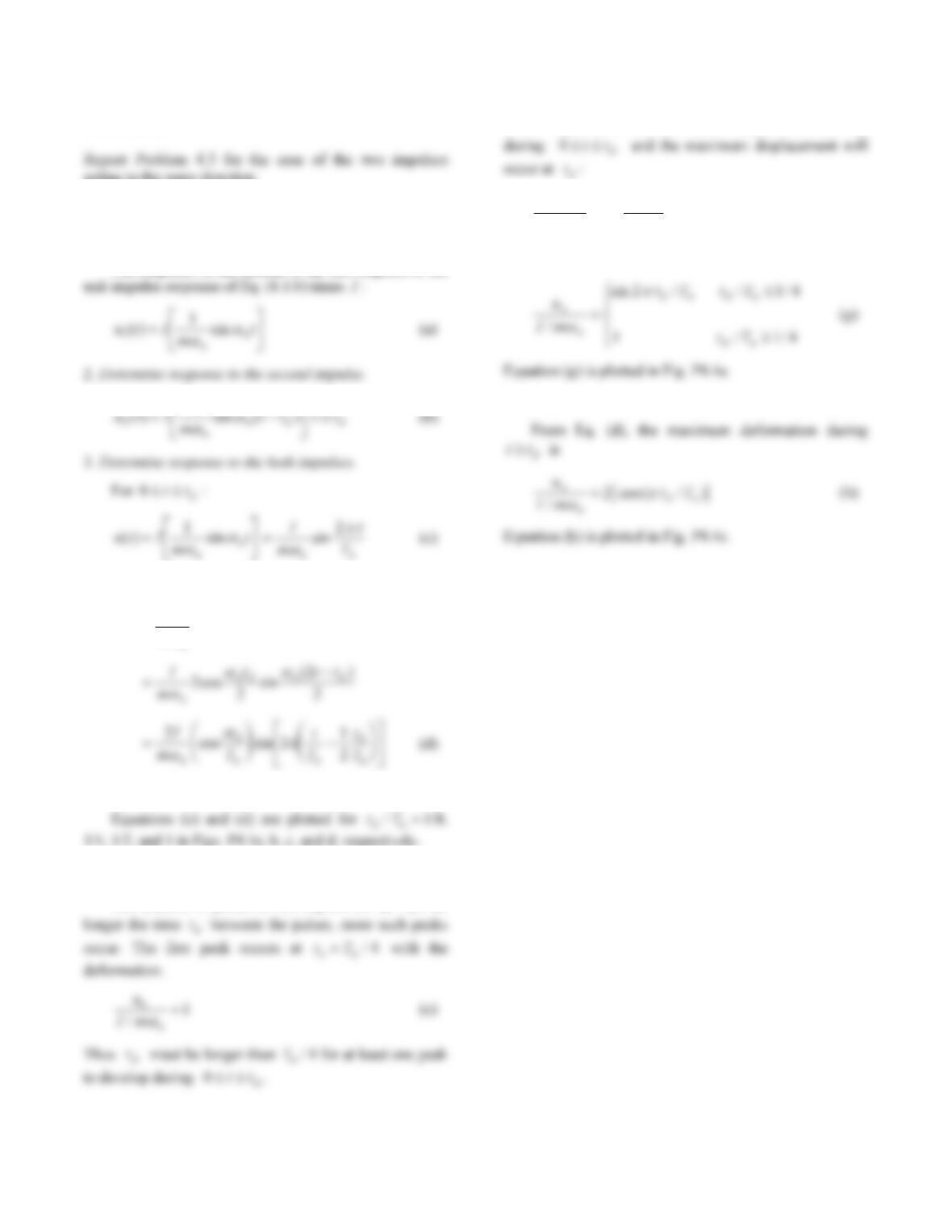
Equation (i) is plotted tT
dn
/ in Fig. P4.3f to obtain the
response spectrum.
00.511.52
1.5
n
tT
dn
Overall maximum
7
Problem 4.4
acting in the same direction.
Solution:
1. Determine response to the first impulse.
The response of the system to the first impulse is the
1
For tt
d
:
ut I
mttt
n
nnd
() [sin sin ( )]
4. Plot displacement response.
5. Determine maximum response during 0tt
d.
The number of peaks in u(t) depend on tT
dn
/; the
If td is shorter than Tn/4no peak will develop
n
d
n
d
T
t
mI
tu
2
sin
/
)( (f)
The maximum deformation during 0tt
d is
6. Determine maximum response during tt
d
.
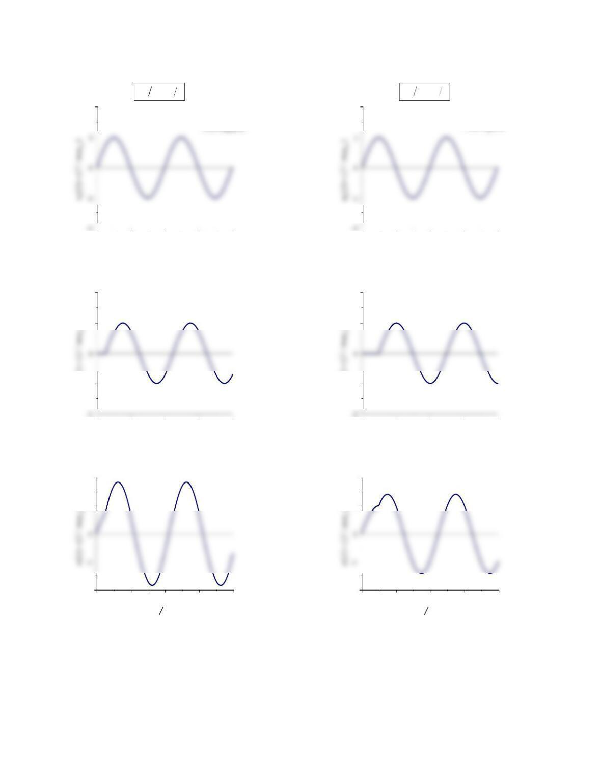
8
00.511.52
2
tT
dn
18
First impulse
00.511.52
-1
1
2Second impulse
ut I m n
() ( / )
2
00.511.52
-2
1
2
tT
n
Both impulses
Figure P4.4a
00.511.52
2
tT
dn
14
First impulse
00.511.52
-1
1
2
Second impulse
ut I m n
() ( / )
2
0 0.5 1 1.5 2
-2
1
2
tT
n
Both impulses
Figure P4.4b
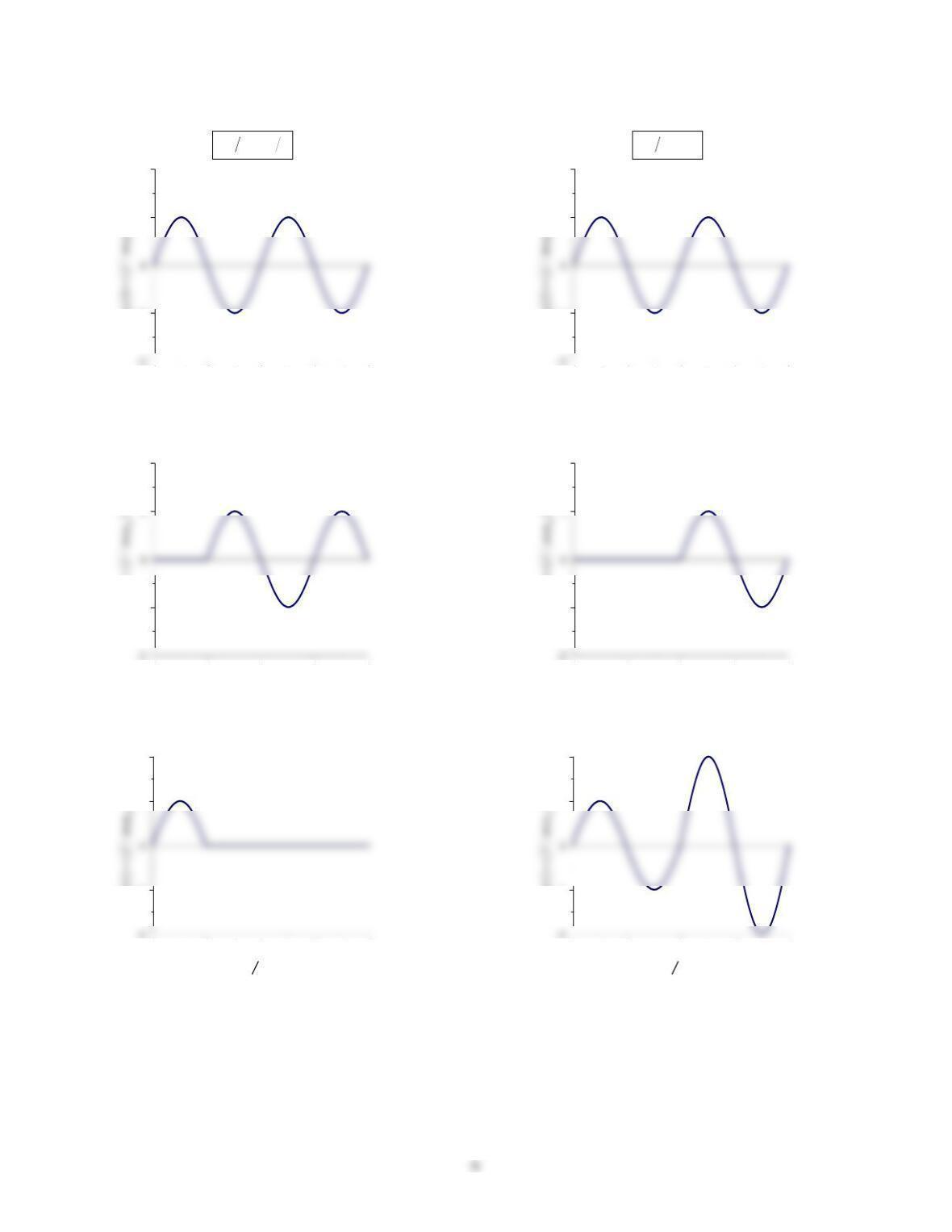
00.511.52
-1
1
2
ut I m n1() ( / )
tT
dn12
First impulse
00.511.52
-1
2
Second impulse
ut I mn
() ( / )
2
00.511.52
-1
1
2
utIm
() ( / )
tT
n
Both impulses
Figure P4.4c
00.511.52
-1
1
2
ut I mn1() ( / )
tT
dn1
First impulse
00.511.52
-1
2
Second impulse
ut I m n
() ( / )
2
0 0.5 1 1.5 2
-1
1
2
utIm
() ( / )
tT
n
Both impulses
Figure P4.4d
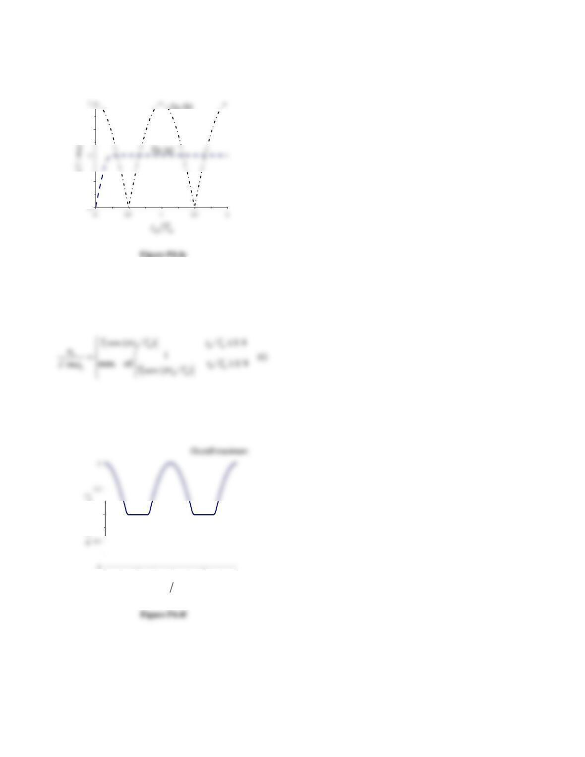
10
0.5
1.5
n
uIm
o
7. Determine the overall maximum response.
From Eqs. (g) and (h), the overall maximum response
is given by
Equation (i) is plotted tT
dn
/ in Fig. P4.4f to obtain the
response spectrum.
00.511.52
1
tT
dn
n
(/
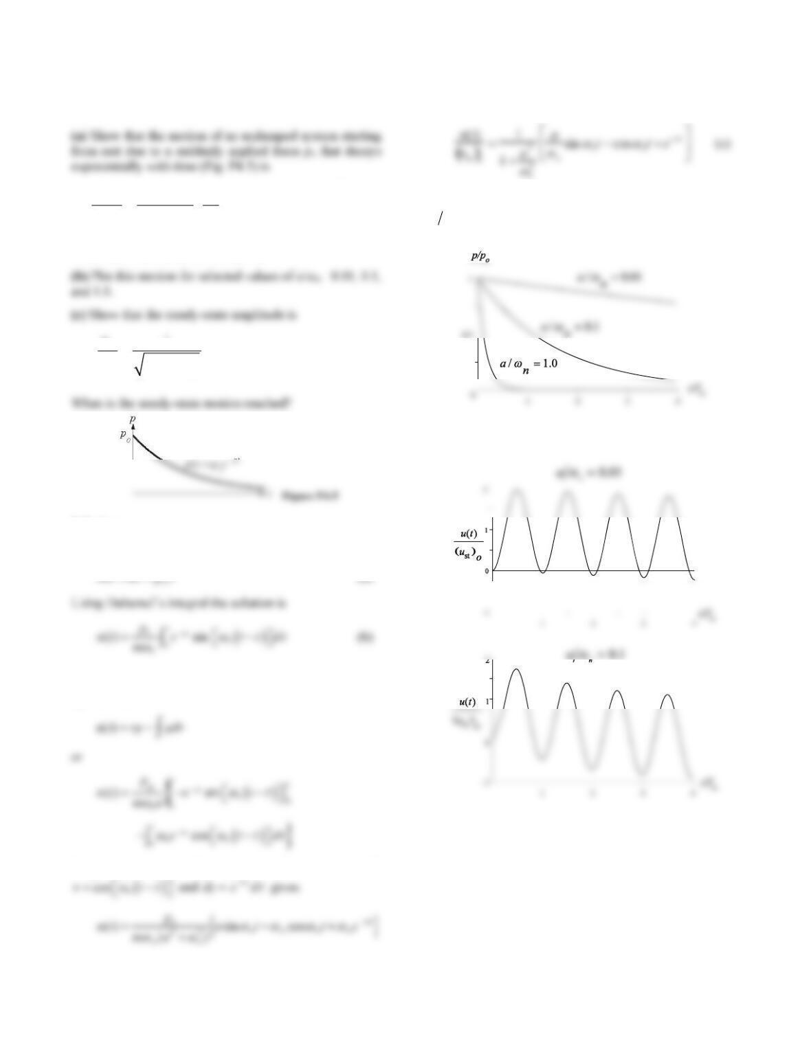
11
Problem 4.5
22
st
1sin cos
() 1 /
at
nn
onn
ut atte
ua
Note that a has the same units as ωn.
22
st
1
(1/
o
n
u
ua
Solution:
(a) The equation of motion is
at
(a)
Integrate by parts letting
sin n
vt
and
dy ea
d
:
Integrating again by parts, this time with
Written in terms of
o
ust , the displacement response is
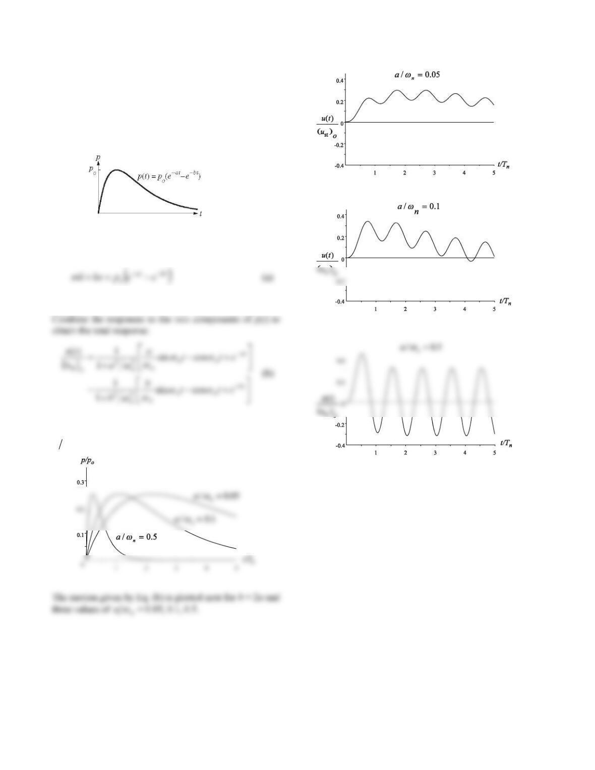
(b) The force p(t)poe
a
t
is plotted for three values of
n
a
:
The motion given by Eq. (c) is plotted next.
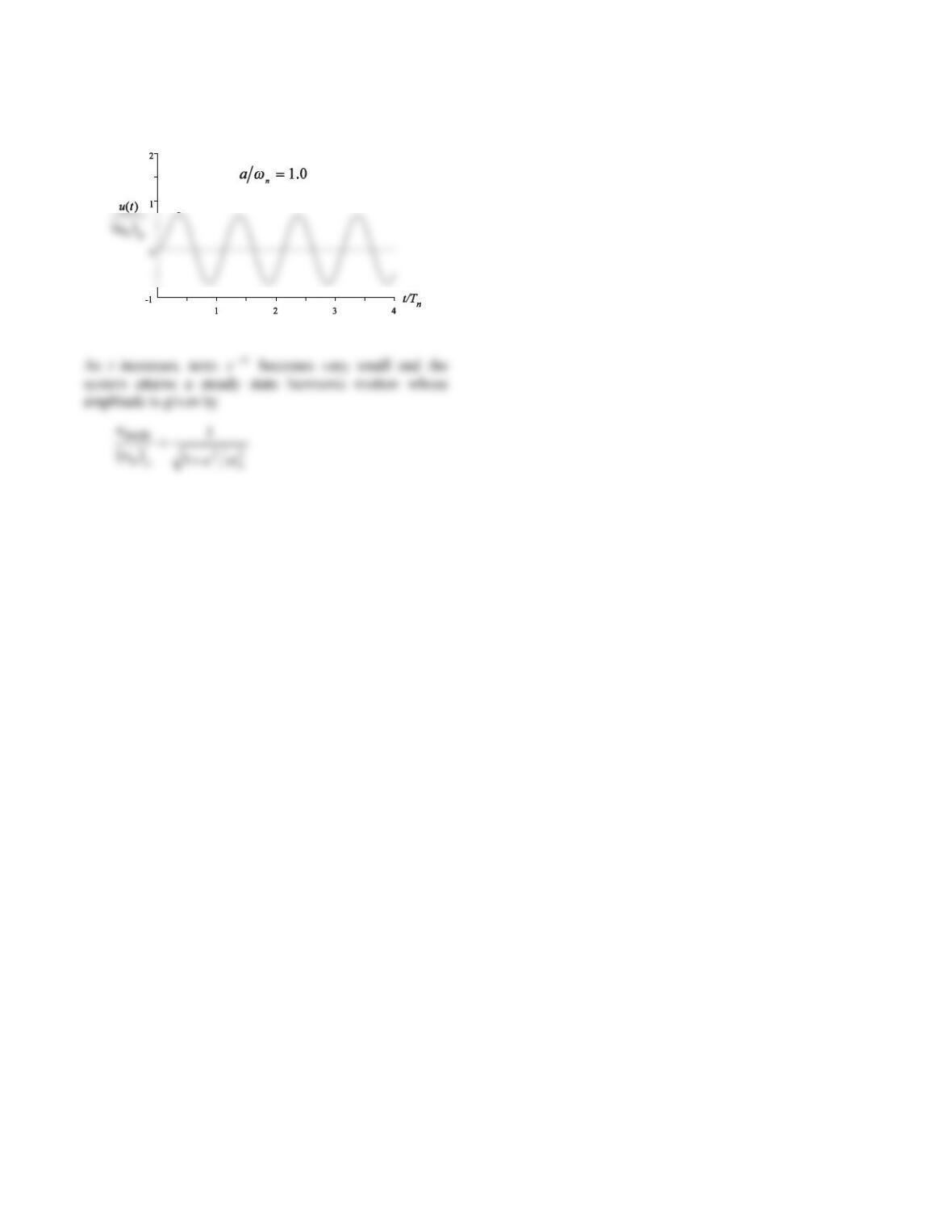
12
13
Problem 4.6
(a) Determine the motion of an undamped system starting
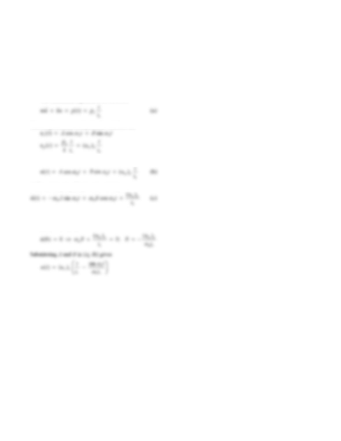
from rest due to the force p(t) shown in Fig. P4.6; b > a.
(b) Plot the motion for b = 2a for three values of
a/ωn = 0.05, 0.1, and 0.5.
Figure P4.6
Solution:
(a) The equation of motion is
The response to each exponential function is given by an
expression of the form in Eq. (c) of Problem 4.5.
(b) The force p(t) is plotted for b = 2a and three values of
an
.
14
Problem 4.7
Using the classical method for solving differential
equations, derive Eq. (4.4.2), which describes the
response of an undamped SDF system to a linearly
increasing force; the initial conditions are u(0) = (0) = 0.
Solution:
The differential equation to be solved is
The complimentary and particular solutions are
t
A
t
t
The complete solution is
Differentiating Eq. (b) gives the velocity
The constants A and B are determined from the initial
conditions
u
A
()00 0
15
Problem 4.8
An elevator is idealized as a weight of mass m supported
by a spring of stiffness k. If the upper end of the spring
begins to move with a steady velocity ν, show that the
distance ut that the mass has risen in time t is governed by
the equation
m t + kut = kvt
If the elevator starts from rest, show that the motion is
ut(t) = νt −
sin ωnt
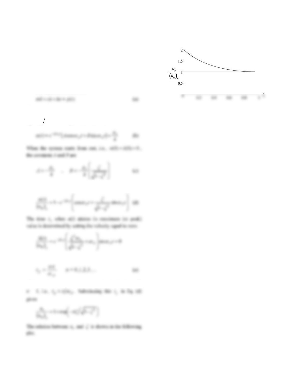
Plot this result.
Solution:
us
= vt
Free body diagram
Dynamic equilibrium gives
The general solution of the differential equation is
Impose initial conditions: ut()00 and ()ut00:
uA
t
()00 0
Substituting for A and B in Eq. (b) gives
Equation (c) is written as
01234
0
1
2
3
4
vTn
utt
( )
n
T
t
16
Problem 4.9
(a) Determine the maximum response of a damped SDF
system to a step force.
(b) Plot the maximum response as a function of the
damping ratio.
Solution:
The equation of motion is
The complementary solution is given by Eq. (f) in
Derivation 2.2 in the book and the particular solution is
upk
po
. Then the general solution is
Then Eq. (b) becomes
t
or
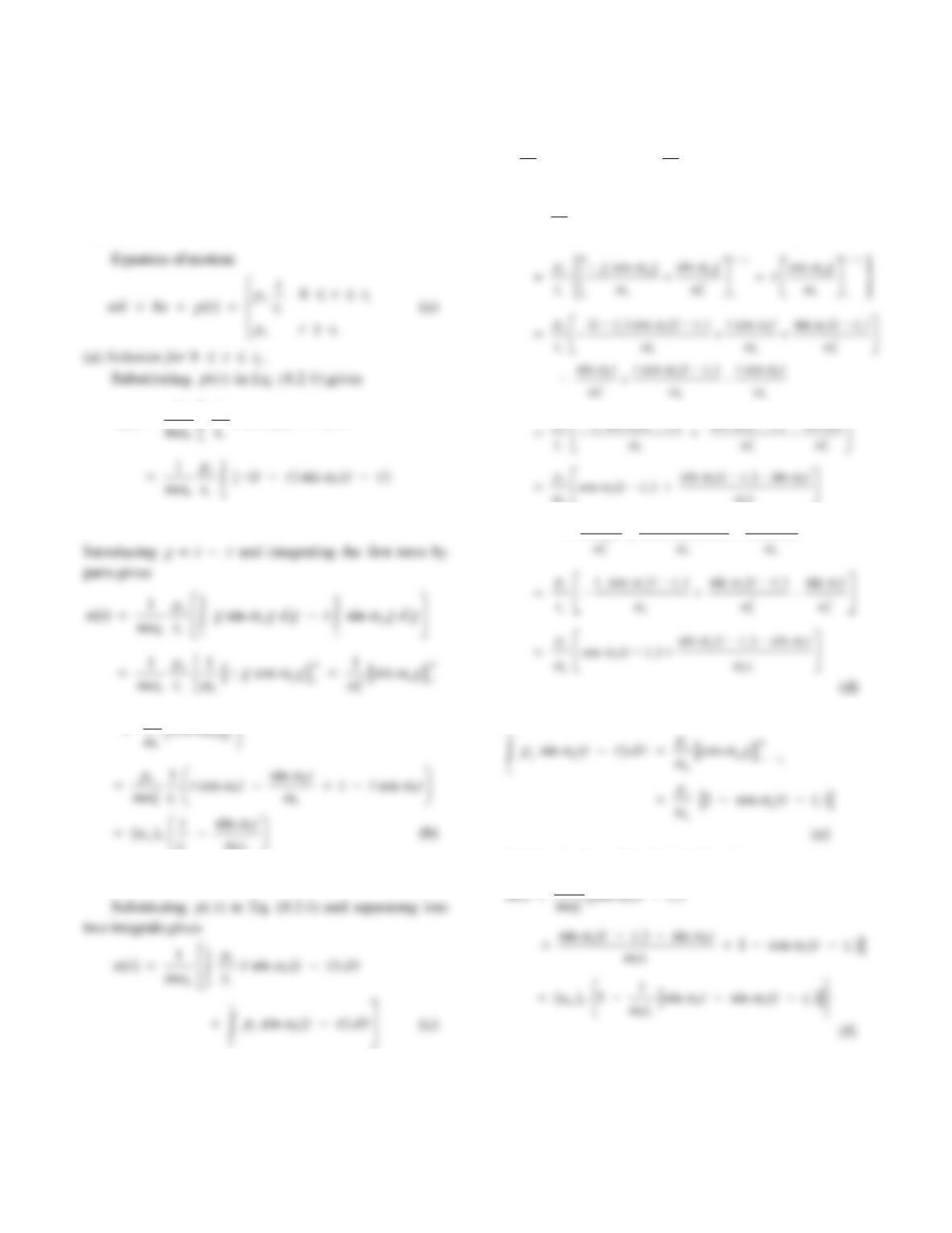
The maximum response occurs at
t
p given by Eq. (e) with
17
Problem 4.10
The deformation response of an undamped SDF system to
a step force having finite rise time is given by Eqs. (4.5.2)
and (4.5.4). Derive these results using Duhamel’s integral.
Solution:
1
() sin ( )
sin ( )]
t
o
n
n
p
ut t d
ttd
t
0
t
rnr
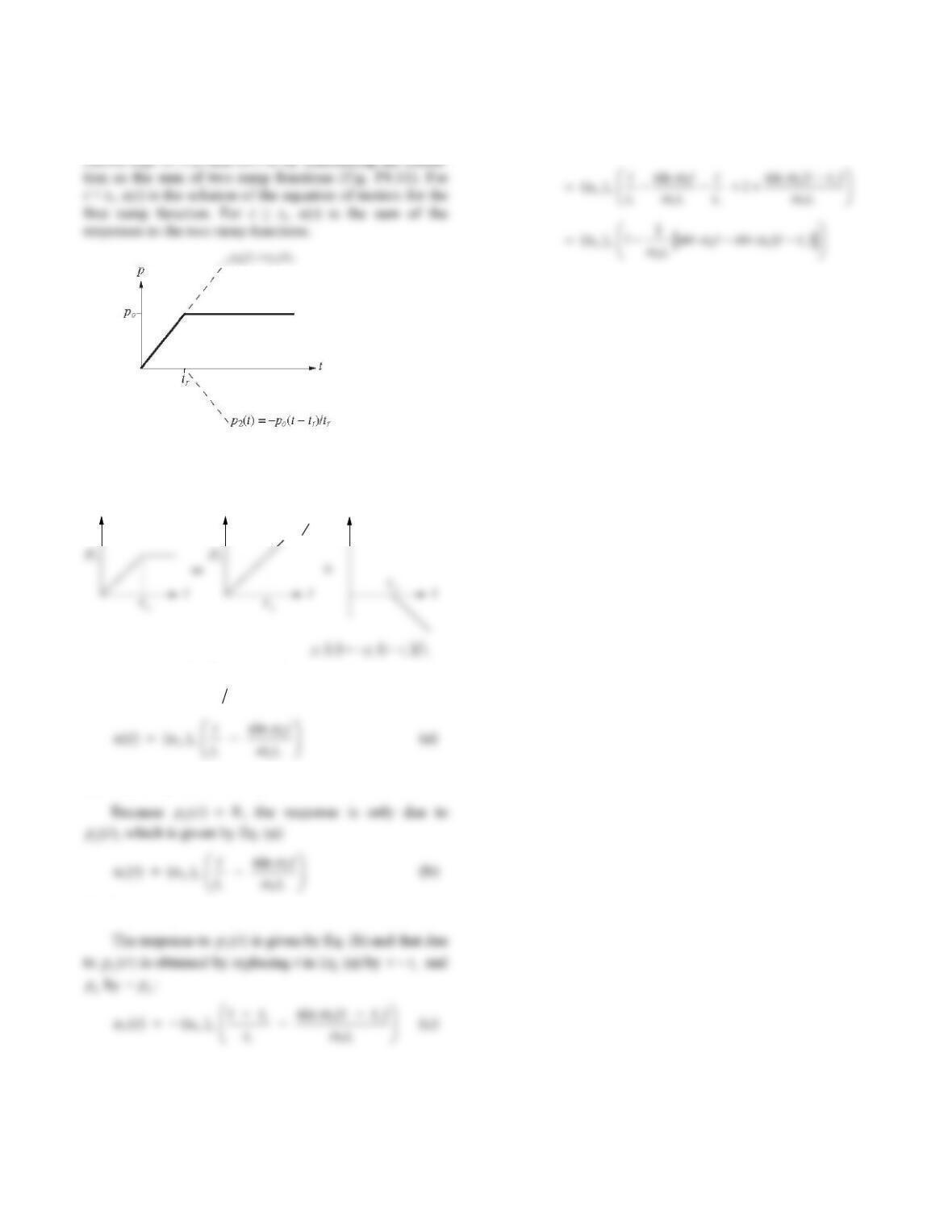
(b) Solution for
t
t
r
.
The first integral in Eq. (c) is
0
sin ( ) ( ) sin
r
rtt
t
oo
nn
rr
t
pp
td t d
tt
sin sin
rr
tt tt
o
nn
rtt
pdt d
t
cos ( ) sin ( ) sin
nnr
pt tt tt t
sin cos ( ) cos
nnr n
tt tt t t
The second integral in Eq. (c) is
Substituting Eqs. (d) and (e) in Eq. (c) gives
o
p
r
18
Problem 4.11
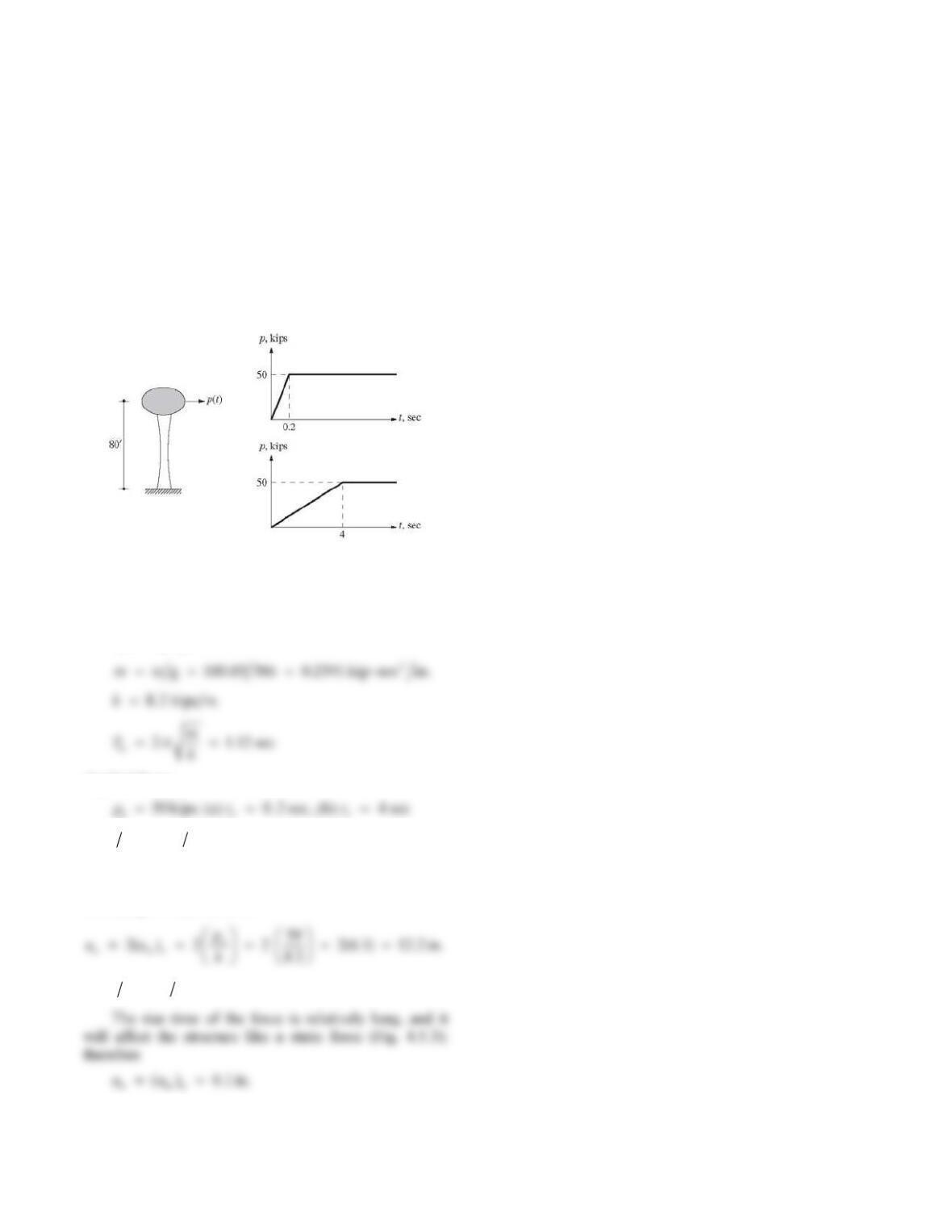
Figure P4.11
Solution:
pt( )
t( )
p1t( )
p2
t
( )
p1po
=tr
t
Equation (4.5.2) gives the response to a ramp
function p
t
p
t
t
o
r
() ( ):
(a) Response for 0
t
t
r
.
t
t
(b) Response for
t
t
r
.
t
t
The total response is the sum of Eqs. (b) and (c):
12
() () ()
ut u t u t
19
Problem 4.12
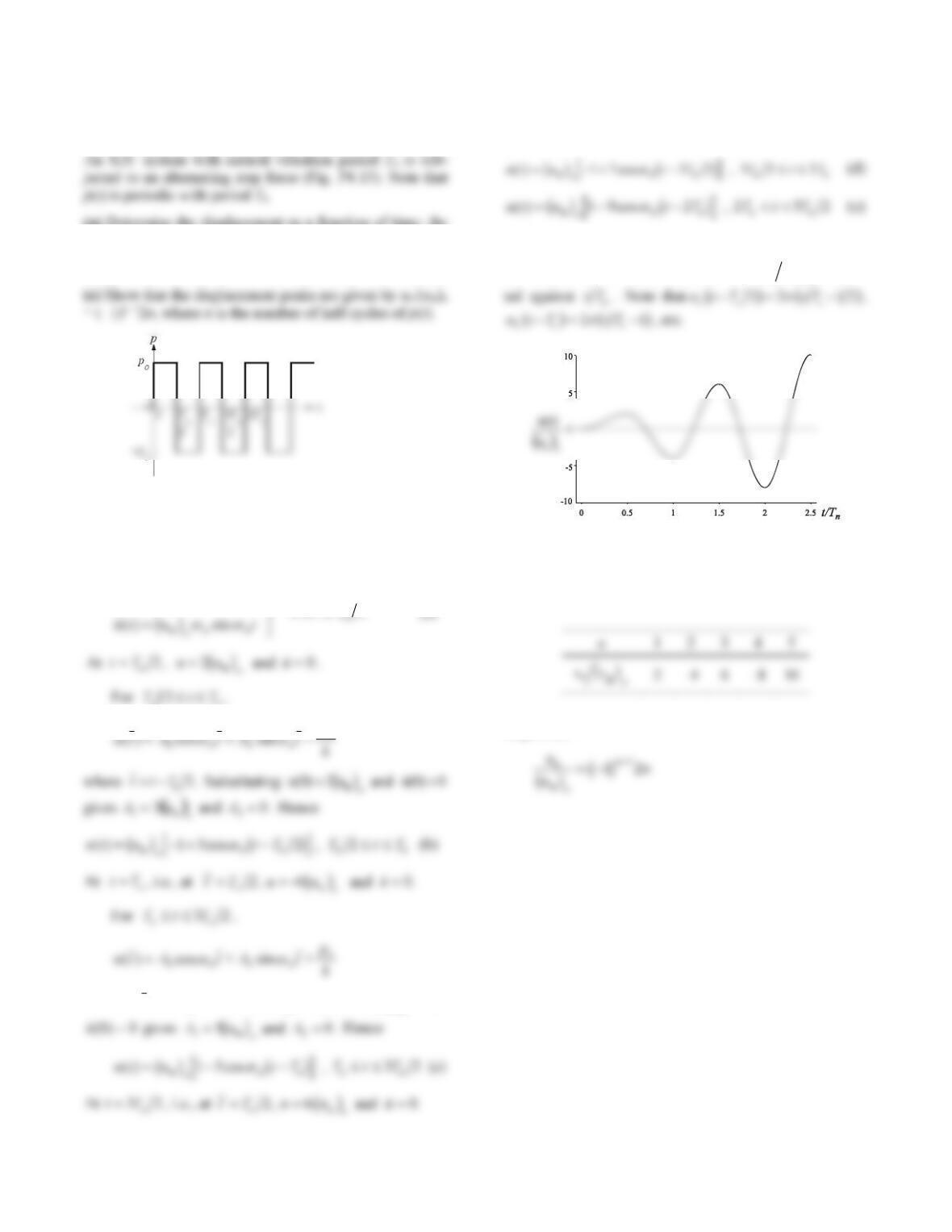
The elevated water tank of Fig. P4.12 weighs 100.03 kips
when full with water. The tower has a lateral stiffness of
8.2 kips/in. Treating the water tower as an SDF system,
estimate the maximum lateral displacement due to each of
the two dynamic forces shown without any “exact”
dynamic analysis. Instead, use your understanding of how
the maximum response depends on the ratio of the rise
time of the applied force to the natural vibration period of
the system; neglect damping.
Figure P4.12
Solution:
System properties:
Applied force:
r
r
(a) tT
r
n0 2 1 12 0 179.. .
The rise time of the force is relatively short, and the
structure will “see” this excitation as a suddenly applied
force (Fig. 4.5.3); therefore
(b) tT
r
n4 1 12 3 57..
20
Problem 4.13
(a) Determine the displacement as a function of time; the
initial conditions are u(0) = (0) = 0.
(b) Plot the response.
Figure P4.13
Solution:
(a) Response results.
We have from Eq. (4.3.2)
ut u t
on
() cos
U
|
st
bgb g
1
02
n2
n,
p
o
where n
Ttt =. Substituting uu
o
()04 st
bg
and
In a similar manner the following results can be
obtained:
(b) Response plot.
From Eqs. (a), (b), (c), (d), and (e) ut u o
() st
bg
is plot-
(c) Peak values.
The displacement peaks un at the end of n half cycles
of applied force are
In general,