PROBLEM 4.47
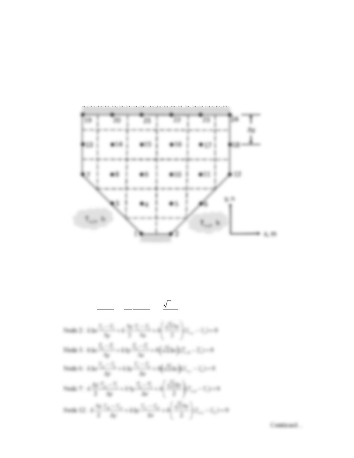
KNOWN: Square channels of known dimension, evenly spaced along centerline of plate of known
thickness and thermal conductivity. Hot and cold fluids with known temperatures and heat transfer
coefficients flowing through alternate channels. N = 50 channels. Use ∆x = ∆y = 5 mm.
FIND: Maximum and minimum temperatures within plate. Heat transfer rate per unit plate length from
hot to cold fluid.
SCHEMATIC:
ASSUMPTIONS: (1) Steady-state conditions, (2) Uniform properties, (3) No internal heat generation,
(4) Two–dimensional conduction.
ANALYSIS: The discretized solution domain is shown in the schematic. The finite difference equations
are:
41 21
,1
2
Node 1: ( ) 0
22
h
TT TT
yx
kx k h T T
yx
∞
−−
∆∆
∆ + + −=
∆∆
PROBLEM 4.47 (Cont.)
19 13 14 13 7 13
Node 13: 0
22
TT TT TT
xx
k ky k
yx y
−−−
∆∆
+∆ + =
∆∆∆
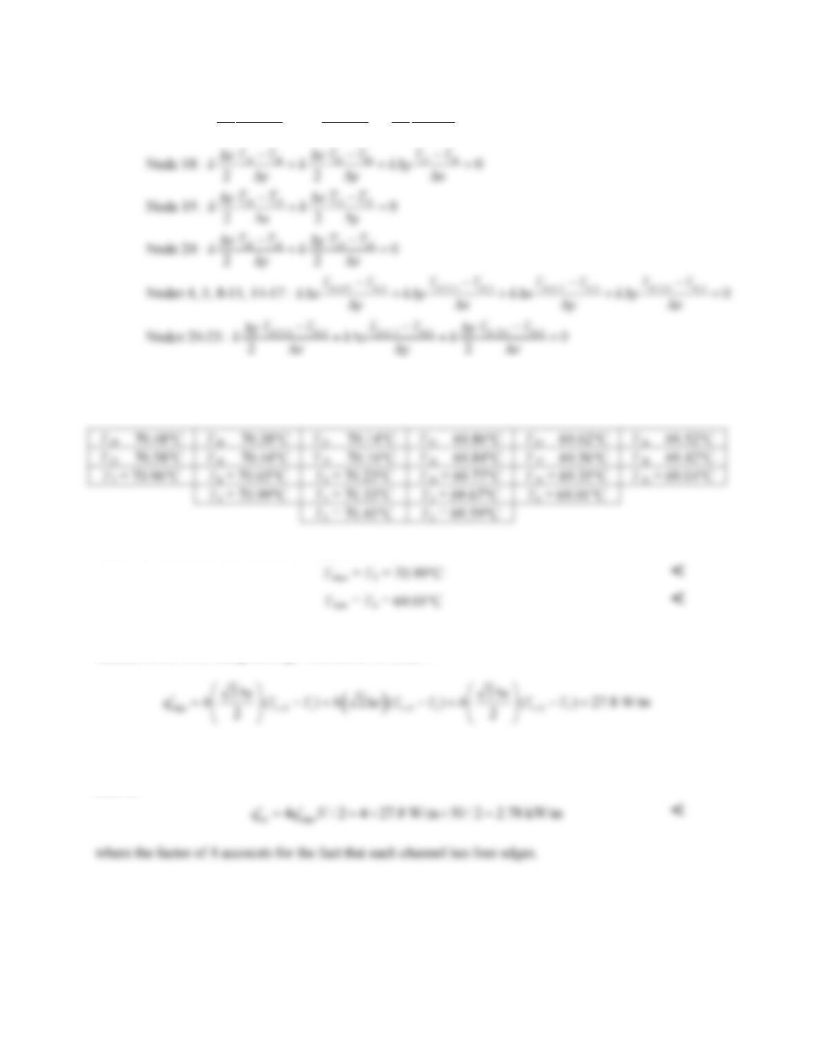
Solving the preceding equations for k = 14 W/m⋅K, h = 40 W/m2⋅K, T∞,h = 120°C, T∞,c = 20°C, ∆x = ∆y
= 5 mm yields the nodal temperatures shown below.
Hence the maximum and minimum temperatures are:
We elect to calculate the heat rate per unit length by first evaluating the convection rate from a hot
channel to the solid along the edge with nodes 1, 3, and 7.
Under steady-state conditions, with the plate insulated, all of the heat that is transferred from the hot fluid
to the solid must then enter the cold fluid. For N = 50 channels, the total heat transfer rate from hot to cold
fluid is
COMMENTS: The heat rate can be evaluated in several ways. For example,
edge
q′
may be determined by
calculating the convection loss to the cold fluid. Alternatively,
edge
q′
may be evaluated by calculating the
conduction rate perpendicular to the vertical centerline of the domain.
PROBLEM 4.48
KNOWN: Volumetric heat generation in a rectangular rod of uniform surface temperature.
FIND: (a) Temperature distribution in the rod, and (b) With boundary conditions unchanged, heat
generation rate causing the midpoint temperature to reach 600 K.
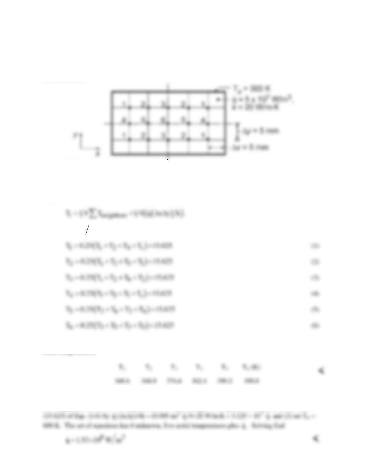
SCHEMATIC:
ASSUMPTIONS: (1) Steady-state, two-dimensional conduction, (2) Constant properties, (3) Uniform
volumetric heat generation.
ANALYSIS: (a) From symmetry it follows that six unknown temperatures must be determined. Since
all nodes are interior ones, the finite-difference equations may be obtained from Eq. 4.35 written in the
form
With
( )
q x y 4k∆∆
= 62.5 K, the system of finite-difference equations is
With Ts = 300 K, the set of equations was written directly into the IHT workspace and solved for the
nodal temperatures,
(b) With the boundary conditions unchanged, the
q
required for T6 = 600 K can be found using the same
set of equations in the IHT workspace, but with these changes: (1) replace the last term on the RHS
PROBLEM 4.49
KNOWN: Flue of square cross section with prescribed geometry, thermal conductivity and
inner and outer surface temperatures.
FIND: Heat loss per unit length from the flue,
q.
′
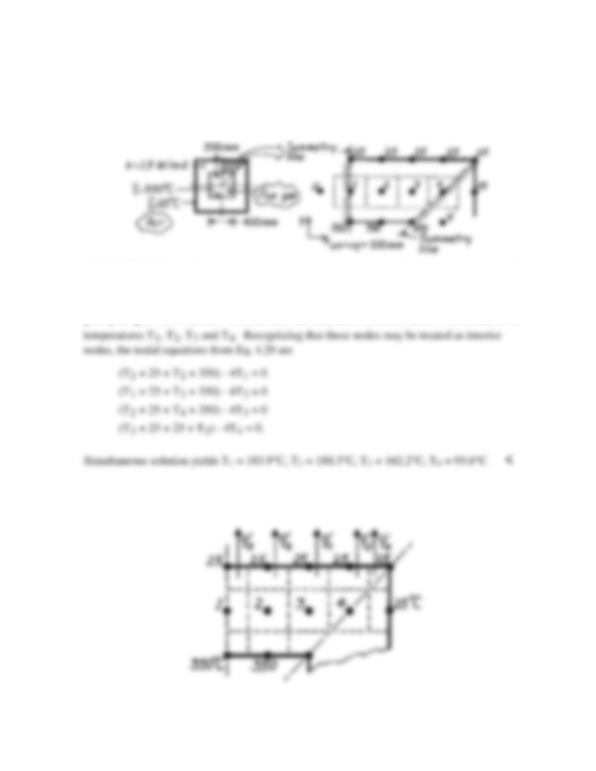
SCHEMATIC:
ASSUMPTIONS: (1) Steady–state, two–dimensional conduction, (2) Constant properties, (3)
No internal generation.
ANALYSIS: Taking advantage of symmetry, the nodal network using the suggested 100 mm
grid spacing is shown above. To obtain the heat rate, we first need to determine the unknown
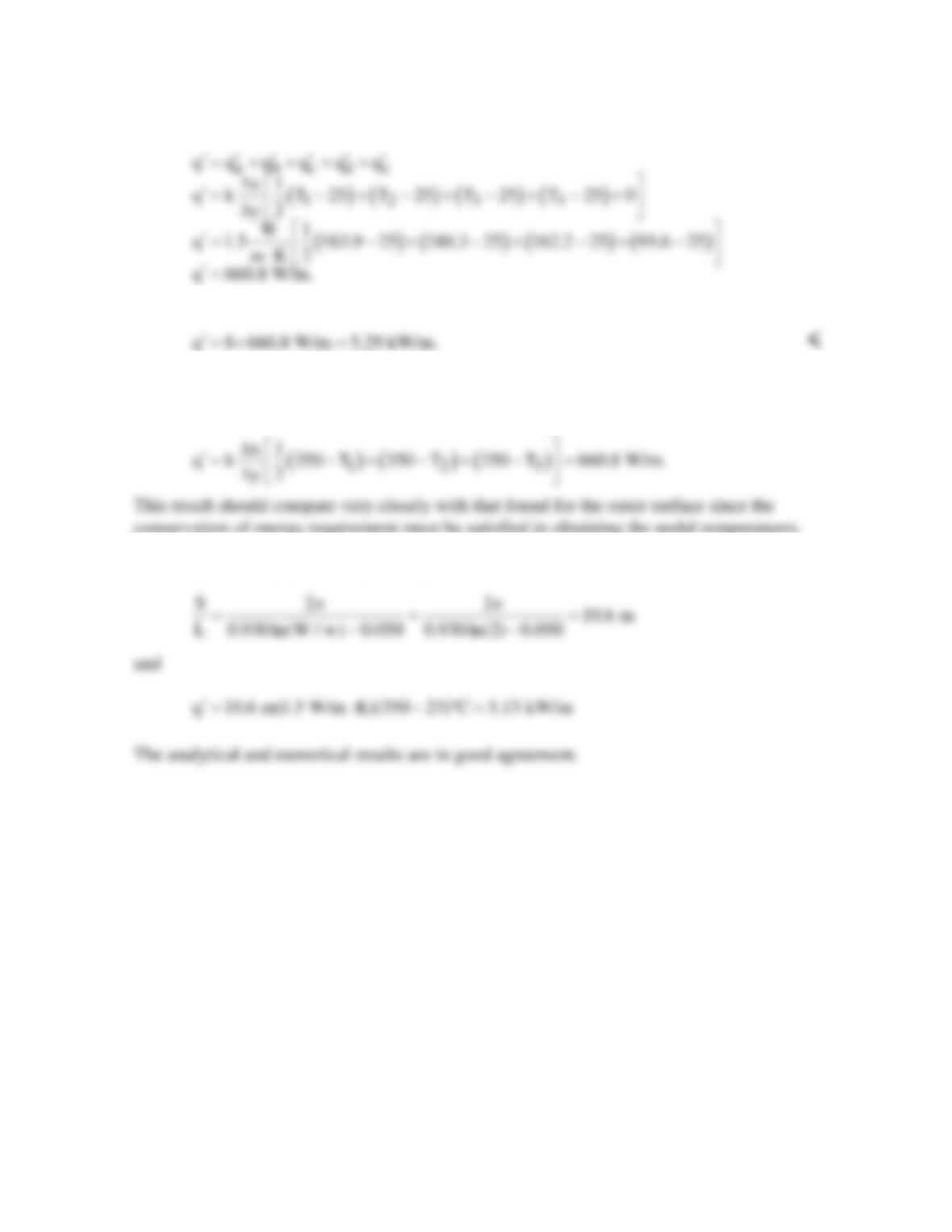
From knowledge of the temperature distribution, the heat rate may be obtained by summing
the heat rates across the nodal control volume surfaces, as shown in the sketch.
Continued…
PROBLEM 4.49 (Cont.)
The heat rate leaving the outer surface of this flue section is,
Since this flue section is 1/8 the total cross section, the total heat loss from the flue is
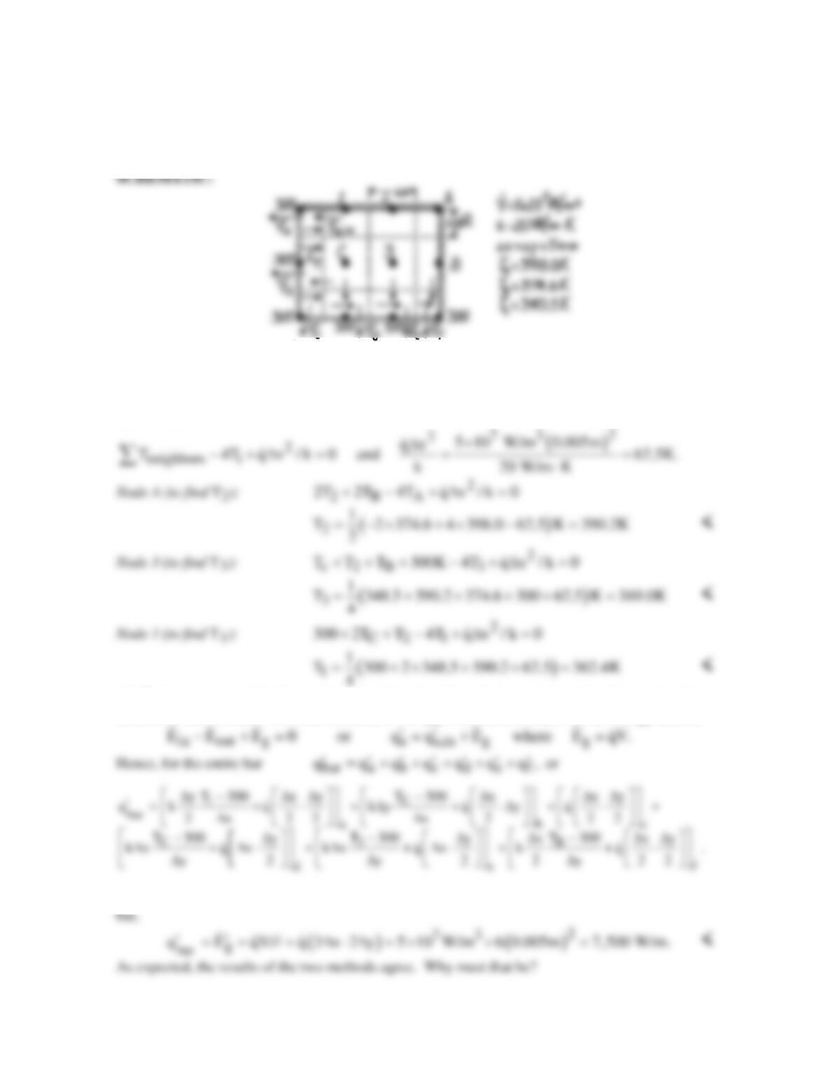
COMMENTS: (1) The heat rate could have been calculated at the inner surface, and from
the above sketch has the form
conservation of energy requirement must be satisfied in obtaining the nodal temperatures.
(2) We may check the numerical result by comparing to the heat loss obtained by using Case
11 of Table 4.1. Here, W/w = 2. Hence,
PROBLEM 4.50
KNOWN: Steady–state temperatures (K) at three nodes of a long rectangular bar.
FIND: (a) Temperatures at remaining nodes and (b) heat transfer per unit length from the bar using
nodal temperatures; compare with result calculated using knowledge of
q.
ASSUMPTIONS: (1) Steady-state, 2-D conduction, (2) Constant properties.
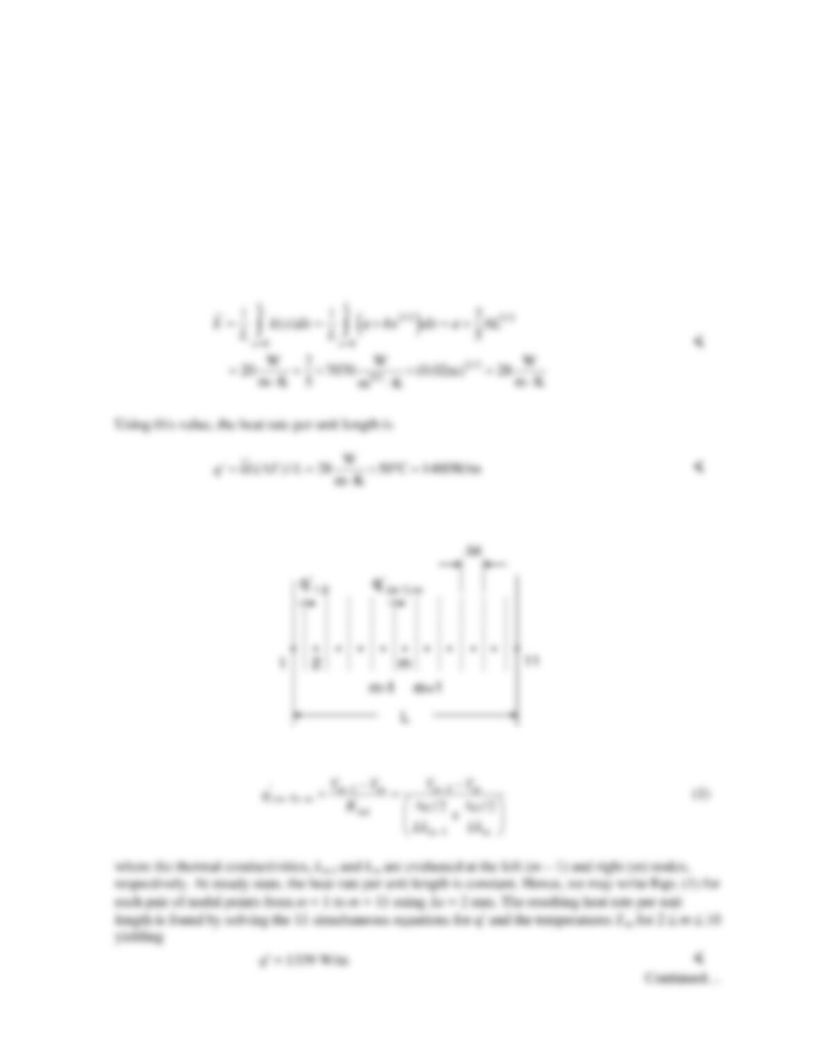
ANALYSIS: (a) The finite-difference equations for the nodes (1,2,3,A,B,C) can be written by
inspection using Eq. 4.35 and recognizing that the adiabatic boundary can be represented by a
symmetry plane.
(b) The heat rate out of the bar is determined by calculating the heat rate out of each control volume
around the 300 K nodes. Consider the node in the upper left-hand corner; from an energy balance
Substituting numerical values, find
bar
q 7,502.5 W/m.
′=
From an overall energy balance on the
PROBLEM 4.51
KNOWN: Dimensions and thermal conductivity distribution within a two-dimensional solid. Applied
boundary conditions.
FIND: (a) Spatially-averaged thermal conductivity and heat rate per unit length based upon this
value, (b) Heat rate per unit length for case 1 boundary conditions and comparison to estimated heat
rate per unit length based upon the spatially-averaged thermal conductivity, (c) Heat rate per unit
length for case 2 boundary conditions and comparison to estimated heat rate per unit length based
upon the spatially-averaged thermal conductivity.
ASSUMPTIONS: Steady-state, one-dimensional heat transfer.
ANALYSIS: (a) The thermal conductivity varies only in the x-direction. Hence,
(b) The nodal network is shown below. Note that the heat transfer is one-dimensional.
For any control surface, Eq. 4.46 may be combined with Fourier’s law and written as
PROBLEM 4.51 (Cont.)
(c) When the applied boundary conditions are changed to those of case 2, we may simply evaluate the
heat transfer from the hot surface to the cool surface by evaluating the heat transfer in 11 different
lanes and summing the results. For the interior lanes the width is ∆x resulting in
and we evaluate the thermal conductivities k1 and k11 at the nodal points, x = 0 and 20 mm,
respectively. The heat rate per unit length of the object is
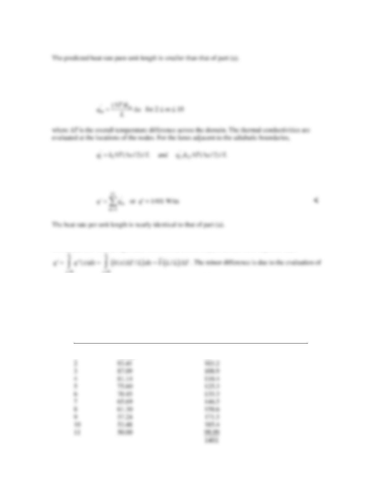
COMMENTS: (1) The agreement between the results of parts (a) and (c) is expected since
00
xx
= =
the thermal conductivity for each lane at the nodal point. The answers would become exactly the same
as the spatial resolution of the numerical solution is increased. (2) In part (b) heat transfer is in the x-
direction, the same direction in which thermal conductivity varies. This reduces heat transfer rates
relative to the value calculated in parts (a) and (c). This is because the resistance expressed in Eq. (1)
is composed of two values in series. The total resistance will be dominated by the higher of the two
individual resistances. (3) Temperatures calculated for case 1 and heat rates in each lane for case 2 are
shown in the table below.
Node or Lane Temperature, °C (case 1) Heat rate per unit length, W/m (case 2)
1 100.00 50
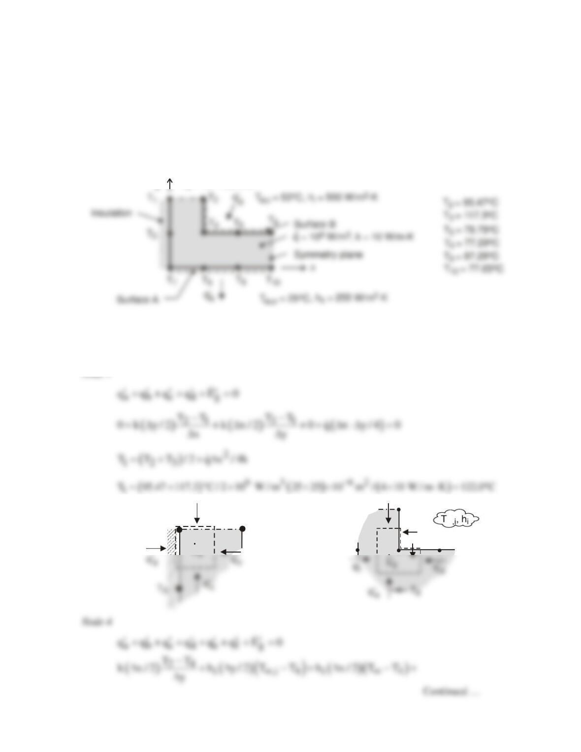
PROBLEM 4.52
KNOWN: Steady–state temperatures at selected nodal points of the symmetrical section of a flow
channel with uniform internal volumetric generation of heat. Inner and outer surfaces of channel
experience convection.
FIND: (a) Temperatures at nodes 1, 4, 7, and 9, (b) Heat rate per unit length (W/m) from the outer
surface A to the adjacent fluid, (c) Heat rate per unit length (W/m) from the inner fluid to surface B,
and (d) Verify that results are consistent with an overall energy balance.
SCHEMATIC:
y
∆
y = x = 25 mm
∆
ASSUMPTIONS: (1) Steady-state, two-dimensional conduction, (2) Constant properties.
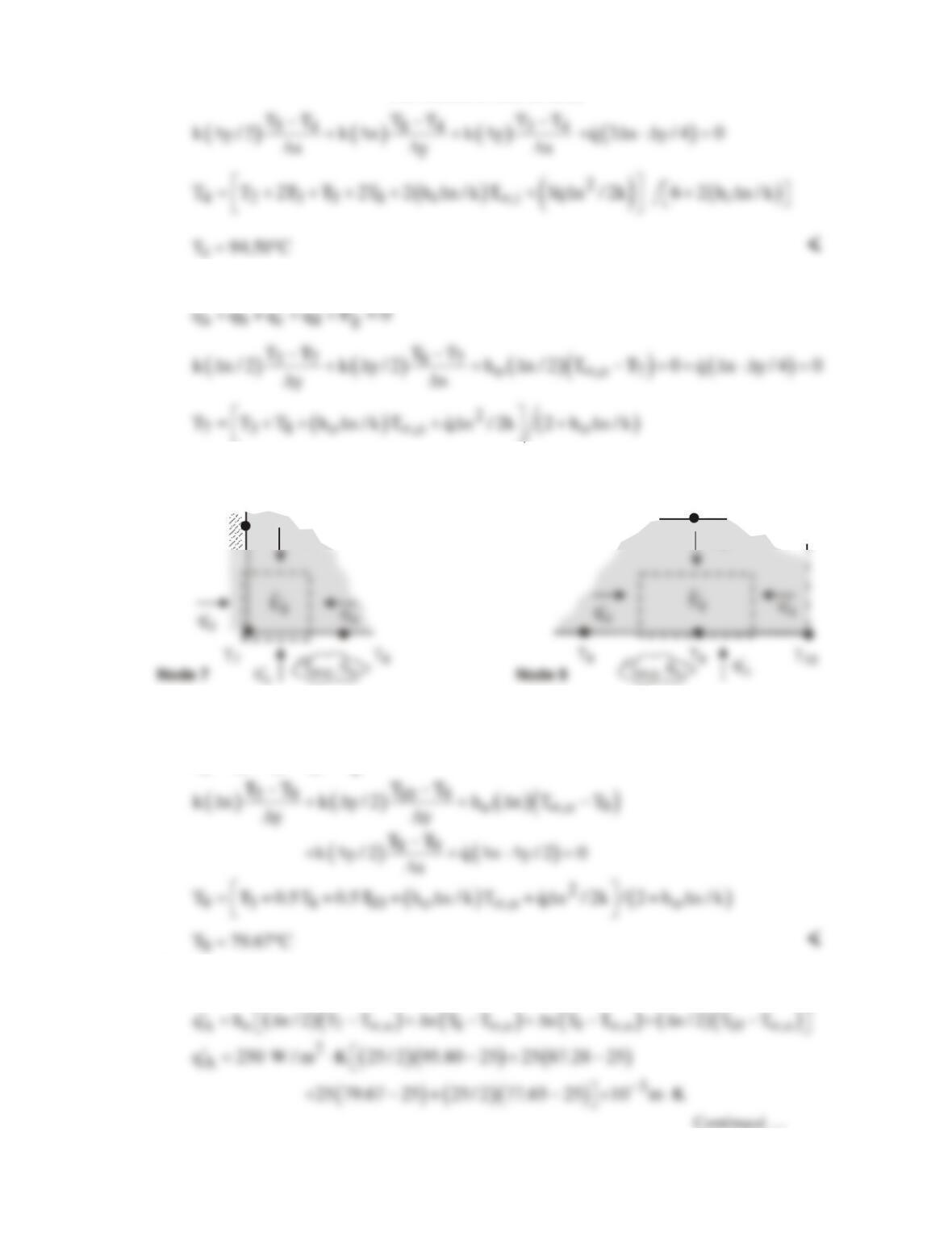
ANALYSIS: (a) The nodal finite-difference equations are obtained from energy balances on control
volumes about the nodes shown in the schematics below.
q’
a
q’
b
q’
c
T
2
T
3
T
5
T
4
o
o
q’
a
T
1
T
2
E’
Node 1 Node 4
PROBLEM 4.52 (Cont.)
Node 7
abcd g
qqqqE 0
7
T 95.80 C= °
<
T
5
q’
a
T
3
q’
a
Node 9
abcd g
qqqqE 0
′′′′ ′
++++ =
T 79.67 C= °
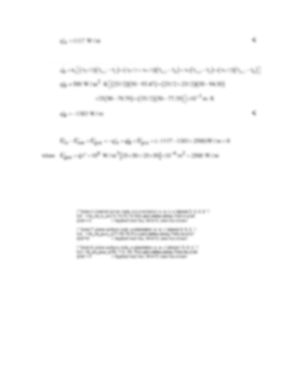
(b) The heat rate per unit length from the outer surface A to the adjacent fluid,
A
q,
′
is the sum of the
convection heat rates from the outer surfaces of nodes 7, 8, 9 and 10.
PROBLEM 4.52 (Cont.)
(c) The heat rate per unit length from the inner fluid to the surface B,
B
q,
′
is the sum of the
convection heat rates from the inner surfaces of nodes 2, 4, 5 and 6.
(d) From an overall energy balance on the section, we see that our results are consistent since the
conservation of energy requirement is satisfied.
COMMENTS: The nodal finite-difference equations for the four nodes can be obtained by using
IHT Tool Finite–Difference Equations | Two–Dimensional | Steady-state. Options are provided to
build the FDEs for interior, corner and surface nodal arrangements including convection and internal
generation. The IHT code lines for the FDEs are shown below.
/* Node 1: interior node; e, w, n, s labeled 2, 2, 3, 3. */
0.0 = fd_2d_int(T1,T2,T2,T3,T3,k,qdot,deltax,deltay)
PROBLEM 4.53
KNOWN: Outer surface temperature, inner convection conditions, dimensions and thermal
conductivity of a heat sink.
FIND: Nodal temperatures and heat rate per unit length.
SCHEMATIC:
ASSUMPTIONS: (1) Steady-state, (2) Two-dimensional conduction, (3) Uniform outer surface
temperature, (4) Constant thermal conductivity.
ANALYSIS: (a) To determine the heat rate, the nodal temperatures must first be computed from the
corresponding finite-difference equations. From an energy balance for node 1,
kk
With nodes 2 and 3 corresponding to Case 3 of Table 4.2,
kk
where the symmetry condition is invoked for node 3. Applying an energy balance to node 4, we
obtain
The interior nodes 5, 6 and 7 correspond to Case 1 of Table 4.2. Hence,
where the symmetry condition is invoked for node 7. With
s
T 50 C, T 20 C,
∞
=°=°
and
T C
so
= 50
T = 15 C, h
o
o
o
20
T C
so
= 50
T = 15 C, h
o
o
o
20
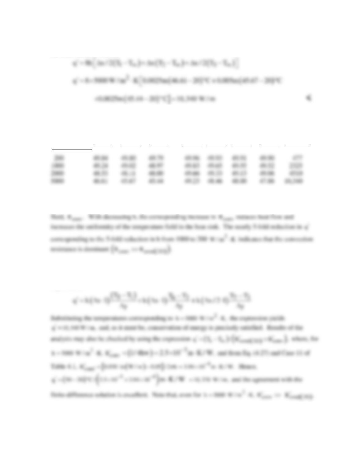
PROBLEM 4.53 (Cont.)
The heat rate per unit length of channel may be evaluated by computing convection heat transfer from
the inner surface. That is,
(b) Since
2
h 5000 W / m K= ⋅
is at the high end of what can be achieved through forced convection,
we consider the effect of reducing h. Representative results are as follows
()
2
h W/m K⋅
( )
1
TC°
( )
2
TC°
( )
3
TC°
( )
4
TC°
( )
5
TC°
( )
6
TC°
( )
7
TC°
( )
q W/m
′
There are two resistances to heat transfer between the outer surface of the heat sink and the fluid, that
due to conduction in the heat sink,
( )
cond 2D ,
R
and that due to convection from its inner surface to the
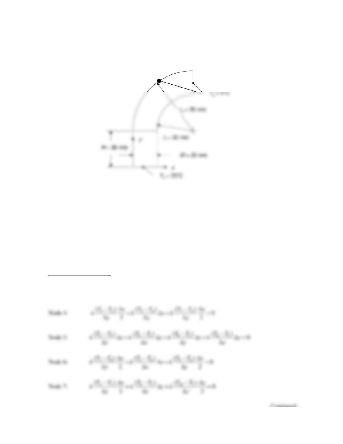
COMMENTS: To check our finite-difference solution, we could assess its consistency with
conservation of energy requirements. For example, an energy balance performed at the inner surface
requires a balance between convection from the surface and conduction to the surface, which may be
expressed as
PROBLEM 4.54
KNOWN: Dimensions of a two-dimensional object with isothermal and adiabatic boundaries.
FIND: Conduction heat transfer rate per unit depth from the hot surface to the cold surface.
SCHEMATIC:
ASSUMPTIONS: (1) Steady–state conditions, (2) Constant properties, (3) No internal generation, (4)
Two–dimensional conduction.
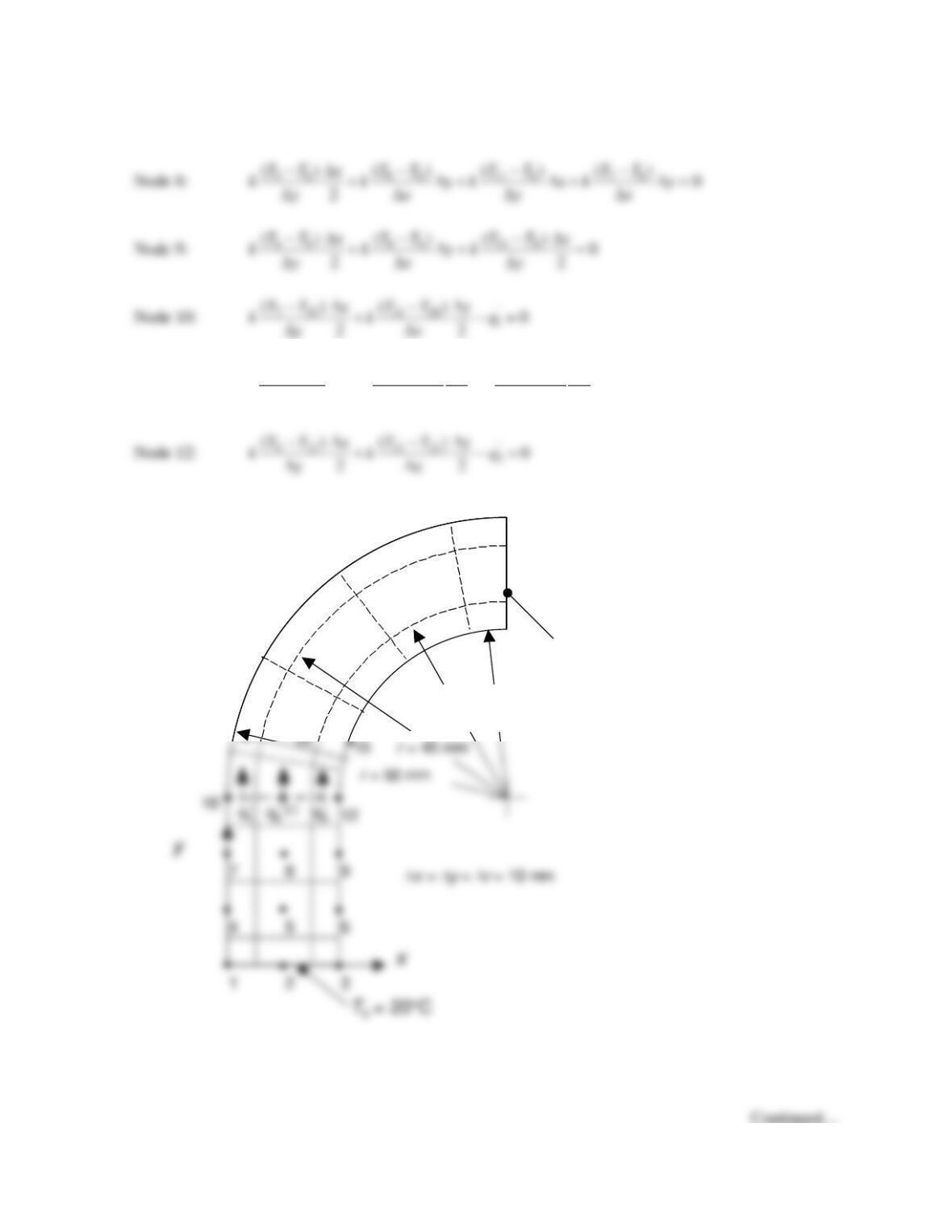
ANALYSIS: We may combine heat fluxes determined from Fourier’s law with expressions for the
size of the control surfaces of the various control volumes to determine the heat rate per unit depth into
each control volume in the discretized domain, which is shown on the next page. Application of
conservation of energy for each control volume yields the expression
in
0E=
. Note that energy
balances for nodes 10, 11, and 12 are included in both the rectangular and cylindrical sub-domains.
These energy balances couple the solutions together.
Rectangular Sub–Domain. For the rectangular sub-domain, application of Fourier’s law in Cartesian
coordinates along with conservation of energy yields the following finite difference equations.
Nodes 1, 2 and 3: T1 = T2 = T3 = Th = 20°C.
Continued…
Problem 4.54 (Cont.)
Node 11:
‘
8 11 10 11 12 11 2
()( ) ( ) 0
22
TT TTy TTy
k xk k q
yx x
− −∆ −∆
∆+ + − =
∆∆ ∆
Tc= 0°C
•
•
•
•
•
•
•
••
•
•
13
16
17
18
19
20
21
22
23
24
r= 30 mm
r = 35 mm
Tc= 0°C
•
•
•
•
•
•
•
••
•
•
13
16
17
18
19
20
21
22
23
24
r= 30 mm
r = 35 mm
Tc= 0°C
•
•
•
•
•
•
•
••
•
•
13
16
17
18
19
20
21
22
23
24
r= 30 mm
r = 35 mm
Problem 4.54 (Cont.)
Cylindrical Sub-Domain. We begin by recalling that Fourier’s law for the cylindrical coordinate
system yields
and the areas through which conduction occurs in the radial direction increase as the radius increases.
Nodes 10, 13, 16, 19, 22, 23 and 24: T10 = T13 = T16 = T19 = T22 = T23 = T24 = Tc = 0°C
Node 15:
12 15 14 15 18 15
()() ()
3.5 0
32 32
TT r TT TT r
k k rk
rr r
φ
φφ
−∆ − −∆
+ ⋅ ∆∆ + =
∆∆ ∆ ∆∆
Node 17:
14 17 18 17 20 17 16 17
( ) ( ) ( )( )
3.5 4.5 0
44
TT TT TT TT
k rk r k rk r
r r rr
φφ
φφ
− − −−
⋅∆ + ⋅ ∆∆ + ∆ + ⋅ ∆∆ =
∆∆ ∆ ∆∆ ∆
φ
Note that energy balances for nodes 10, 11 and 12 are included in both the rectangular and cylindrical
sub-domains. These energy balances couple the solutions for the two sub-domains together.
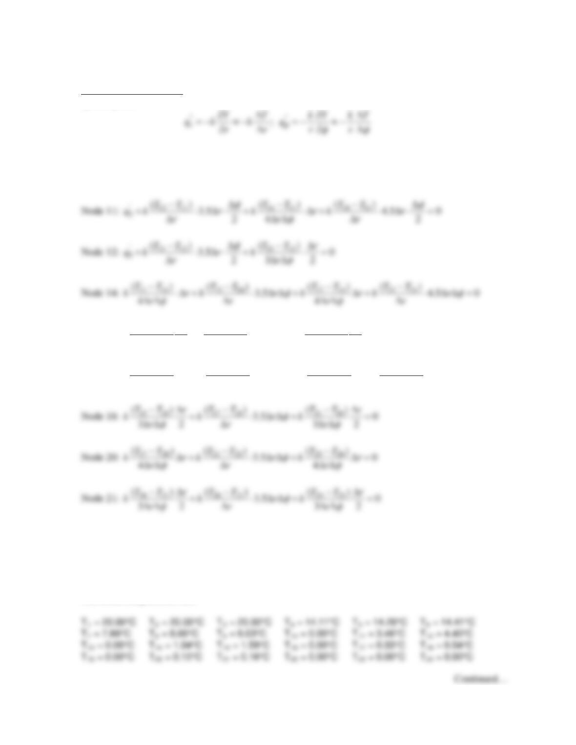
The preceding finite difference equations may be solved simultaneously with the IHT code provided in
the Comment yielding the following temperatures and
‘ 114.5 W/mq=
. <
The nodal temperatures are:
Problem 4.54 (Cont.)
COMMENTS: (1) The IHT code is listed below. For each control volume, we note that
0
in
E=
and
∆y = ∆x, yielding the following energy balances for all but the isothermal nodes.
// Input Parameters
T1 = Th
//Node 2
T2 = Th
//Node 3
T3 = Th
//Node 4
(T1 – T4)/2 + (T5 – T4) + (T7 – T4)/2 = 0
//Node 5
(T2 – T5) + (T6 – T5) + (T8 – T5) + (T4 – T5) = 0
//Node 6
//Node 11
(T8 – T11)+(T10 – T11)/2 + (T12 – T11)/2 – qprime2/k = 0
//Node 12
(T9 – T12)/2 + (T11 – T12)/2 – qprime3/k = 0
//Nodes Common to Both Sub–Domains (Cylindrical)
//Node 10
T10 = Tc
//Node 11
Problem 4.54 (Cont.)
//Node 19
T19 = Tc
//Node 20
(T17 – T20)/4/deltaphi + (T21 – T20)*3.5*deltaphi + (T23 – T20)/4/deltaphi + (T19 – T20)*4.5*deltaphi =
0
PROBLEM 4.55
KNOWN: Dimensions of a tube of non-circular cross section that can be broken into rectangular and
cylindrical sub–domains. Fluid temperature and heat transfer coefficient, external surface temperature
and tube wall thermal conductivity.
FIND: Heat transfer rate per unit length of tube.
SCHEMATIC:
•
•
22
25
•
•
22
25
ASSUMPTIONS: (1) Steady–state conditions, (2) Constant properties, (3) No internal generation, (4)
Two–dimensional conduction.
ANALYSIS: We may combine heat fluxes determined from Fourier’s law with expressions for the
Rectangular Sub–Domain. For the rectangular sub-domain, application of Fourier’s law in Cartesian
Cylindrical Sub-Domain. For the cylindrical sub–domain, application of Fourier’s law in cylindrical
coordinates along with conservation of energy yields the finite difference equations that are listed in
the IHT code included in COMMENT (1).
Continued…
PROBLEM 4.55 (Cont.)
The equations are solved simultaneously to yield the following nodal temperatures in degrees Celsius.
The heat transfer rate per unit depth may be expressed as
COMMENTS: (1) The IHT code is listed below. For each control volume, we note that
0
in
E=
,
yielding the energy balances for the rectangular and cylindrical sub-domains.
ri = 20/1000
Continued…
64.80 55.79
58.89
59.50
60.20
60.82