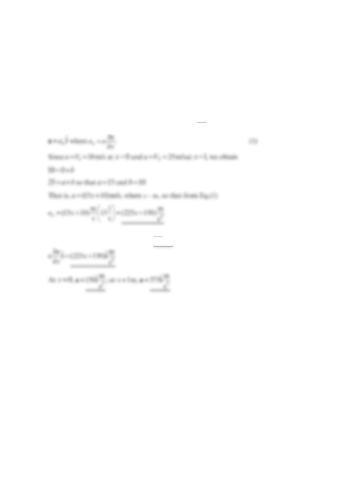
Problem 4.33
As a valve is opened, water flows through the diffuser as shown in the figure below at an
increasing flowrate so that the velocity along the centerline is given by
0(1 ) 1
ct x
uV e
−
== − −
Vi i
, where 0
u, c, and
are constants. Determine the acceleration
as a function of x and t. If =
0
ft
10 s
V
and =5f
t
, what value of c (other than =
0
c) is needed
to make the acceleration zero for any x at 1 st=? Explain how the acceleration can be zero
if the flowrate is increasing with time.
Solution 4.33
∂
=+⋅∇
∂t
V
aVV
with =(,)uuxt
, =0v, and =
0
w
this becomes
ℓ/2
y
x
u = V
0
(1 – e
–ct
)
uu = V
0
(1 – e
–ct
)
1
–
2
If, =0
x
a
for any x at =1
s
t we must have
Problem 4.34
The fluid velocity along the x axis as shown in the figure below changes from m
6
s at point
A
to m
1
8s at point B. It is also known that the velocity is a linear function of distance along the
streamline. Determine the acceleration at points
A
, B, and
C
. Assume steady flow.
Solution 4.34
∂
=+⋅∇
∂t
V
aVV
with =()uux
, =0v, and =
0
w
this becomes
From Eq.(1)
∂
==+
∂⋅
mm
(120 6) 120
sms
u
ux
x
ai i
or
x
0.05 m
CBA
0.1 m
V
A
= 6 m/s
V
B
= 18 m/s
Problem 4.35
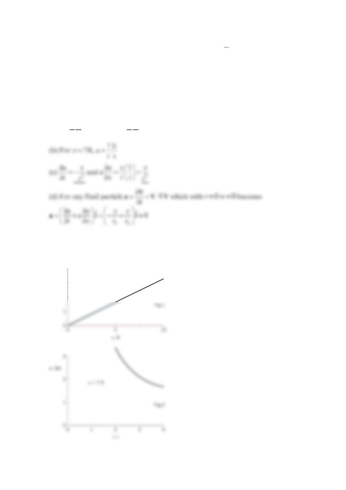
A fluid flows along the x axis with a velocity given by
=
x
t
Vi
, where xis in feet and
t
in
seconds. (a) Plot the speed for ≤≤010ftx and =3st. (b) Plot the speed for =7ftx and
≤≤
2
4st. (c) Determine the local and convective acceleration. (d) Show that the
acceleration of any fluid particle in the flow is zero. (e) Explain physically how the velocity
of a particle in this unsteady flow remains constant throughout its motion.
Solution 4.35
(a) =ft
s
x
utso at =3st, =ft
3s
x
u
(e) The particles flow into areas of higher velocity (see Fig.1), but at any given location, the
velocity is decreasing in time (see Fig.2). For the given velocity field, the local and
convective accelerations are equal and opposite, giving zero acceleration throughout.
2
3
4
u
, fps
t
= 3 s
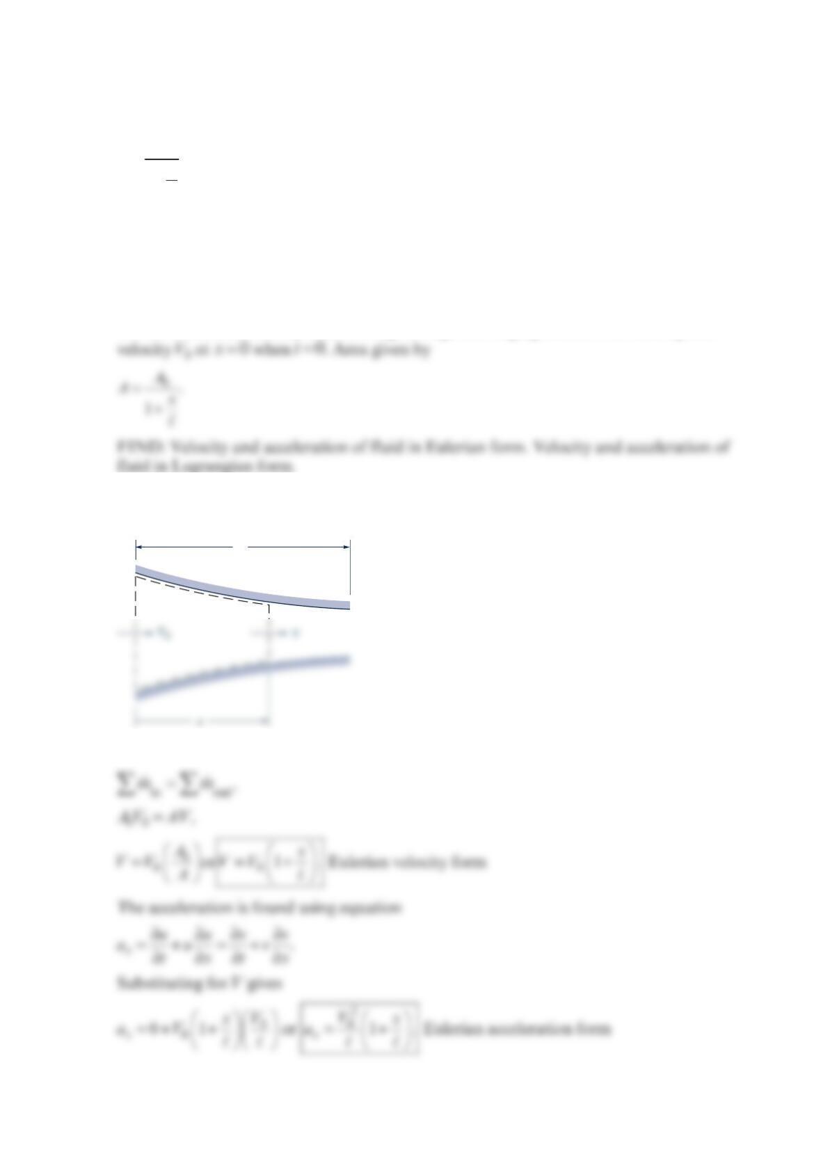
Problem 4.36
A constant-density fluid flows through a converging section having an area
A
given by
=
+
0
1
A
A
x
where 0
A
is the area at =0x. Determine the velocity and acceleration of the fluid in
Eulerian form and then the velocity and acceleration of a fluid particle in Lagrangian
form. The velocity is 0
V
at =0x when 0t=.
Solution 4.36
GIVEN: Constant-density fluid flowing through converging section with area 0
A
and
SOLUTION: Apply the integral continuity equation to the control volume of length x in
the figure.
Since we have a constant density fluid and the control volume is fixed in space, we have
A
ℓ
V
The velocity of a fluid particle is found by first integrating the above equation for
V
Substituting this same expression into the equation for x
a
gives the particle acceleration.
V
Problem 4.37
A hydraulic jump is a rather sudden change in depth of a liquid layer as it flows in an open
channel as shown in the figure below.
In a relatively short distance (thickness =
) the liquid depth changes from 1
z to 2
z, with a
corresponding change in velocity from 1
V to 2
V
. If =
11.20 ft/sV, =
20.30 ft/
s
V, and =0.02 f
t
,
estimate the average deceleration of the liquid as it flows across the hydraulic jump. How
manyg’s deceleration does this represent?
Solution 4.37
∂
=+⋅∇
∂t
V
aVV
so with =()uxVi
, ∂
==
∂
x
u
au
x
ai i
Without knowing the actual velocity distribution, =()uux
, the acceleration can be
approximated as
ℓ
Hydraulic jump
z
1
V
1
V
2
z
2
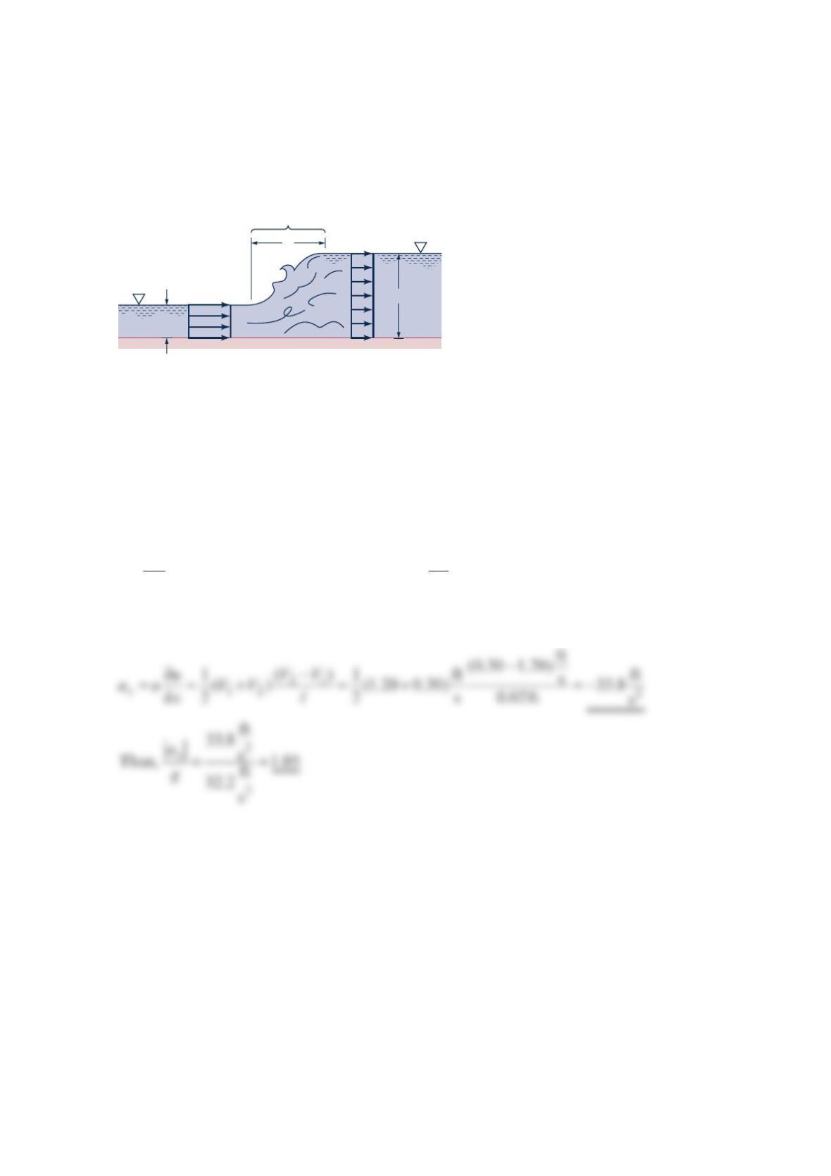
Problem 4.38
A fluid particle flowing along a stagnation streamline, as shown in the figure below, slows
down as it approaches the stagnation point. Measurements of the dye flow indicate that the
location of a particle starting on the stagnation streamline a distance =0.6 ft
s
upstream of
the stagnation point at 0t= is given approximately by −
=0.5
0.6 e t
s
, where
t
is in seconds
and
s
is in feet. (a) Determine the speed of a fluid particle as a function of time, particle ()
V
t,
as it flows along the streamline. (b) Determine the speed of the fluid as a function of
position along the streamline, =()VVs
. (c) Determine the fluid acceleration along the
streamline as a function of position, =(
)
ss
a
as
.
Solution 4.38
(a) With −
=0.5
0.6 e t
s
it follows that 0.5 0.5
particle
ft
0.6( 0.5)e 0.3 s
tt
ds
Ve
dt
−−
== − =−
Stagnation point,
s
= 0
Fluid particle
s
V
Problem 4.39
A nozzle is designed to accelerate the fluid from 1
V to 2
V
in a linear fashion. That is,
=+Vax
b
, where a and b are constants. If the flow is constant with =
110 m/s
V
at =
1
0
x
and =
225m/sVat =
21mx, determine the local acceleration, the convective acceleration,
and the acceleration of the fluid at points (1) and (2).
Solution 4.39
With =+uax
b
, =0v, and =
0
w the acceleration ∂
=+⋅∇
∂t
V
aVV
can be written as
Note: The local acceleration is zero, ∂=
∂0
t
V, and the convective acceleration is
1
Problem 4.40
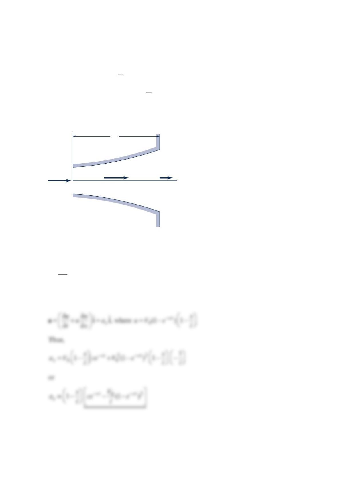
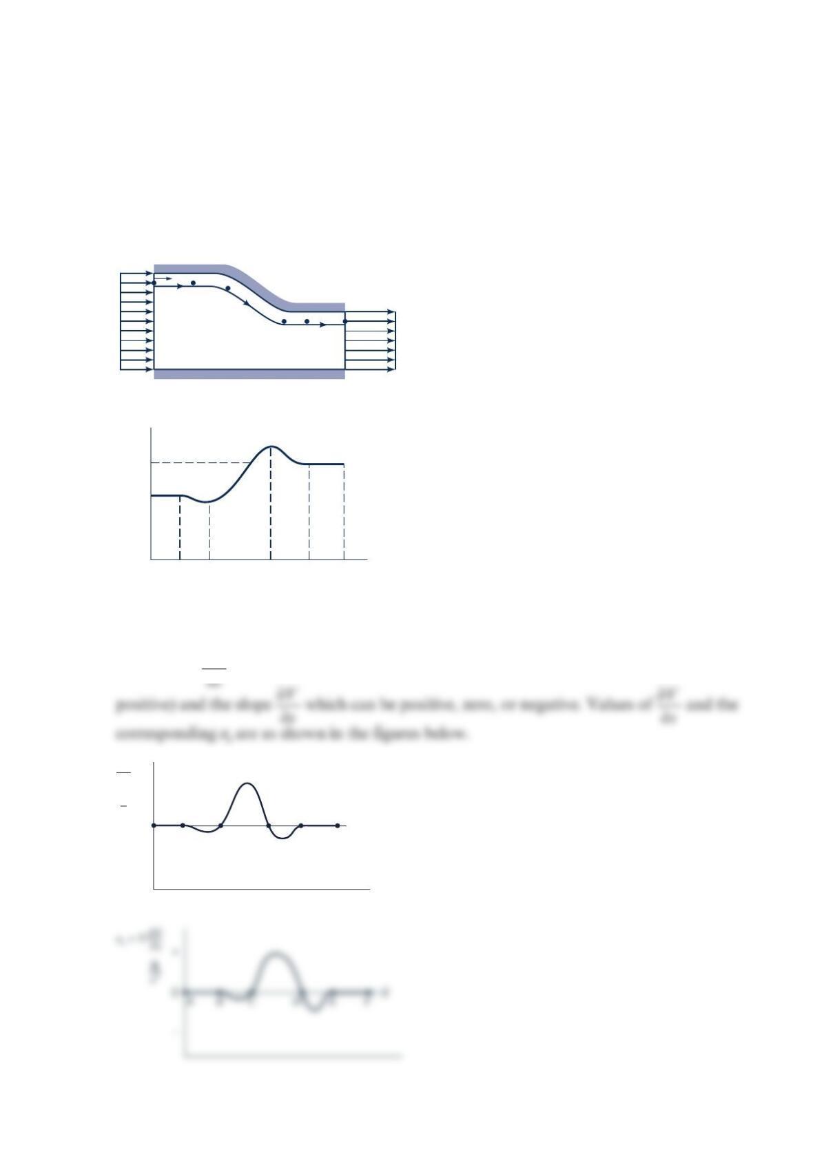
An incompressible fluid flows through the converging duct as shown in the figure (a) below
with velocity 0
V at the entrance. Measurements indicate that the actual velocity of the fluid
near the wall of the duct along streamline −AF is as shown in the figure (b). Sketch the
component of acceleration along this streamline, a, as a function of s. Discuss the
important characteristics of your result.
Solution 4.40
Since ∂
=
s
V
a
Vs, it follows that
s
a
can be obtained from values of
V
(which is always
(
a
)
(
b
)
V
0
1.5
V
0
s
V
DCBAEF
1.5
V
0
V
0
C
D E F
BA
DCBAEF
S
0
–
+
s
∂
V
∂
1
s
a
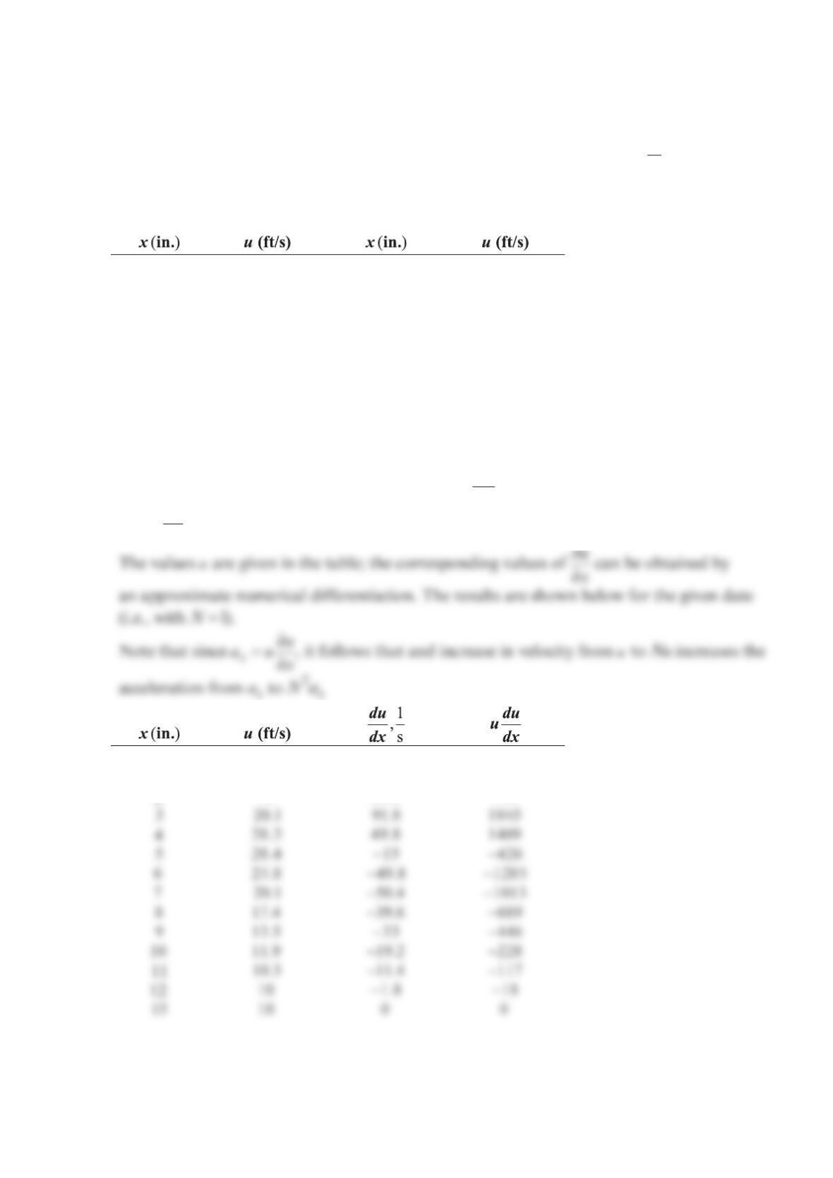
Problem 4.41
Air flows steadily through a variable area pipe with a velocity of =ft
()s
uxVi
, where the
approximate measured values of ()ux are given in the table. Plot the acceleration as a
function of x for ≤≤012 in.x Plot the acceleration if the flowrate is increased by a factor
of N (i.e., the values of
u
are increased by a factor of N) for =2, 4, 10N.
010.0 720.1
110.2 817.4
213.0 913.5
320.1 10 11.9
428.3 11 10.3
528.4 12 10.0
625.8 13 10.0
Solution 4.41
Since =()uux
, =0v, and =
0
w, it follows that ∂
=+⋅∇
∂t
V
aVV
simplifies to =x
aai
where
∂
=
∂
x
u
a
ux (1)
0 10 2.4 24
110.2 18 184
213 59.4 772
1
u
The results are plotted below.
25
30
60
40
80
100
1500
2000
2500
N
= 1
For
N
≠ 1 multiply
ax
by
N2
Problem 4.42
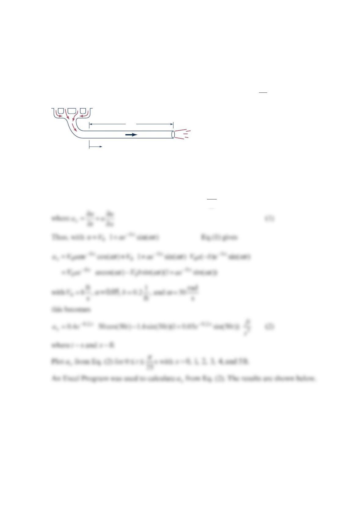
As is indicated in the figure below, the speed of exhaust in a car’s exhaust pipe varies in
time and distance because of the periodic nature of the engine’s operation and the damping
effect with distance from the engine. Assume that the speed is given by
bx
VV ae t
01sin()
ω
−
=+
, where =
08fps
V
, =0.0
5
a
, −
=1
0.2 ft
b
, and
ω
=50rad/
s
. Calculate
and plot the fluid acceleration at =0, 1, 2, 3, 4, and 5 ftx for
π
≤≤0s
25
t.
Solution 4.42
Since =(,)uuxt
, =0v, and =
0
w it follows that ∂
=+⋅∇=
∂x
a
t
V
aVVi
5 ft
x
V
V
=
V
0
[1 +
ae
–bx
sin(
t
)]
ω
5
a
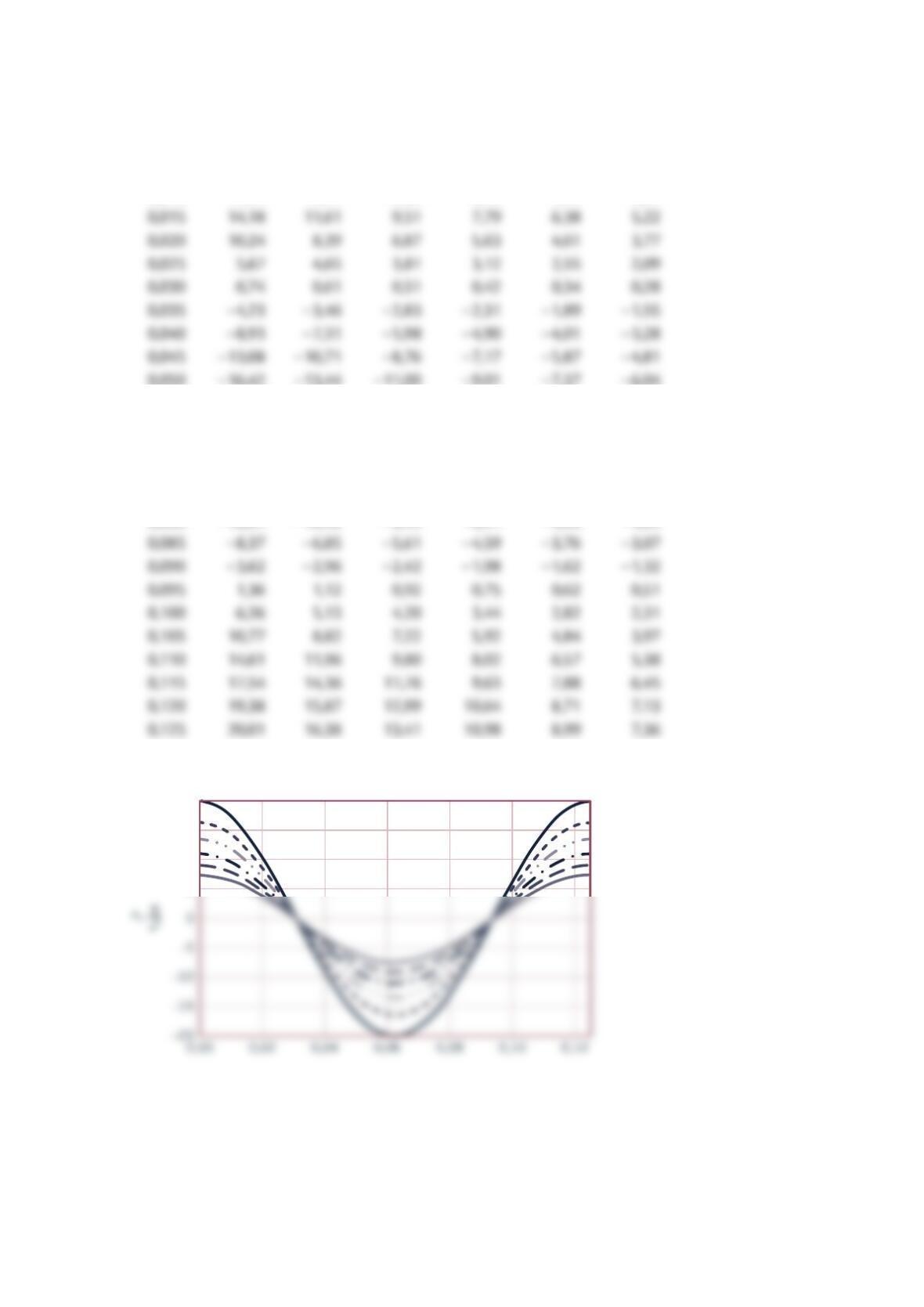
Acceleration at various x locations (ft/s2)
t/s x = 0 ft x = 1 ft x = 2 ft x = 3 ft x = 4 ft x = 5 ft
0,000 20,00 16,37 13,41 10,98 8,99 7,36
0,005 19,22 15,73 12,88 10,55 8,64 7,07
0,010 17,24 14,11 11,56 9,46 7,75 6,34
0,050 −16,42 −13,44 −11,00 −9,01 −7,37 −6,04
0,055 −18,73 −15,34 −12,56 −10,28 −8,42 −6,89
0,060 −19,89 −16,29 −13,33 −10,92 −8,94 −7,32
0,065 −19,81 −16,22 −13,28 −10,87 −8,90 −7,29
0,070 −18,51 −15,15 −12,41 −10,16 −8,32 −6,81
0,075 −16,06 −13,14 −10,76 −8,81 −7,21 −5,90
0,080 −12,61 −10,32 −8,45 −6,91 −5,66 −4,63
10
5
15
20
3
5
4
1
2
0
x, ft
Acceleration, a
x
, vs Time, t
Problem 4.43
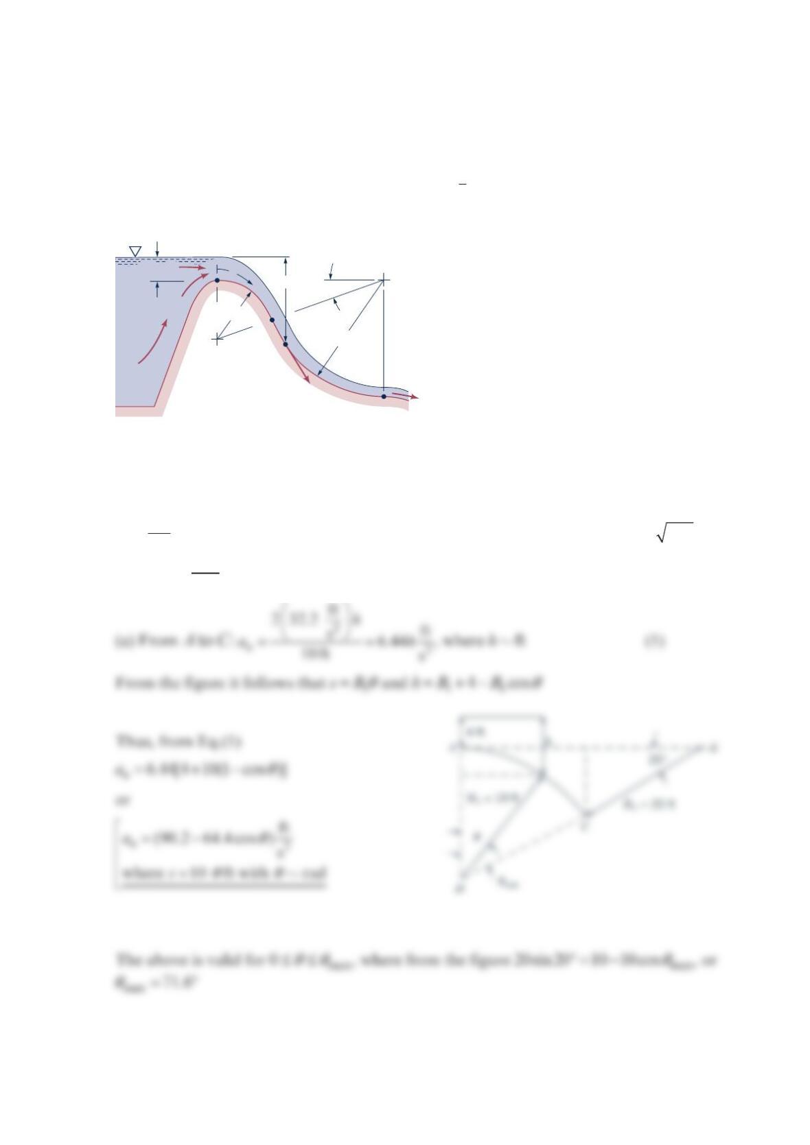
Water flows down the face of the dam as shown in the figure below. The face of the dam
consists of two circular arcs with radii of
1
0 and
2
0f
t
as shown. If the speed of the water
along streamline −
A
B is approximately =
1
2
(2 )
V
gh , where the distance h is as indicated,
plot the normal acceleration as a function of distance along the streamline, =()
nn
a
as
.
Solution 4.43
=
2
n
V
a
R where ==
110 ft
R
R from to
AC
, ==
220 ft
R
R from to C
B
, and =2
V
gh.
Thus, =2
n
gh
a
R
4 ft
s
Ah
C
V
B
20°
ℛ
2 = 20 ft
ℛ
1 = 10 ft
AC
s
h
(b) From to C
B
:
==
2
2
ft
232.2 ft
s3.22
20 ft s
n
h
a
h, where ft
h
(2)
From the figure, it follows that
β
=+°+
2sin( 20 ) 4
h
R and
β
=+
2c
s
sR
where from part (a)
For example, if
β
=0 (i.e., point
C
), =2
ft
34.9 s
n
a
and =12.5ft
s
Note that this value does not agree with =2
ft
69.8 s
n
a
at point
C
calculated in part (a). There
is a discontinuity in n
a
at point
C
because there is discontinuity in the radius of curvature
from =
110 ft
R
to =
220ft
R
. At point B,
β
=°70.0 so that =2
ft
77.3 s
n
a
and =36.9ft
s
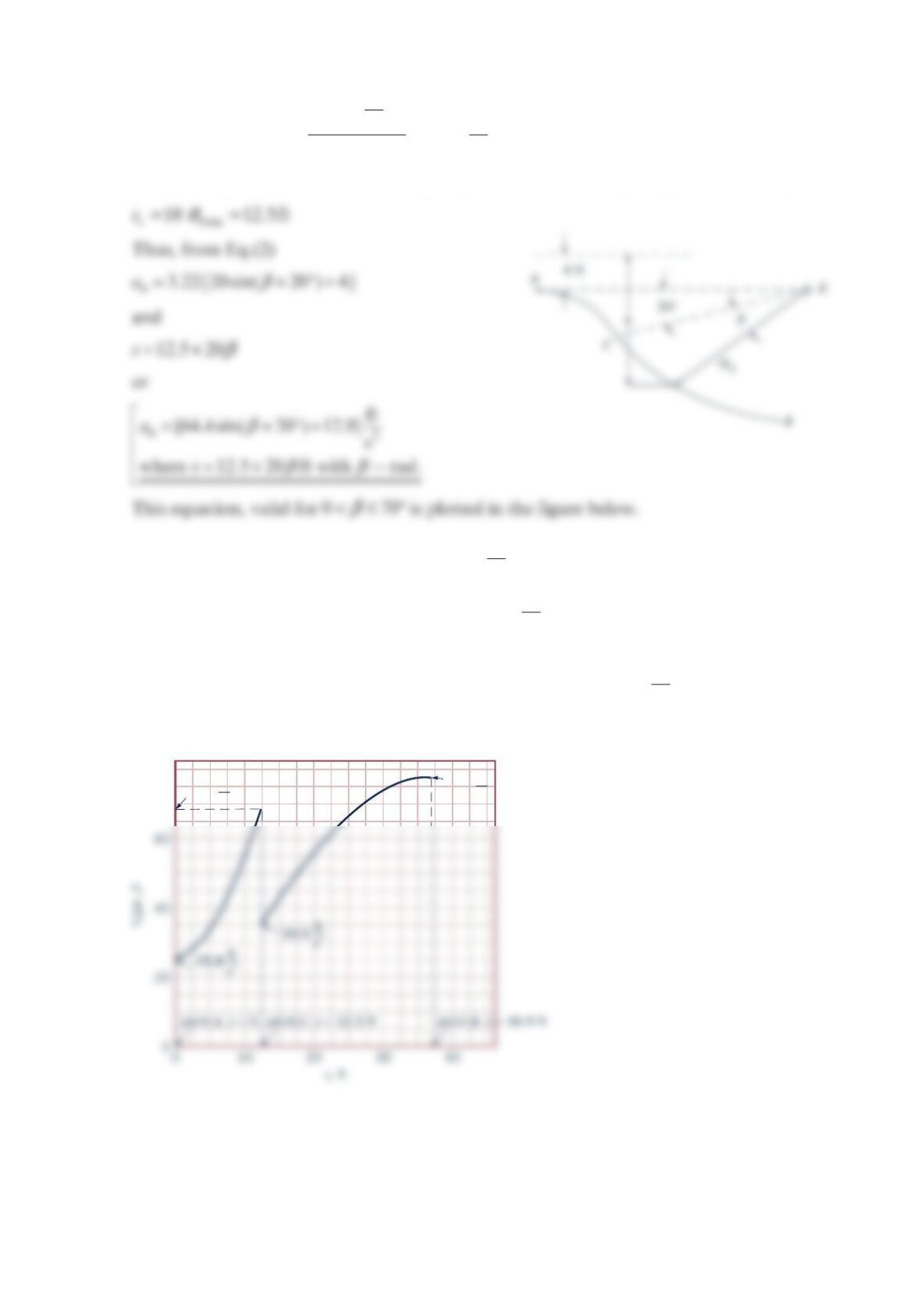
The normal acceleration is plotted as a function of distance along the surface.
ft
s2
69.8
ft
s2
77.3
80
s
β
s
β
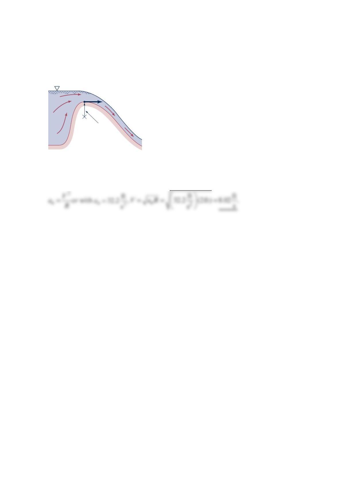
Problem 4.44
Water flows over the crest of a dam with speed
V
as shown in the figure below. Determine
the speed if the magnitude of the normal acceleration at point (1) is to equal the
acceleration of gravity, g.
Solution 4.44
ℛ
= 2 ft
V
(1)
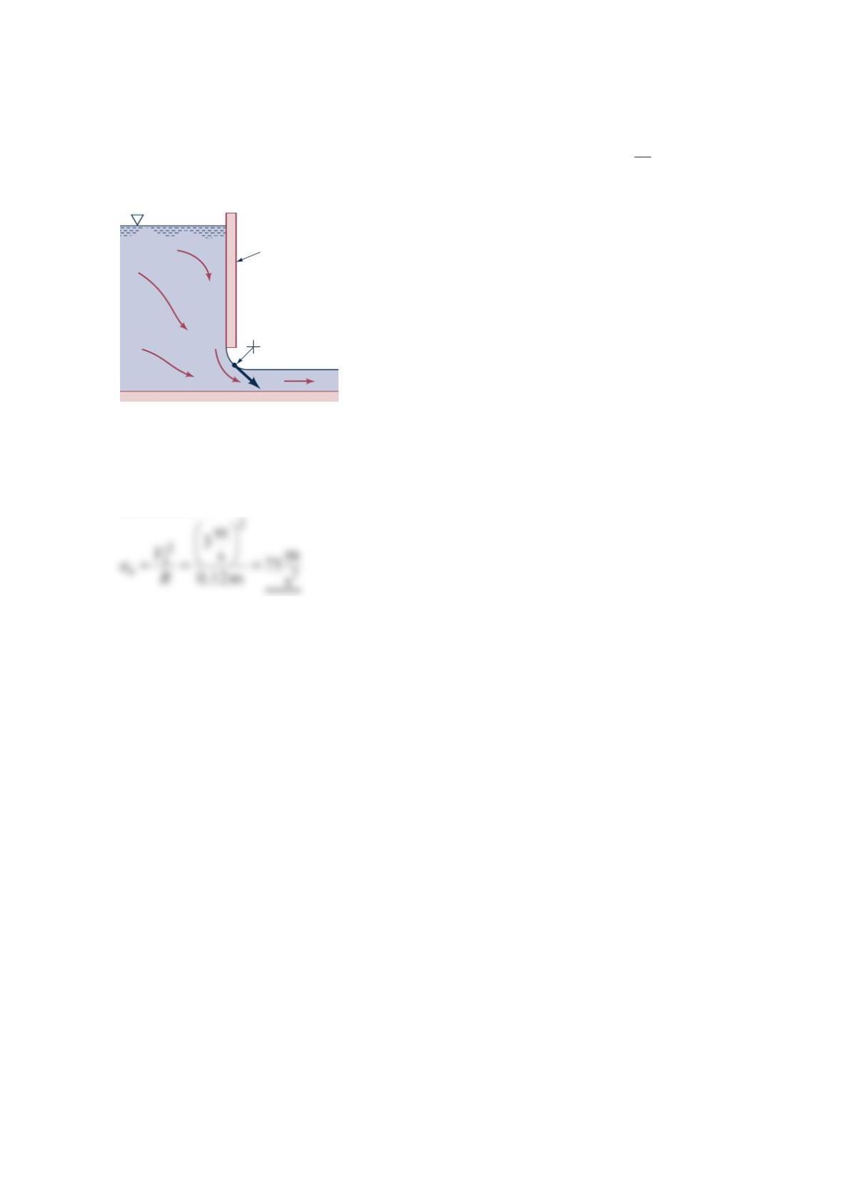
Problem 4.45
Water flows under the sluice gate as shown in the figure below. If =
1
m
3s
V
, what is the
normal acceleration at point (1)?
Solution 4.45
Sluice gate
V
1
= 3 m/s
(1)
ℛ
= 0.12 m
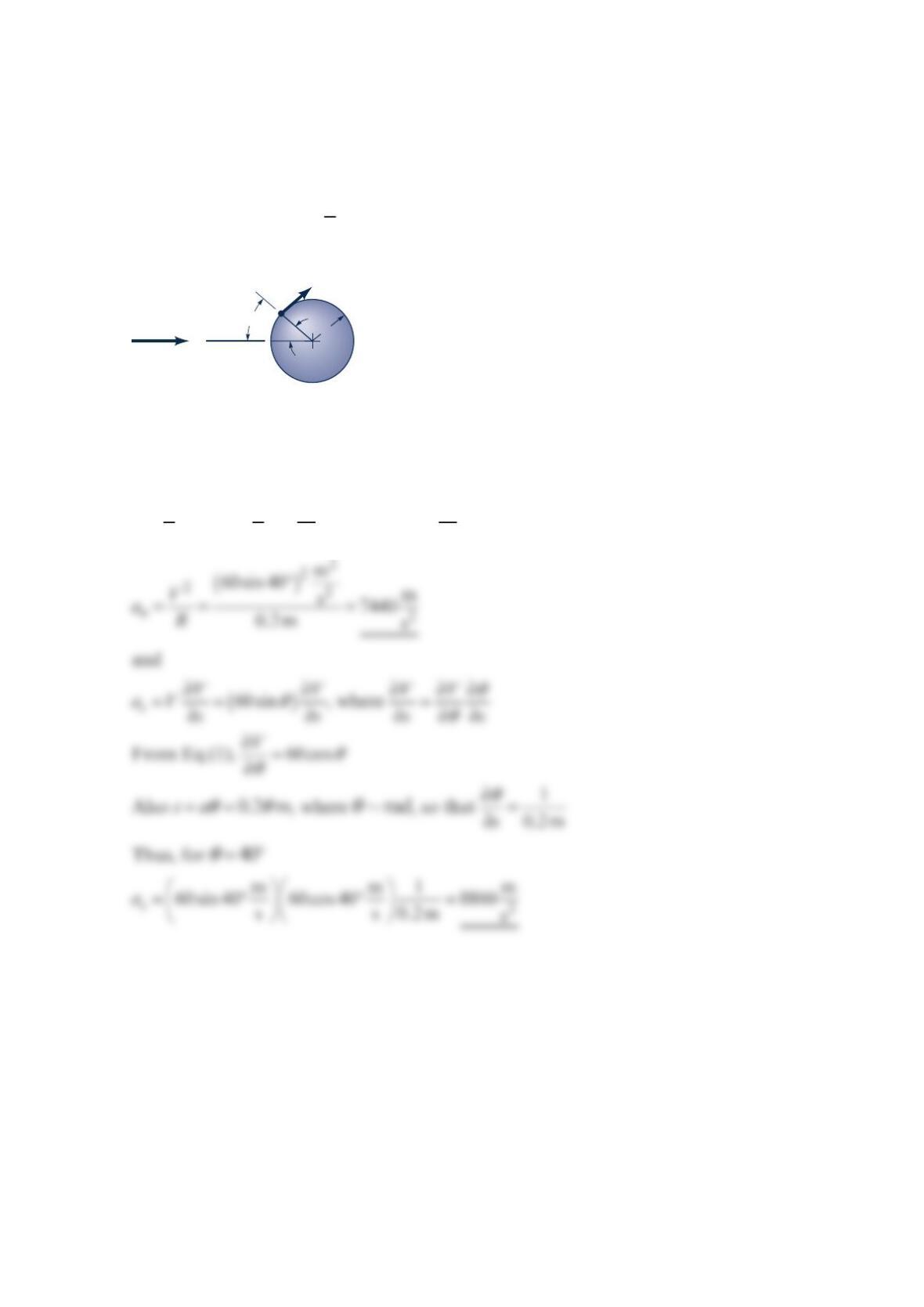
Problem 4.46
A fluid flows past a sphere with an upstream velocity of =
040 m/sV as shown in the figure
below. From a more advanced theory, it is found that the speed of the fluid along the front
part of the sphere is
θ
=0
3sin
2
V
V. Determine the streamwise and normal components of
acceleration at point
A
if the radius of the sphere is =0.20 m
a
.
Solution 4.46
θθθ
== =
0
33m m
sin 40 sin 60sin
22s s
V
V (1)
V
A
a
θ
40°
V0
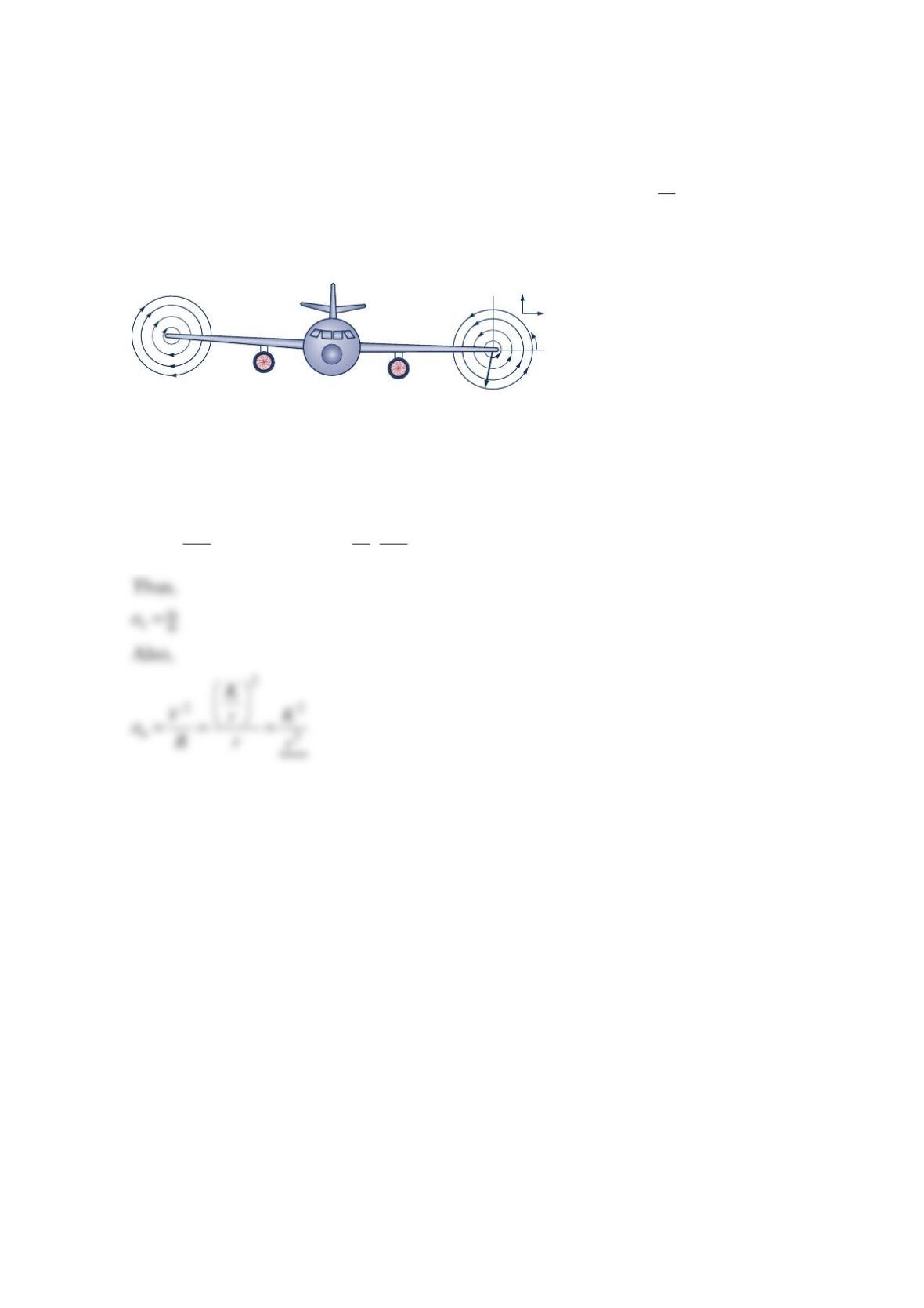
Problem 4.47
Assume that the streamlines for the wingtip vortices from an airplane (see the figure below)
can be approximated by circles of radius
r
and that the speed is =K
Vr, where
K
is a
constant. Determine the streamline acceleration,
s
a
, and the normal acceleration, n
a
, for this
flow.
Solution 4.47
=
s
dV
a
Vds , where, since =K
Vr, =0
dV
ds
S
x
u
ℛ
=
r
v
y