With T
dh
Vdt
=,
Thus,
Hence,
Thus,
()
0
88.7
2
Ldh
t
hhLhL
=
++++
where 2ft=0.1667 ft
12
L=
Note: With
L
in feet, this equation gives t in seconds.
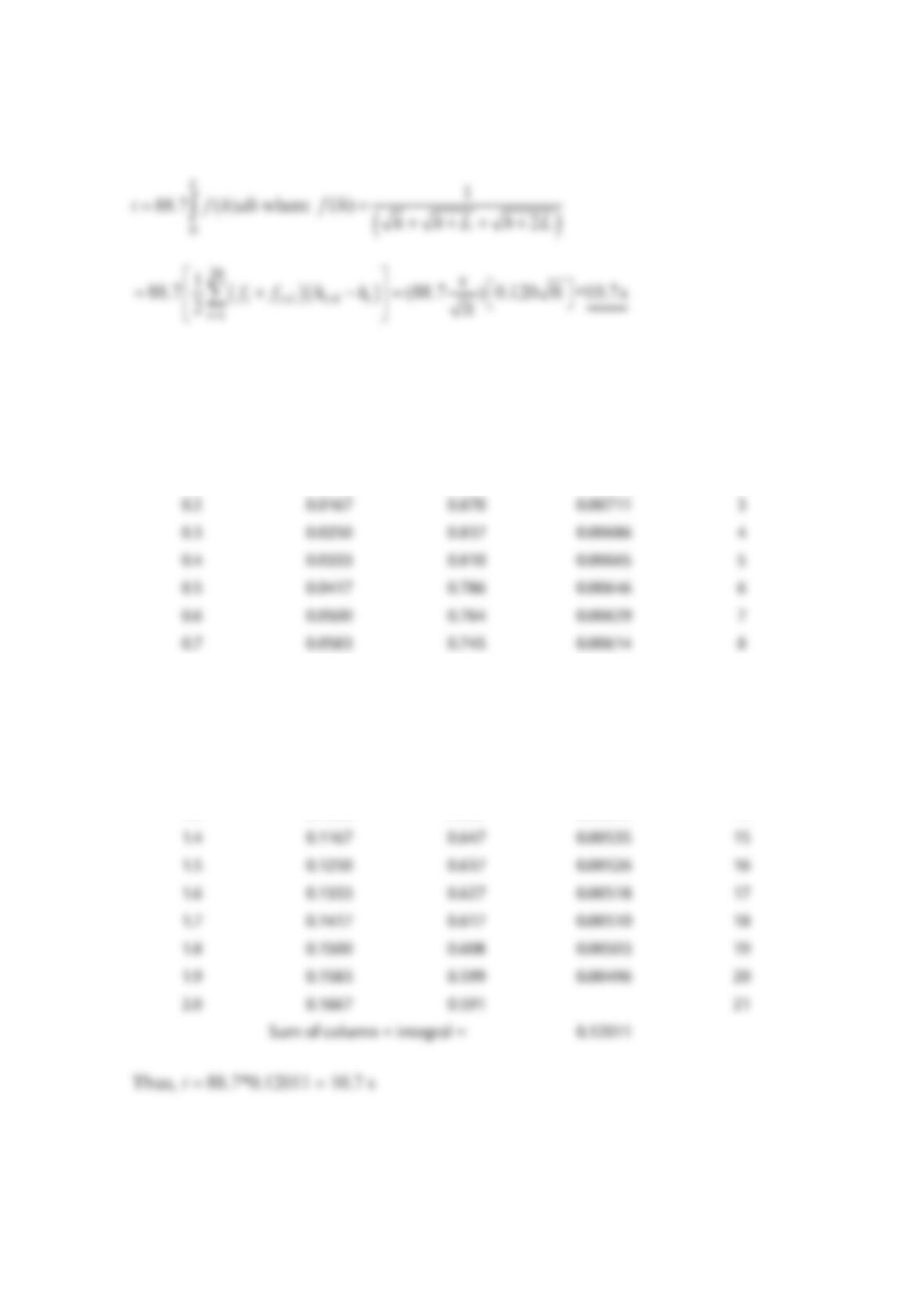
The numerical valve of the integral is obtained by using the trapezoidal rule (or the
1
/3
Simpons Rule) since the closed form analytical solution is not given in integral tables. The
EXCEL spread sheet used for the trapezoidal rule this is given below.
h, (in.) h, (ft) f(h), (1/ft)1/2 (1/2)*(fi + fi+1)*
(hi+1 − hi), (ft1/2)
i
0.0 0.0000 1.015 0.00804 1
0.1 0.0083 0.914 0.00743 2
0.8 0.0667 0.728 0.00600 9
0.9 0.0750 0.712 0.00587 10
1.0 0.0833 0.697 0.00575 11
1.1 0.0917 0.684 0.00564 12
1.2 0.1000 0.671 0.00554 13
1.3 0.1083 0.659 0.00544 14
Problem 3.104
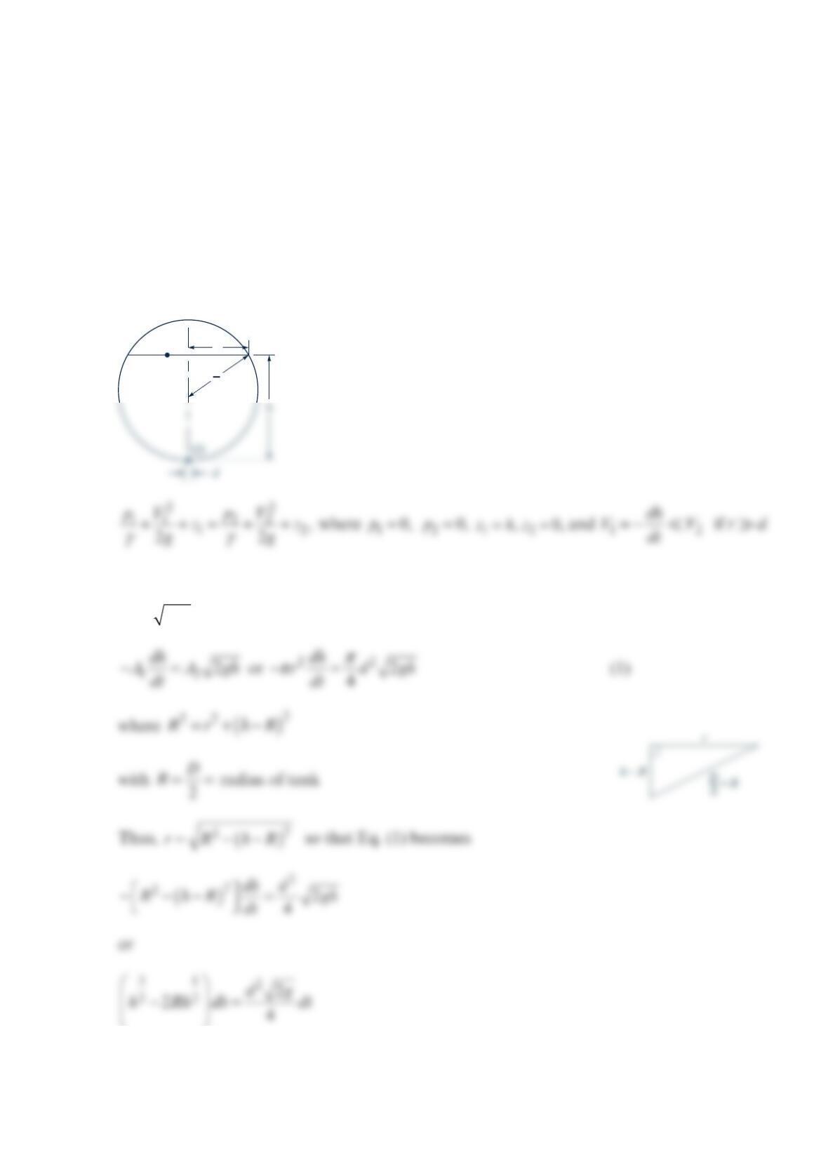
A spherical tank of diameter
D
has a drain hole of diameter d at its bottom. A vent at the
top of the tank maintains atmospheric pressure at the liquid surface within the tank. The
flow is quasi-steady and inviscid and the tank is full of water initially. Determine the water
depth as a function of time, ()
h
ht=, and plot graphs of (
)
h
t for tank diameters of
1
,5,10
,
and
2
0f
t
if 1in.d=
Solution 3.104
Thus,
22Vgh=which when combined with 11 2 2
AV A V= gives
2
D
r
(1)
which can be integrated from the initial time and depth (0, 2)thR== to an arbitrary time
and depth
(
,
)
th as
or
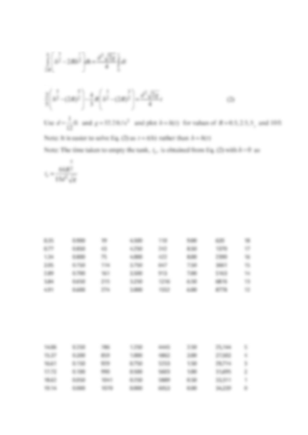
Results of an EXCEL Program to calculate h(t) from Eq. (2):
D = 1 ft D = 5 ft D = 10 ft D = 20 ft
t, s h, ft t, s h, ft t, s h, ft t, s h, ft
0.00 1.000 0 5.000 0 10.00 0 20
0.09 0.950 5 4.750 28 9.50 158 19
6.06 0.550 339 2.750 1917 5.50 10,846 11
7.30 0.500 408 2.500 2308 5.00 13,055 10
8.60 0.450 481 2.250 2718 4.50 15,376 9
9.94 0.400 556 2.000 3143 4.00 17,782 8
11.31 0.350 632 1.750 3577 3.50 20,237 7
12.69 0.300 710 1.500 4014 3.00 22,706 6
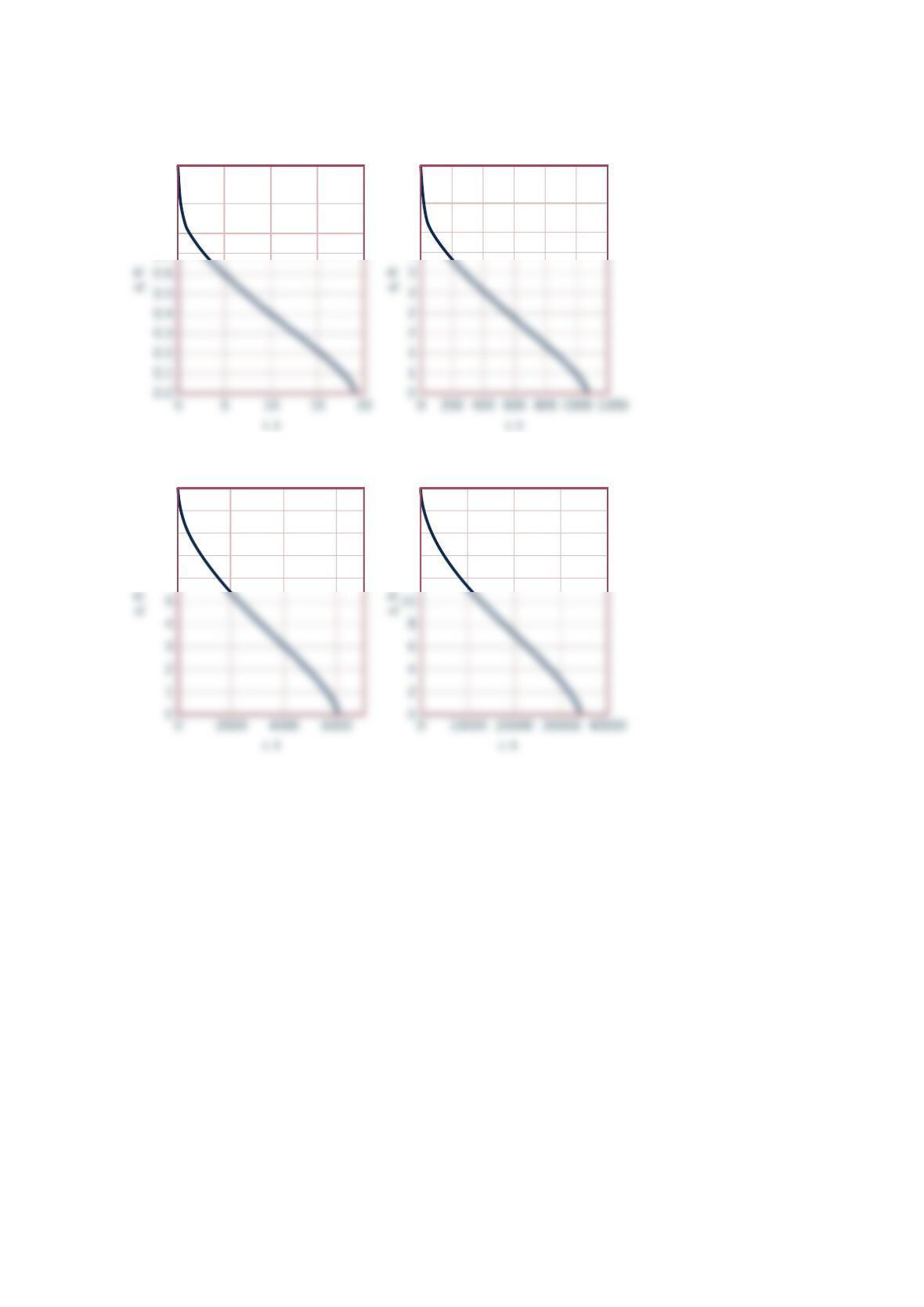
Below are the graphs of above results.
1.0
Water Depth vs Time
D
= 1 ft
Water Depth vs Time
D
= 5 ft
0.9
0.8
0.7
5
5
4
4
10
Water Depth vs Time
D
= 10 ft
9
8
7
6
20
Water Depth vs Time
D
= 20 ft
18
16
14
12
Problem 3.106
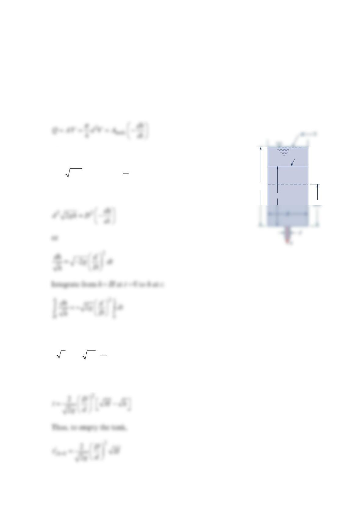
When the drain plug is pulled, water flows from a hole in the bottom of a large, open cylin-
drical tank. Show that if viscous effects are negligible and if the flow is assumed to be qua-
sisteady, then it takes
3
.4
1
times longer to empty the entire tank than it does to empty the
first half of the tank. Explain why this is so.
Solution 3.106
where
2Vgh= and 2
tank 4
AD
π
=
Thus,
or
2
22
h
H
d
hgt
D
=−
or
h
H
at
t
and to half empty the tank,
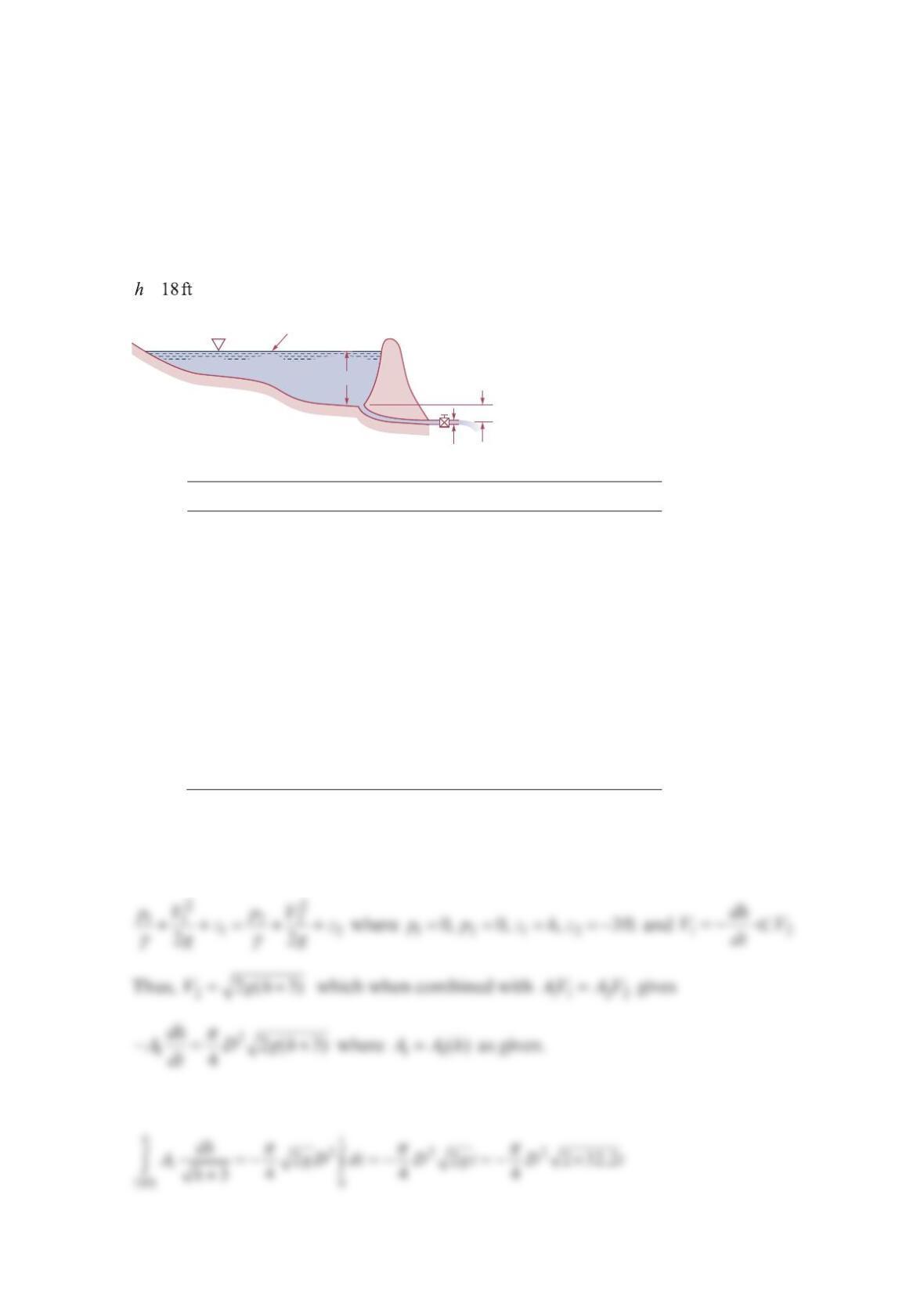
Problem 3.107
Someone siphoned 15 gal of gasoline from a gas tank in the middle of the night. The gas
tank measures 12 in. wide × 24 in. long × 18 in. high and was full when the thief started. If
the siphoning tube has an inside diameter of 1in.
2, find the minimum amount of time need-
ed to siphon the 15 gal from the tank. Assume that at any instant of time the steady-state
equations are adequate to predict the gasoline velocity in the siphon tube. Also assume that
the end of the siphon tube outside the gas tank is at the same level as the bottom of the
tank. You may consider the gasoline to be inviscid.
Solution 3.107
The minimum time is for inviscid flow. Apply Bernoulli’s equation from gasoline free sur-
face (1) to siphon tube outlet (2). Note 12 atm
p
pp== and 00V≈.
This gives
where 018 in.h= Integrating gives
Since
2
24
d
A
π
= with 1in.
2
d=,
Now,
or
The numerical values give
Problem 3.108
The surface area,
A
, of the pond shown in the figure below varies with the water depth, h, as
shown in the table. At time t = 0 a valve is opened and the pond is allowed to drain through
a pipe of diameter
D
. If viscous effects are negligible and quasisteady conditions are
assumed, plot the water depth as a function of time from when the valve is opened (0)t=
until the pond is drained for pipe diameters of 0.5,1.0,1.5, 2.0, 2.5,D=and 3.0 ft . Assume
=at t = 0.
h (ft) A [acres (1 acre = 43,560 ft2)]
0 0
2 0.3
4 0.5
6 0.8
8 0.9
10 1.1
12 1.5
14 1.8
16 2.4
18 2.8
Solution 3.108
This can be rearranged and integrated to give
Area A
h
D
3 ft
or
Note: It is easier to determine t as a function of h rather than h as a function of t
Note: 2
tD
−
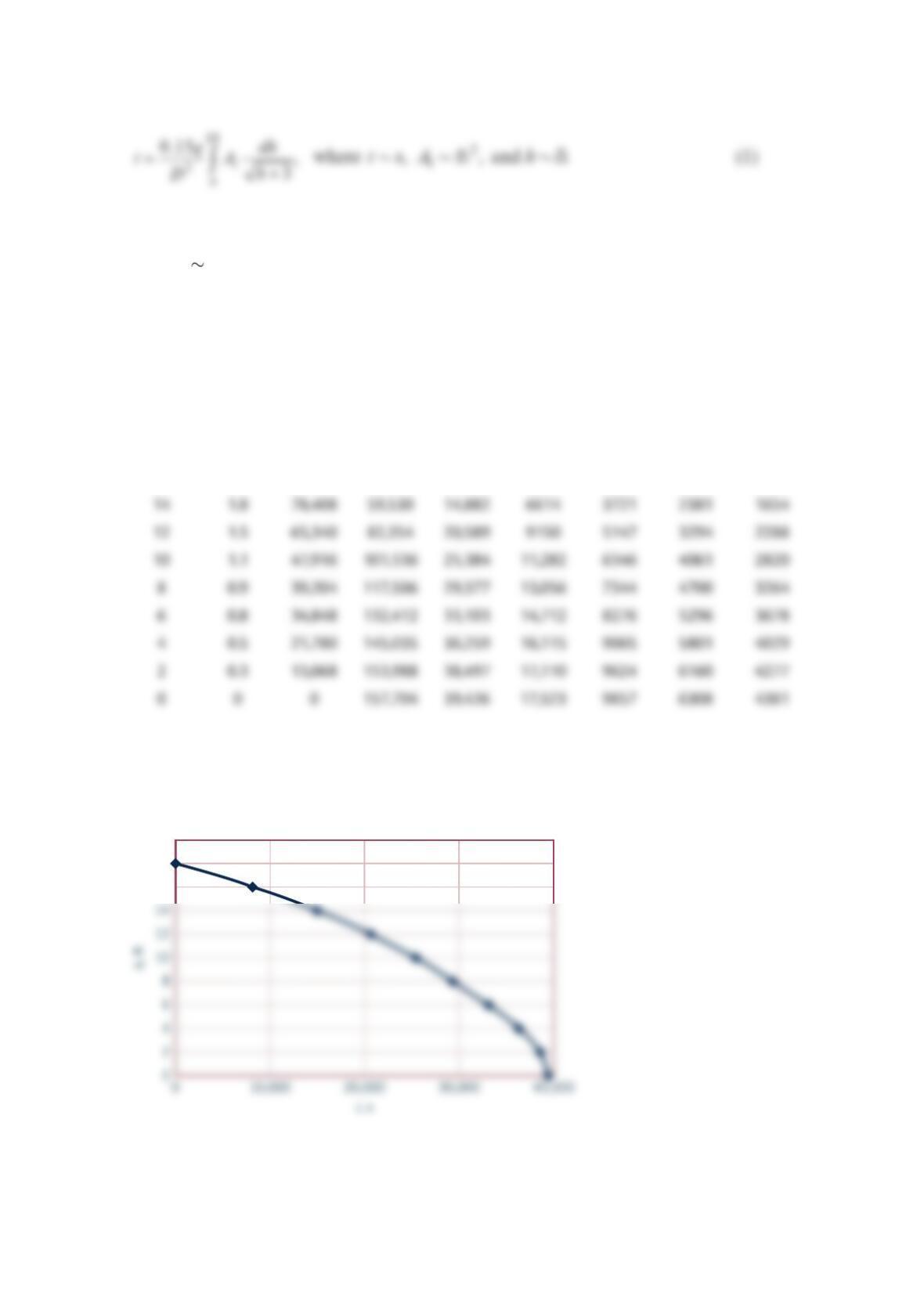
An EXCEL Program using a trapezoidal integration approximation was used to calculate the results
shown below.
D = 0.5
ft
D = 1.0
ft
D = 1.5
ft
D = 2.0
ft
D = 2.5
ft
D = 3.0
ft
h, ft A, acres A, ft2 t, s t, s t, s t, s t, s t, s
18 2.8 121,968 0 0 0 0 0 0
16 2.4 104,544 32,181 8045 3576 2011 1287 894
The graph for D = 1 ft is shown below. The shape of the curve is the same for any D
20
18
16
Water Depth vs Time
for
D
= 1 ft
Problem 3.109
Water flows through a horizontal branching pipe as shown in the figure below. Determine
the pressure at section (3).
Solution 3.109
Thus,
Thus,
V1 = 4 m/s
p1 = 400 kPa
A1 = 0.1 m2
V2
V3
p2 = 350 kPa
A3 = 0.07 m2
A2 = 0.02 m2
(2)
(3)
(1)
we obtain
or
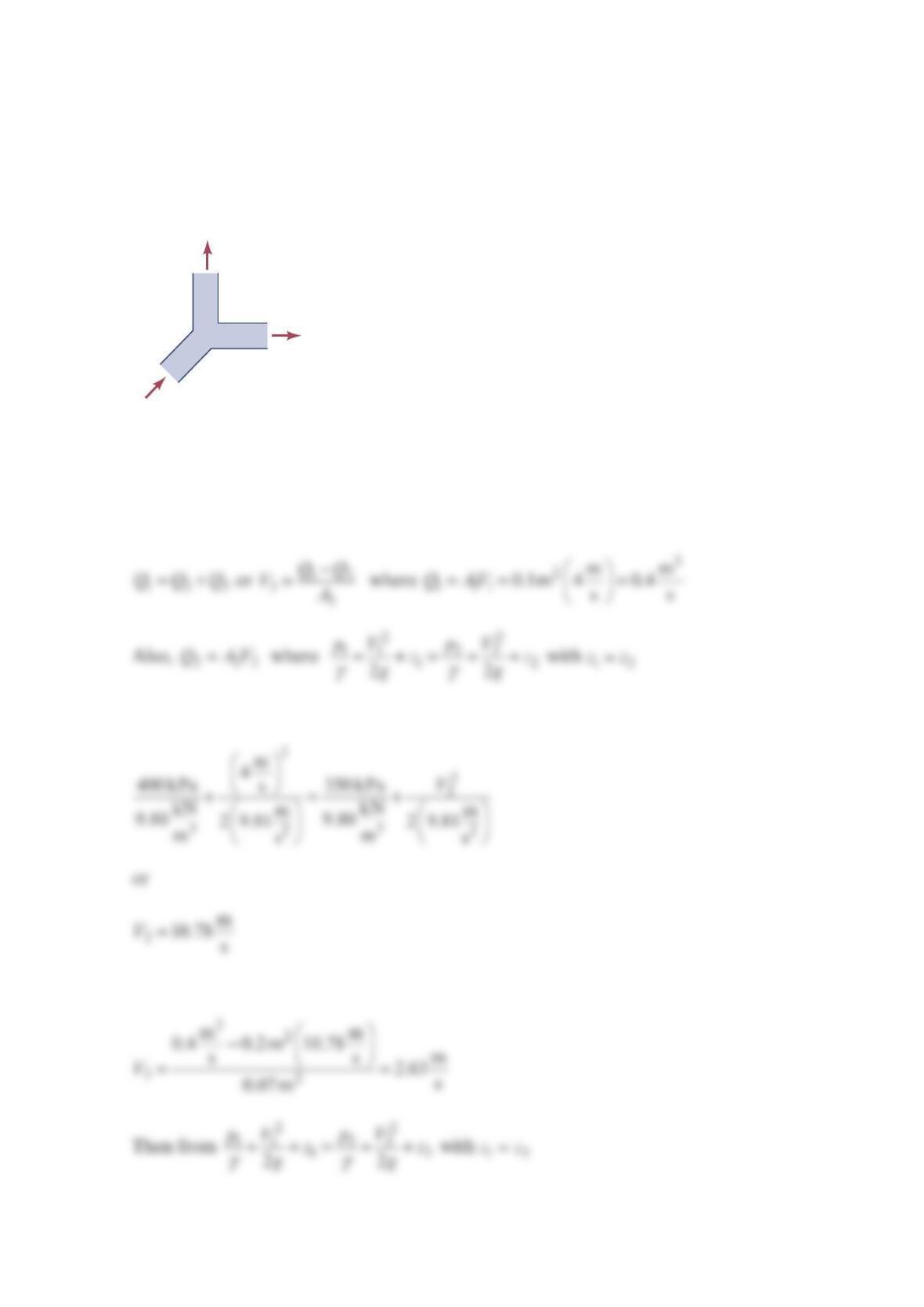
Problem 3.110
The “wye” fitting shown in the figure below lies in a horizontal plane. The fitting splits the
inlet flow into two equal parts. At section
1
, the water velocity is 12 ft / sec and the pressure
is 20 psig . Calculate the water pressure at sections
2
and
3
. Assume inviscid flow and a
water temperature of 60°F.
Solution 3.110
Apply Bernoulli’s equation to a streamline between points
1
and
2
. Assume no elevation
changes and constant water density.
In a similar manner, apply Bernoulli’s equation between points
1
and
3
to get
The numerical values give
D
2
= 3 in.
D
1
= 6 in.
D
3
= 4 in.
1
D
1
Q
1
D
2
D
3
p
2
p
3
½
Q
1
½
Q
1
2
3
3
244
2
2
22
lbm ft
862.4 2.36s
ft 11
20 psig
ft lbm in. 36
32.2 144 4ft ft
12 12
lb s ft
p
π
=− −
⋅
⋅
and
Problem 3.111
Water flows through the branching pipe shown in the figure below. If viscous effects are
negligible, determine the pressure at section (2
)
and the pressure at section(3).
Solution 3.111
Along the streamline from (1) to (2):
Thus,
or
A
1
= 0.1 m
2
Q
1
= 1 m
3
/s
p
1
= 300 kPa
z
1
= 0
A
3
= 0.035 m
2
A
2
= 0.03 m
2
z
3
= 10 m
z
2
= 0
V
2
= 14 m/s
(1) (2)
(3)
Thus, Eq. (1) becomes (with 13
0, z 10 mz==)
Problem 3.112
Water flows through the horizontal branching pipe shown in the figure below at a rate of
. If viscous effects are negligible, determine the water speed at section (2
)
, the pressure
at section (3), and the flowrate at section (4).
Solution 3.112
Thus, with g=
γρ
22
2
22 22
2
2
lb in. lb in.
ft
10 144 5 144
10
in. ft in. ft
s
V
A
1
= 1 ft
2
Q
1
= 10 ft
3
/s
p
1
= 10 psi
A
2
= 0.07 ft
2
p
2
= 5.0 psi
(2)
A
3
= 0.2 ft
2
V
3
= 20 ft /s
(4)
(3)
(1)
or
32
lb
1150 7.98psi
ft
p==
Also,
Problem 3.113
Water flows from a large tank through a large pipe that splits into two smaller pipes as
shown in the figure below. If viscous effects are negligible, determine the flowrate from the
tank and the pressure at point
(
1).
Solution 3.113
7 m
3 m
0.05-m diameter
0.03-m diameter
0.02-m diameter
(1)
7 m
3 m
(0)