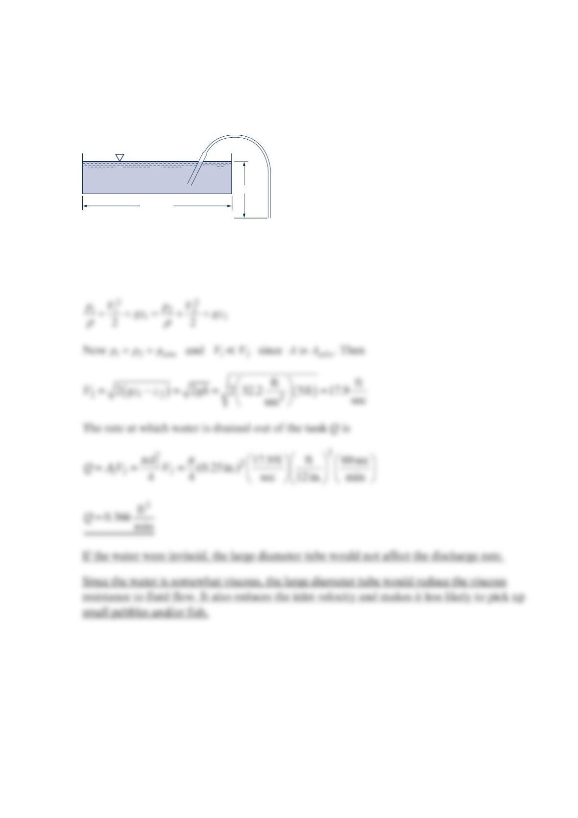
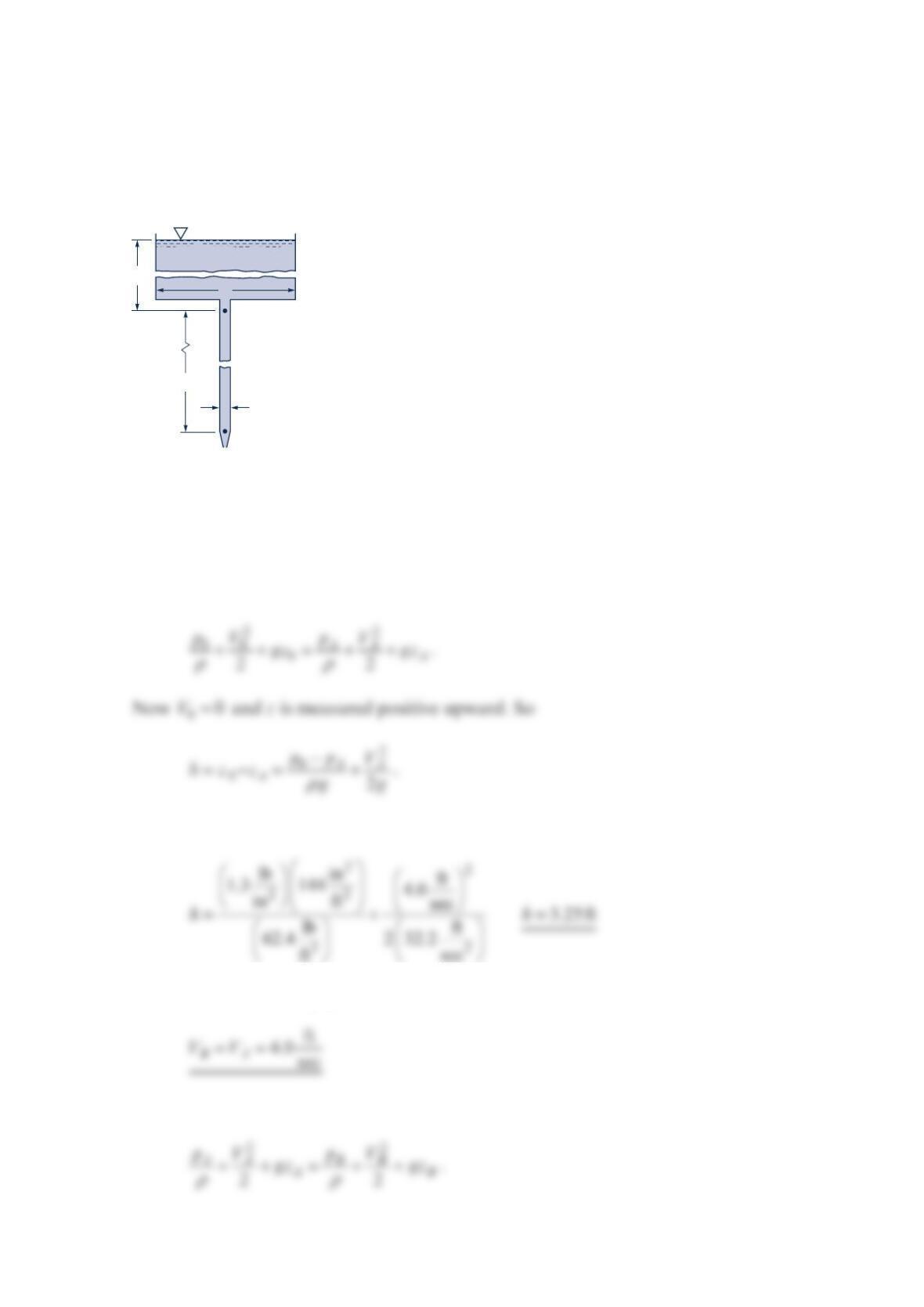
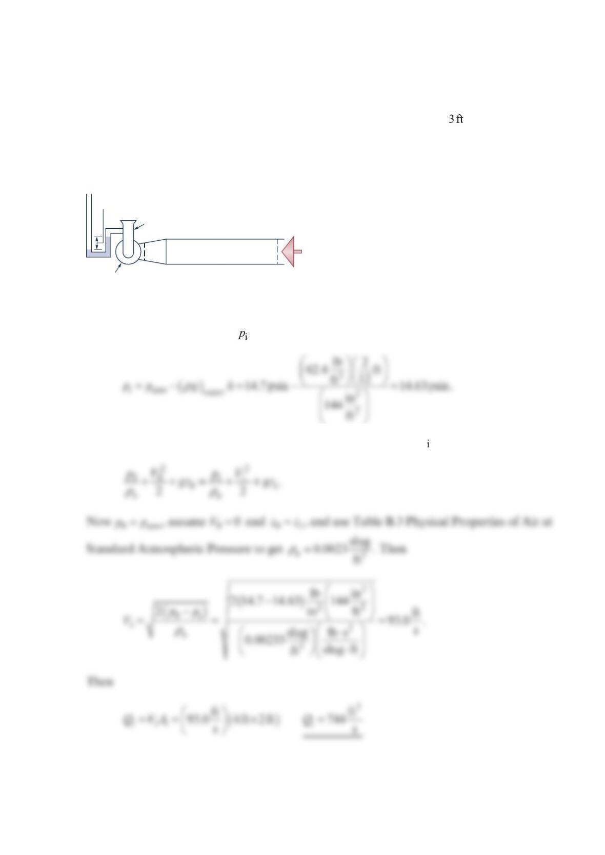
Problem 3.42
The figure below shows a tube for siphoning water from an aquarium. Determine the rate
at which the water leaves the aquarium for the conditions shown. Is there an advantage to
having the large-diameter section? The water flow is inviscid.
Solution 3.42
Denote the aquarium free surface by 1 and the tube outlet by 2. Assuming constant fluid
density, Bernoulli’s equation between point 1 and point 2 gives
¼ in. I.D. tube
A
= 6 ft
2
h
= 5 ft
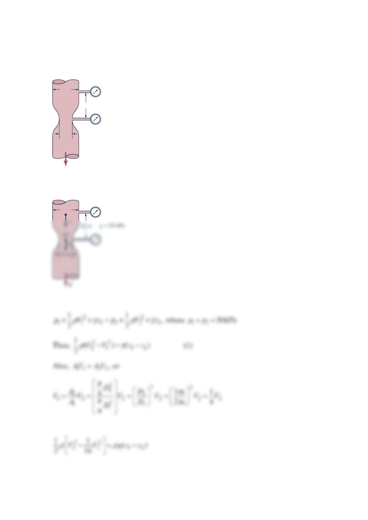
Problem 3.43
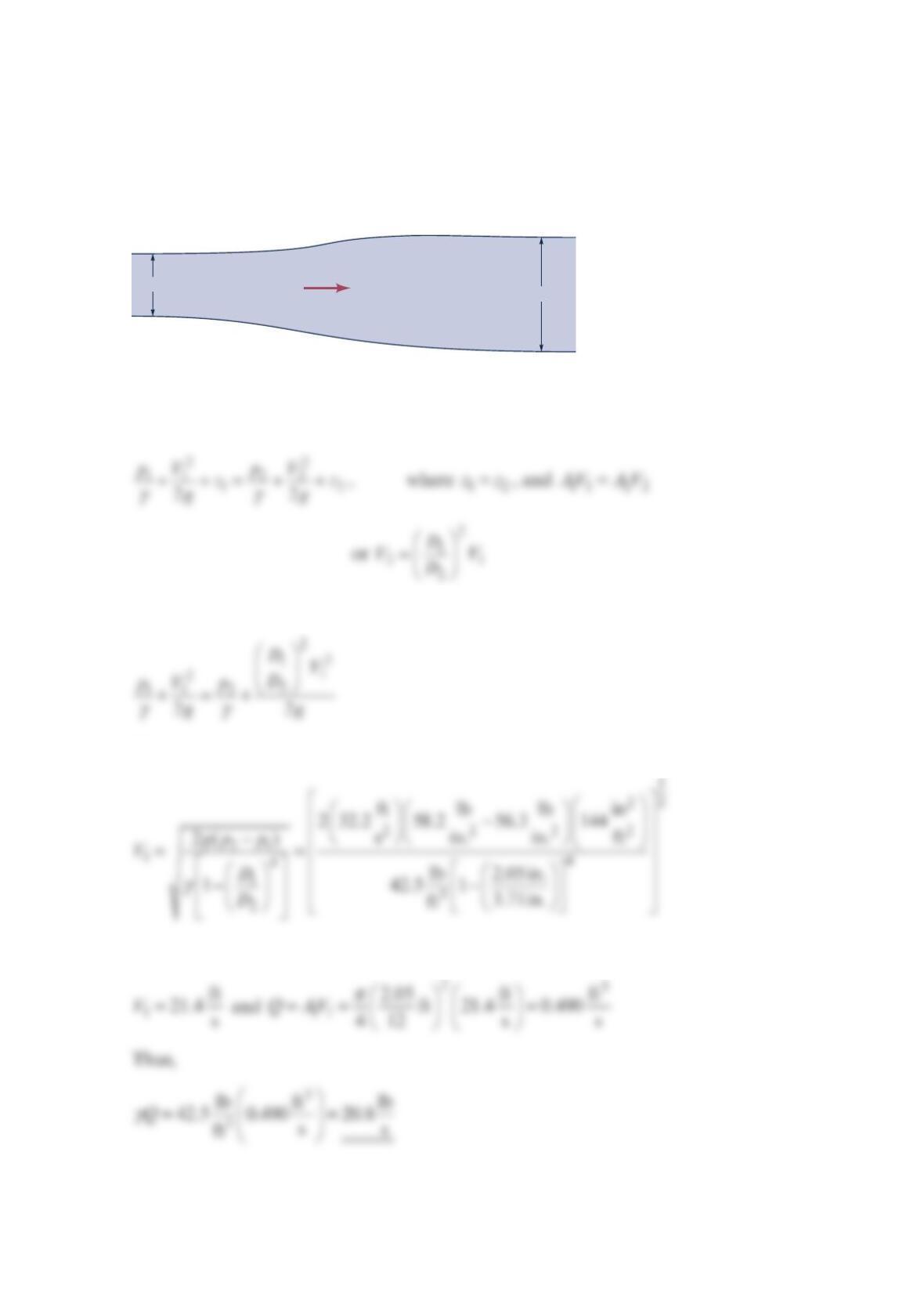
For the pipe enlargement shown in the figure below, the pressures at sections (1) and (2) are
56.3 and psi58.2 , respectively. Determine the weight flowrate (lb/s) of the gasoline in the
pipe.
Solution 3.43
Thus,
or
or
2.05 in. 3.71 in.
Q
(1)
(2)
Gasoline
Problem 3.44
A fire hose nozzle has a diameter of 1
1in.
8 According to some fire codes, the nozzle must be
capable of delivering at least 250 gal/min. If the nozzle is attached to a 3-in. -diameter hose,
what pressure must be maintained just upstream of the nozzle to deliver this flowrate?
Solution 3.44
Thus,
D1
=
3 in.
D2
=
1.125 in.
Problem 3.45
Water flowing from the 0.75-in. -diameter outlet shown in the figure below rises 2.8in.
above the outlet. Determine the flowrate.
Solution 3.45
The flowrate is 11
QAV= where from the Bernoulli’s equation
So that
Q
2.8 in.
0.75 in.
Problem 3.46
A fire hose has a nozzle outlet velocity of 30 mph . What is the maximum height the water
can reach?
Solution 3.46
The maximum height is when the water velocity is directed upward. Apply Bernoulli’s
equation between the nozzle outlet (0) and the maximum height (m). Assume inviscid flow.
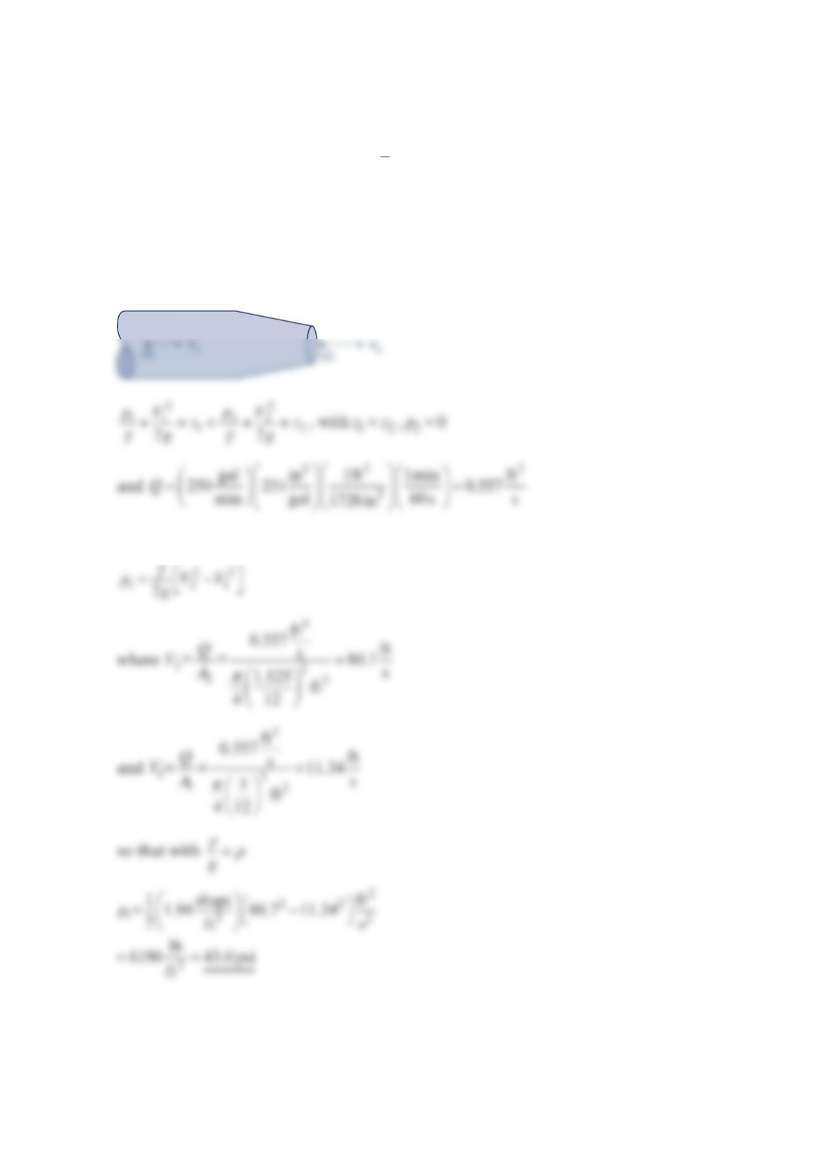
Problem 3.47
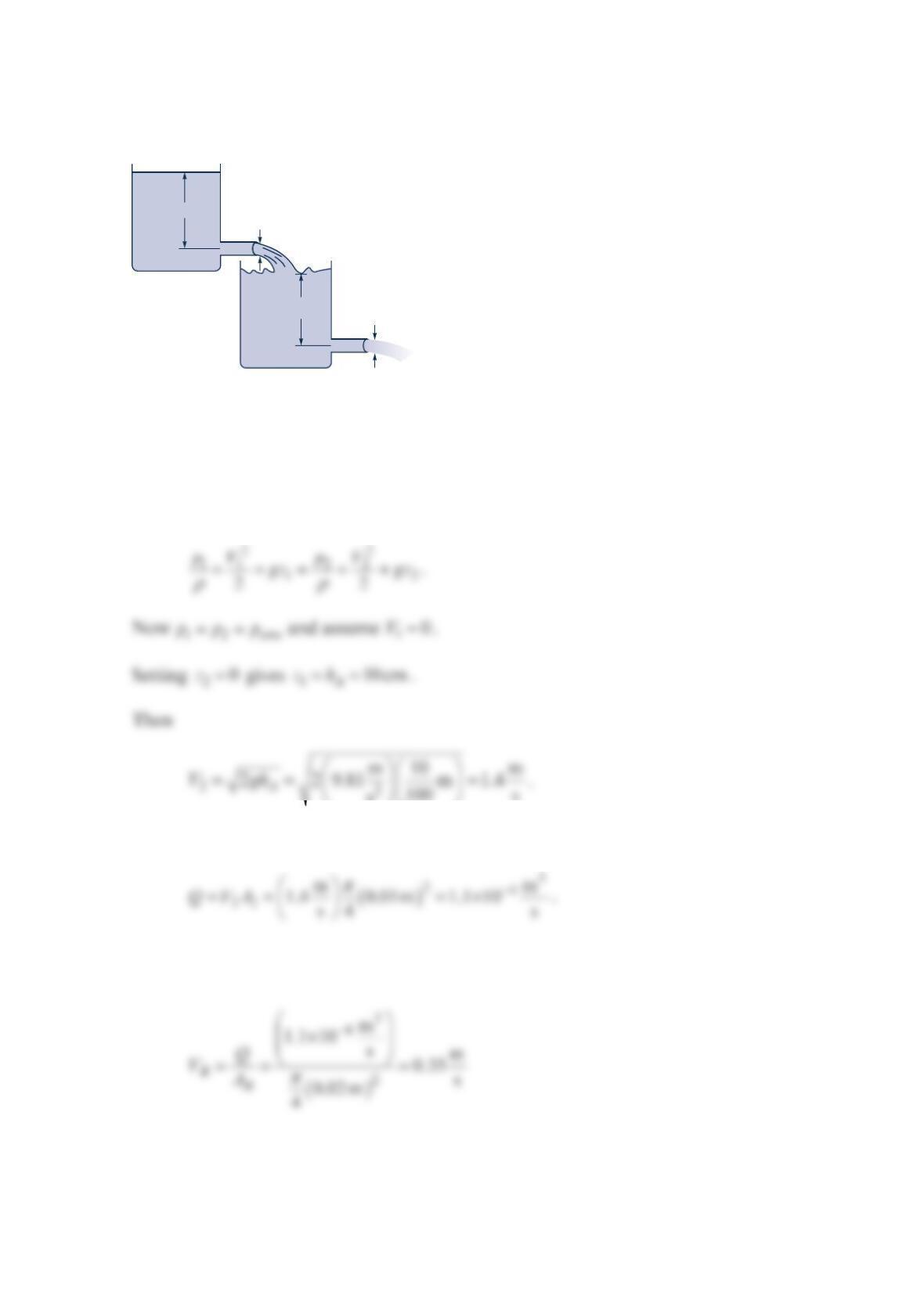
At what rate does oil (SG 0.85) flow from the tank shown in the figure below?
Solution 3.47
Apply Bernoulli’s equation between the oil surface (0) and the outlet (
T
).
Now apply Bernoulli’s equation between the oil surface (0) and the outlet (
B
).
d
T
= 3.0 cm
D
= 14 cm
13.5 cm
Oil
d
B
= 3.0 cm
10.5 cm
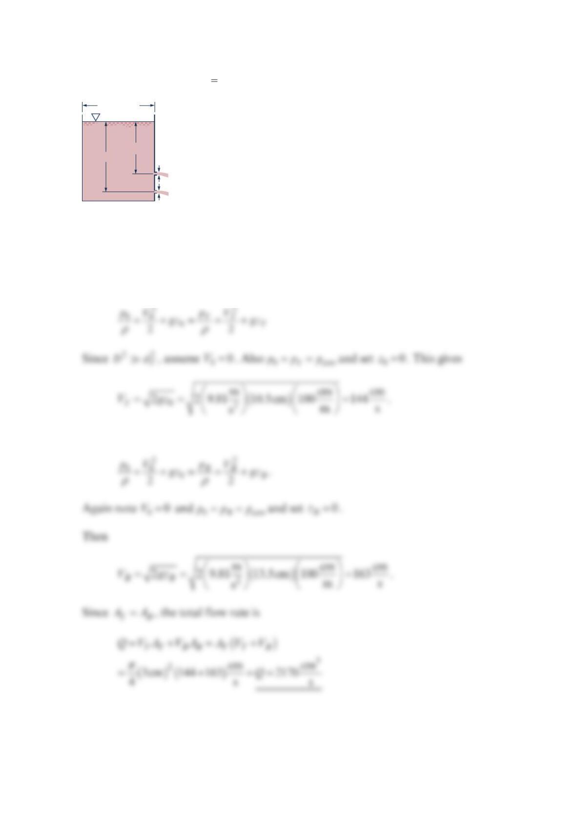
Problem 3.48
Find the water height B
h
in tank
B
shown in the figure below for steady-state conditions.
Solution 3.48
Assume constant fluid density and inviscid flow and apply Bernoulli’s equation to tank
A
from the surface (
1
) to the outlet (
2
).
100 s
s
.
and
From the continuity, the flow rate leaving tank
A
(and entering tank
B
) must equal the rate
leaving tank
B
. So
d
A
= 0.01 m
Tank A
h
A
= 10.0 cm
h
B
Tank B
d
B
= 0.02 m
Now apply Bernoulli’s equation to tank
B
from the surface (3) and the outlet (4).
Then
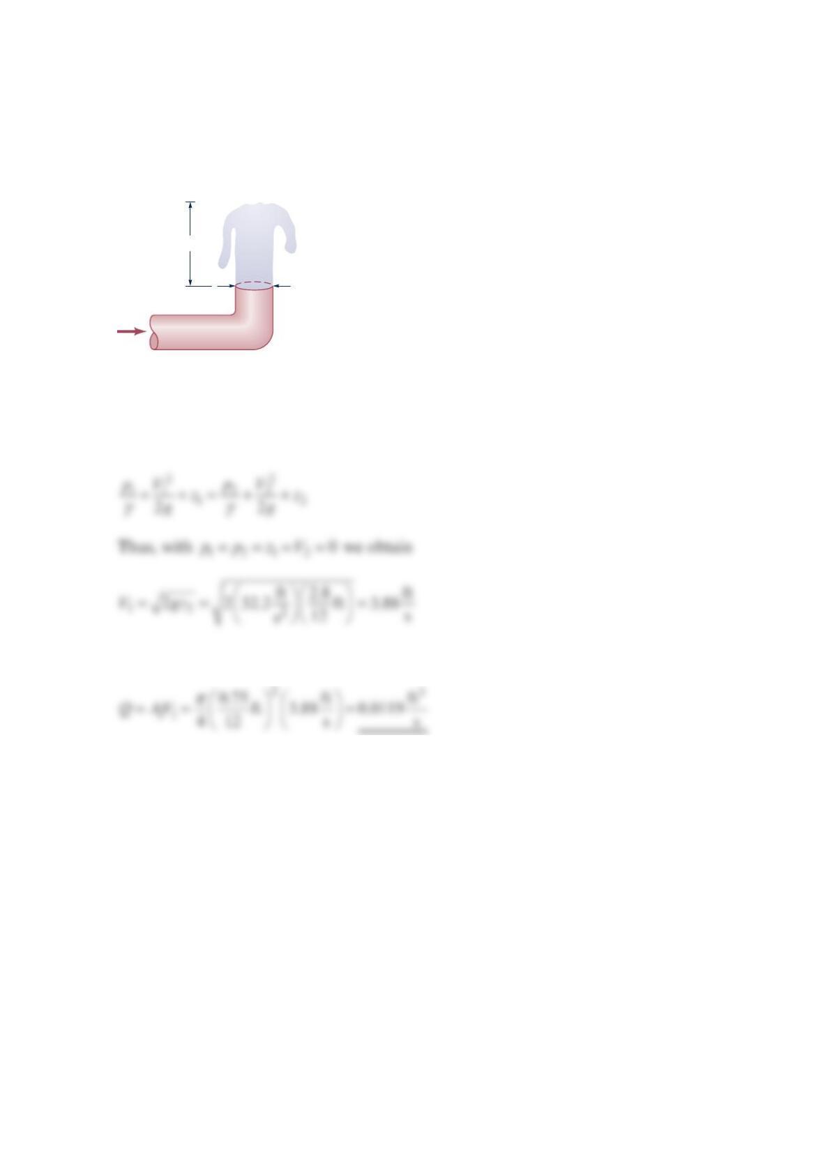
Problem 3.49
The pressure and average velocity at point
A
in the pipe shown in the figure below are
16.0 psia and 4.0 ft / sec , respectively. Find the height h and the pressure and average
velocity at point
B
. Fluid fills the 1-i n. -diameter discharge pipe.
Solution 3.49
Assume incompressible, inviscid flow. Appling Bernoulli’s equation to a streamline from
the free water surface (0) to point
A
gives
The numerical values give
Since the fluid fills the pipe,
Now apply Bernoulli’s equation between points
A
and
B
.
d
= 1 in.-diameter plastic pipe
D
A
B
60 °F water
p
atm
h
5 ft
Since AB
VV=,
Problem 3.50
Water (assumed inviscid and incompressible) flows steadily in the vertical variable-area
pipe shown in the figure below. Determine the flowrate if the pressure in each of the gages
reads 50kPa.
Solution 3.50
From the Bernoulli’s equation,
Hence, Eq. (1) becomes
Q
10 m
1 m
2 m
p
= 50 kPa
2 m
(1)
or
or
Thus,
Problem 3.51
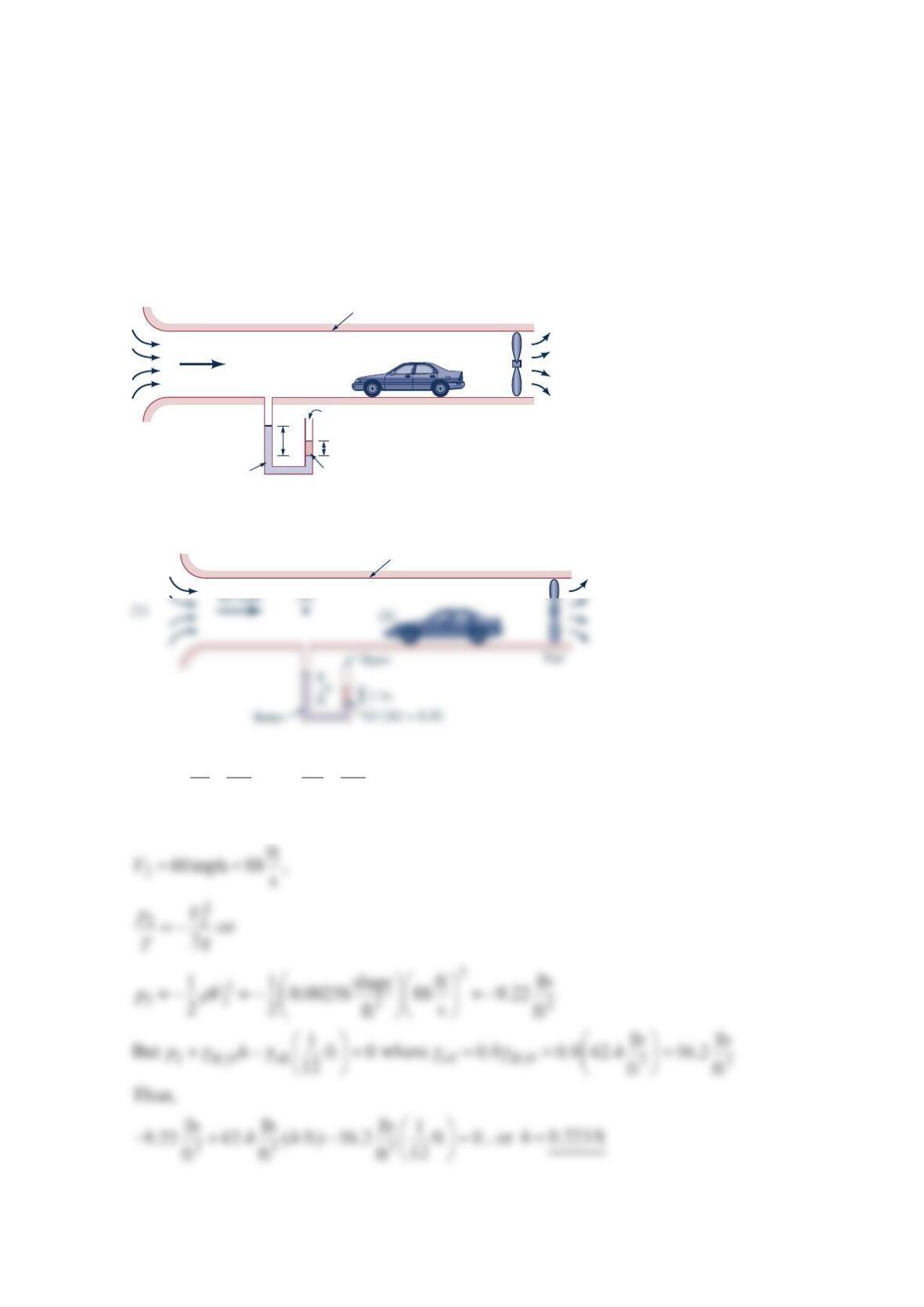
Air is drawn into a wind tunnel used for testing automobiles as shown in the figure below
(a) Determine the manometer reading, h, when the velocity in the test section is mph60 .
Note that there is a 1-in. column of oil on the water in the manometer. (b) Determine the
difference between the stagnation pressure on the front of the automobile and the pressure
in the test section.
Solution 3.51
(a)
22
11 2 2
12
22
pV p V
zz
gg
γγ
++=++, where 12
zz=, 10p=, and 10V≈
Thus, with
Wind tunnel
Fan
60 mph
h
Water
Open
1 in.
Oil (SG = 0.9)
Wind tunnel
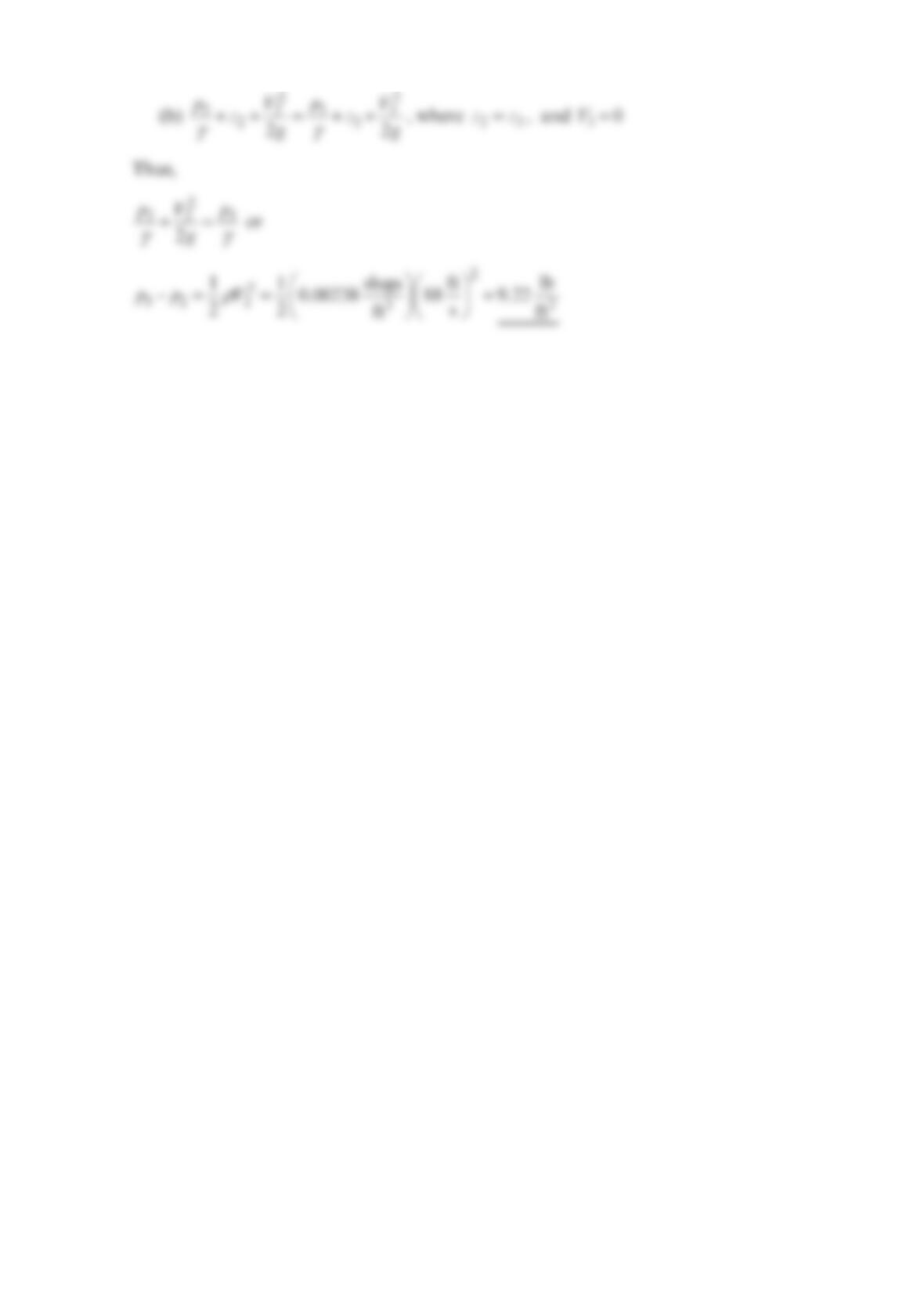
Problem 3.52
The figure below shows a duct for testing a centrifugal fan. Air is drawn from the
atmosphere
(
14.7 psia, 70 F)
atm atm
p
T==°
. The inlet box is 4ft 2ft×. At section
1
, the duct
is 2.5 ft square. At section
2
, the duct is circular and has a diameter of . A water
manometer in the inlet box measures a static pressure of 2.0 in.− of water. Calculate the
volume flow rate of air into the fan and the average fluid velocity at both sections
1
and
2
.
Assume constant density.
Solution 3.52
The pressure in the inlet box is
Now apply Bernoulli’s equation from the atmosphere to the inlet .
Throttling
plug
(2)
(1)
Fan
Inlet box
2 in. water
The continuity equation gives
and
Problem 3.53
Natural gas (methane) flows from a 3-in. -diameter gas main, through a 1-in. -diameter
pipe, and into the burner of a furnace at a rate of
3
ft
1
00 hr . Determine the pressure in the gas
main if the pressure in the 1-in. pipe is to be in
.
6 of water greater than atmospheric
pressure. Neglect viscous effects.
Solution 3.53
Thus,
or
1 in.
3 in.
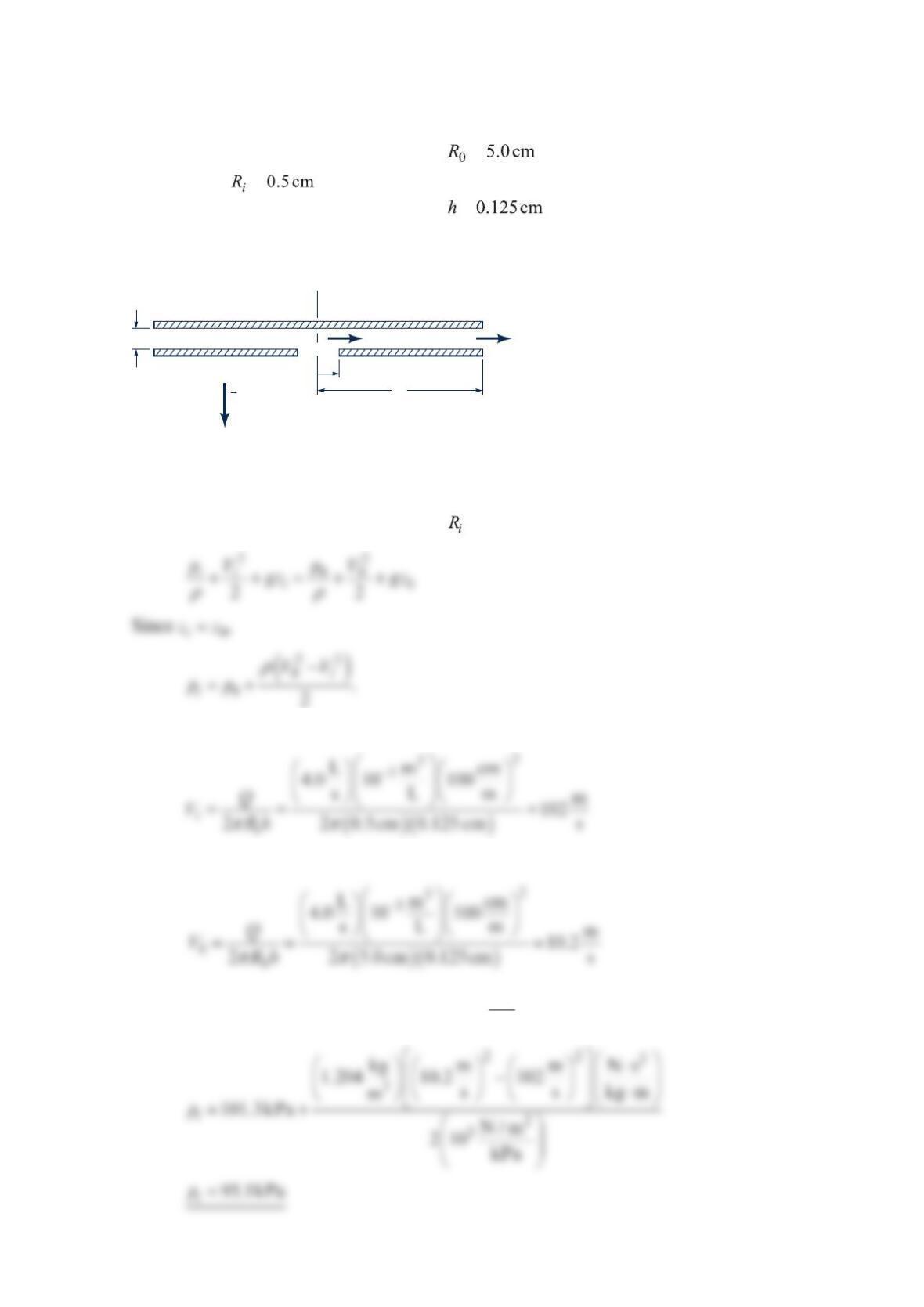
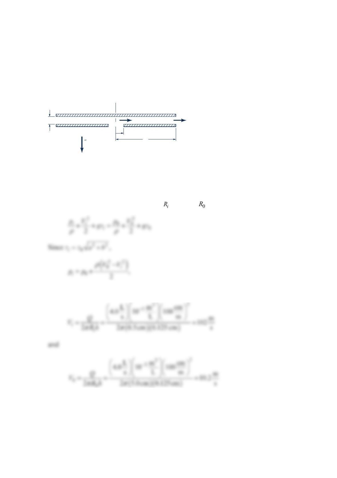
Problem 3.54
Air flows radially outward between the two parallel circular plates shown in the figure
below. The pressure at the outer radius = is atmospheric. Find the pressure at the
inner radius =if the air density is constant, the air flow is inviscid, the volume flow
rate is 4.0 L / s , and the plate spacing is =.
Solution 3.54
Apply Bernoulli’s equation from radius to radius 0
R
.
The volume flow rate Q gives
and
Table B.4 or the ideal gas law gives 3
kg
1.204 m
ρ
= so
h
R
i
R
o
V
o
p
o
=
p
atm
= 101.3 kPa
T
= 20°C
V
i
g
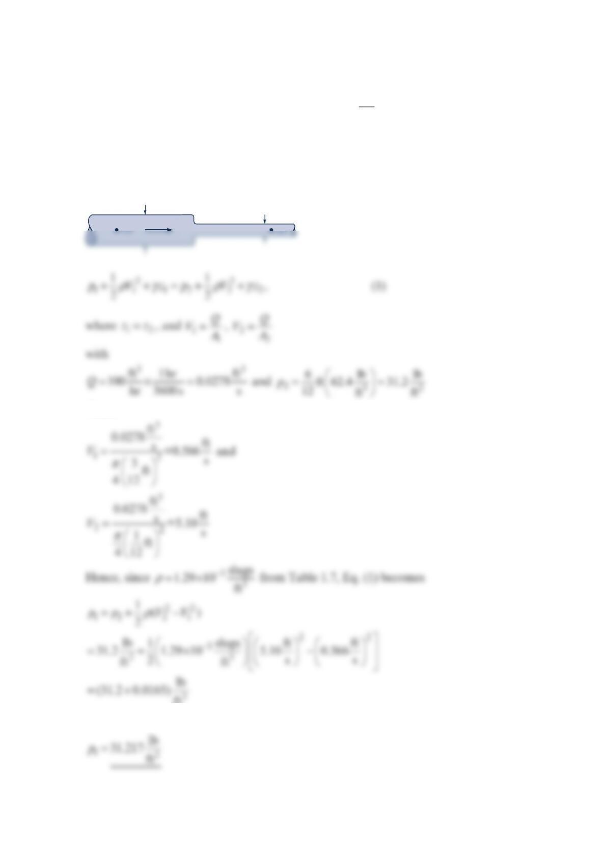
Problem 3.55
Air flows radially inward between the two parallel circular plates shown in the figure below.
The pressure at the outer radius 05.0 cmR= is atmospheric. Find the pressure at the inner
radius 0.5cm
i
R
= if the air density is constant, the air flow is inviscid, the volume flow rate
is 4.0 L / s , and the plate spacing is 0.125cmh=.
Solution 3.55
Apply Bernoulli’s equation from radius to radius .
The volume flow rate Q gives
h
R
i
R
o
V
o
p
o
=
p
atm
= 101.3 kPa
T
= 20°C
V
i
g
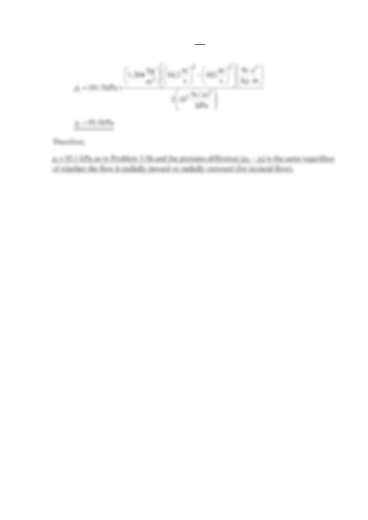
Table B.4 or the ideal gas law gives 3
kg
1.204 m
ρ
= so