PROBLEM 3.15
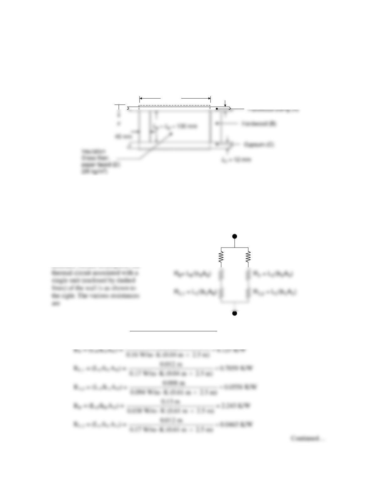
KNOWN: Dimensions and materials associated with a composite wall (2.5 m × 6.5 m, 10 studs each
2.5 m high).
FIND: Wall thermal resistance.
SCHEMATIC:
ASSUMPTIONS: (1) Steady–state, one–dimensional conditions, (2) Planes parallel to x are adiabatic,
(3) Constant properties, (4) Negligible contact resistance.
PROPERTIES: Table A–3 (T ≈ 300 K): Hardwood siding, kA = 0.094 W/m⋅K; Hardwood, kB = 0.16
W/m⋅K; Gypsum, kC = 0.17 W/m⋅K; Insulation (glass fiber paper faced, 28 kg/m3), kD = 0.038
W/m⋅K.
ANALYSIS: Using the
adiabatic surface assumption, the
RA,1 = (LA/kAAB) =
0.008 m
0.8511 K/W
0.094 W/m K (0.04 m 2.5 m) =
⋅×
0.16 W/m K (0.04 m 2.5 m) =
2.243 K/W
0.038 W/m K (0.61 m 2.5 m) =
⋅×
0.13 m
R
A,1
= L
A
/(k
A
A
B
)
R
A,2
= L
A
/(k
A
A
D
)
0.65 m
L
A
= 8 mm
PROBLEM 3.15 (Cont.)
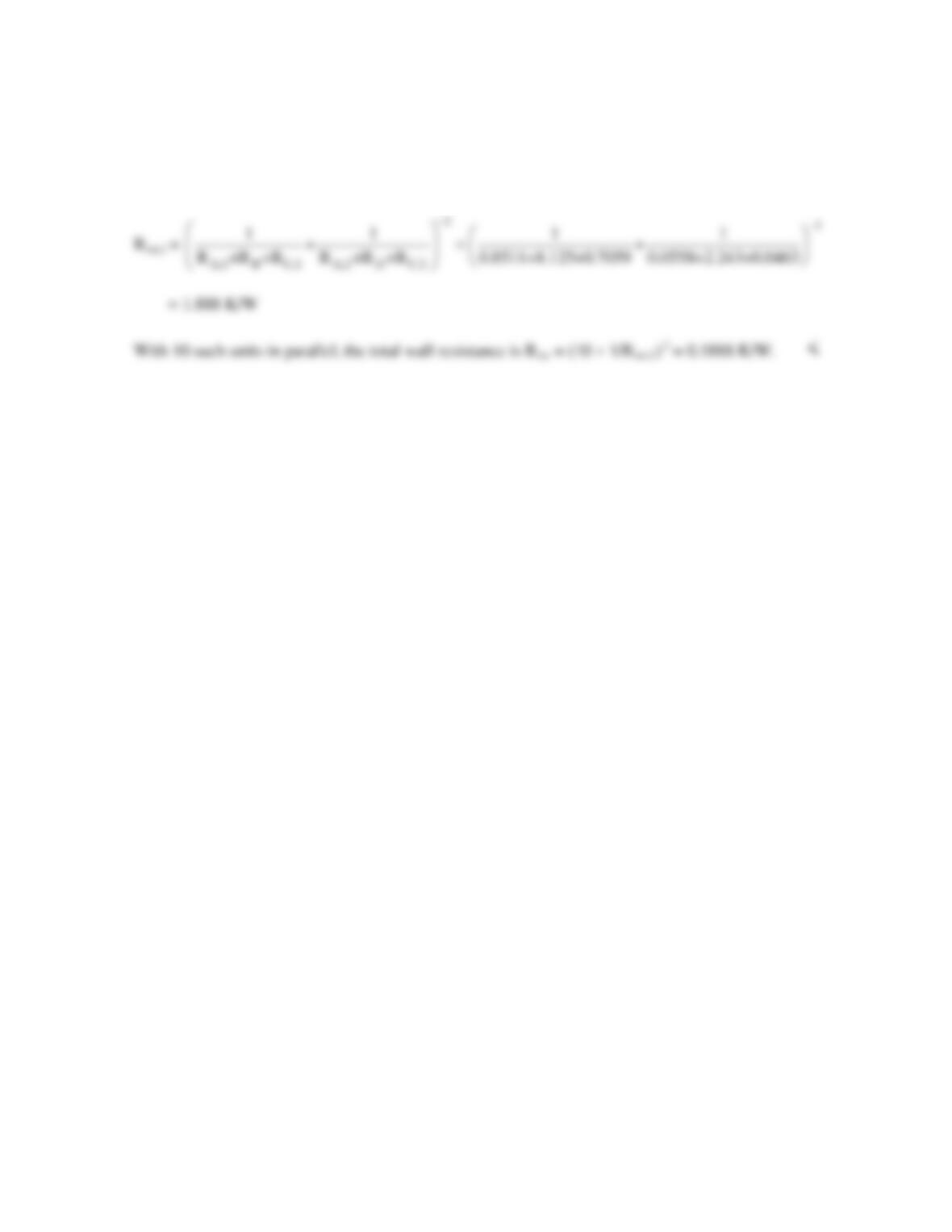
The total unit resistance is
COMMENTS: (1) Contact resistance will increase the overall wall resistance relative to that
calculated here. (2) The total wall resistance assuming isothermal surfaces normal to the x direction is
0.1854 K/W, which is within 2 % of the value found in this solution.
PROBLEM 3.16
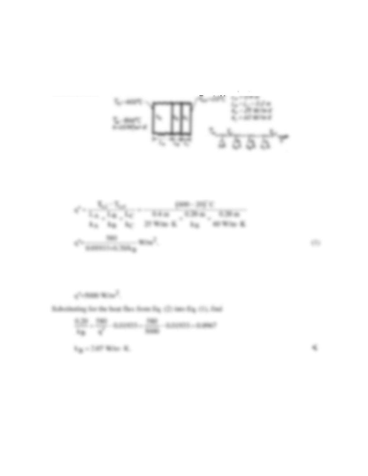
KNOWN: Thicknesses of three materials which form a composite wall and thermal
conductivities of two of the materials. Inner and outer surface temperatures of the composite;
also, temperature and convection coefficient associated with adjoining gas.
FIND: Value of unknown thermal conductivity, kB.
SCHEMATIC:
ASSUMPTIONS: (1) Steady-state conditions, (2) One-dimensional conduction, (3) Constant
properties, (4) Negligible contact resistance, (5) Negligible radiation effects.
ANALYSIS: Referring to the thermal circuit, the heat flux may be expressed as
The heat flux may be obtained from
( )
( )
2
s,i
q =h T T 25 W/m K 800-600 C
∞
′′ −= ⋅
(2)
COMMENTS: Radiation effects might influence the net heat flux at the inner surface of the
oven.
PROBLEM 3.17
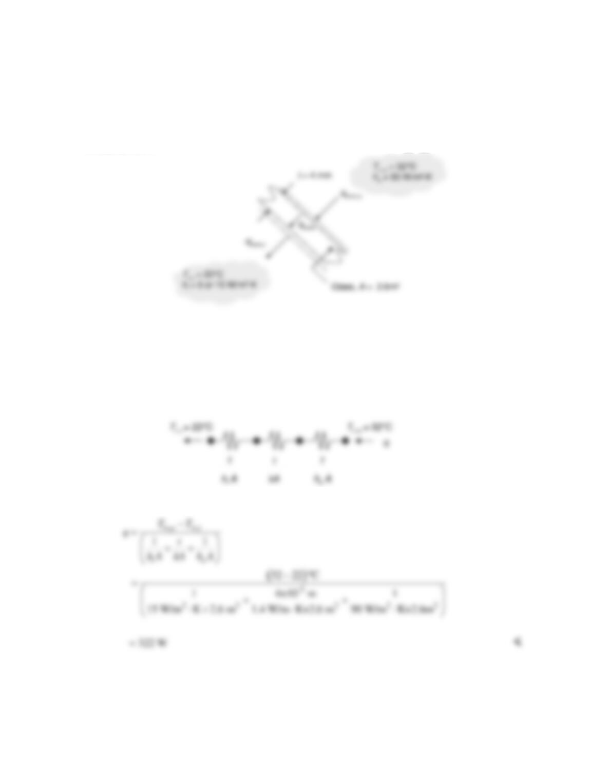
KNOWN: Window surface area and thickness, inside and outside heat transfer coefficients, outside
and passenger compartment temperatures.
FIND: Heat loss through the windows for high and low inside heat transfer coefficients.
SCHEMATIC:
ASSUMPTIONS: (1) Steady–state, one–dimensional conduction. (2) Constant properties. (3)
Negligible radiation.
PROPERTIES: Table A.3, glass (T = 300 K): k = 1.4 W/m⋅K.
ANALYSIS: The thermal circuit is
from which the heat transfer rate through the windows for hi = 15 W/m2⋅K is
Repeating the calculation for hi = 5 W/m2⋅K yields q = 121 W <
Continued…
PROBLEM 3.17 (Cont.)
COMMENTS: (1) Assuming an air conditioner COP of 3, controlling the airflow in the passenger
cabin to reduce the interior convection heat transfer coefficient will reduce the power consumed by the
PROBLEM 3.18
KNOWN: Values of three individual thermal conduction resistances.
FIND: Which conduction resistance should be reduced by half in order to most effectively reduce the
total conduction resistance.
ASSUMPTIONS: (1) Steady–state, one-dimensional conduction, (2) Constant properties.
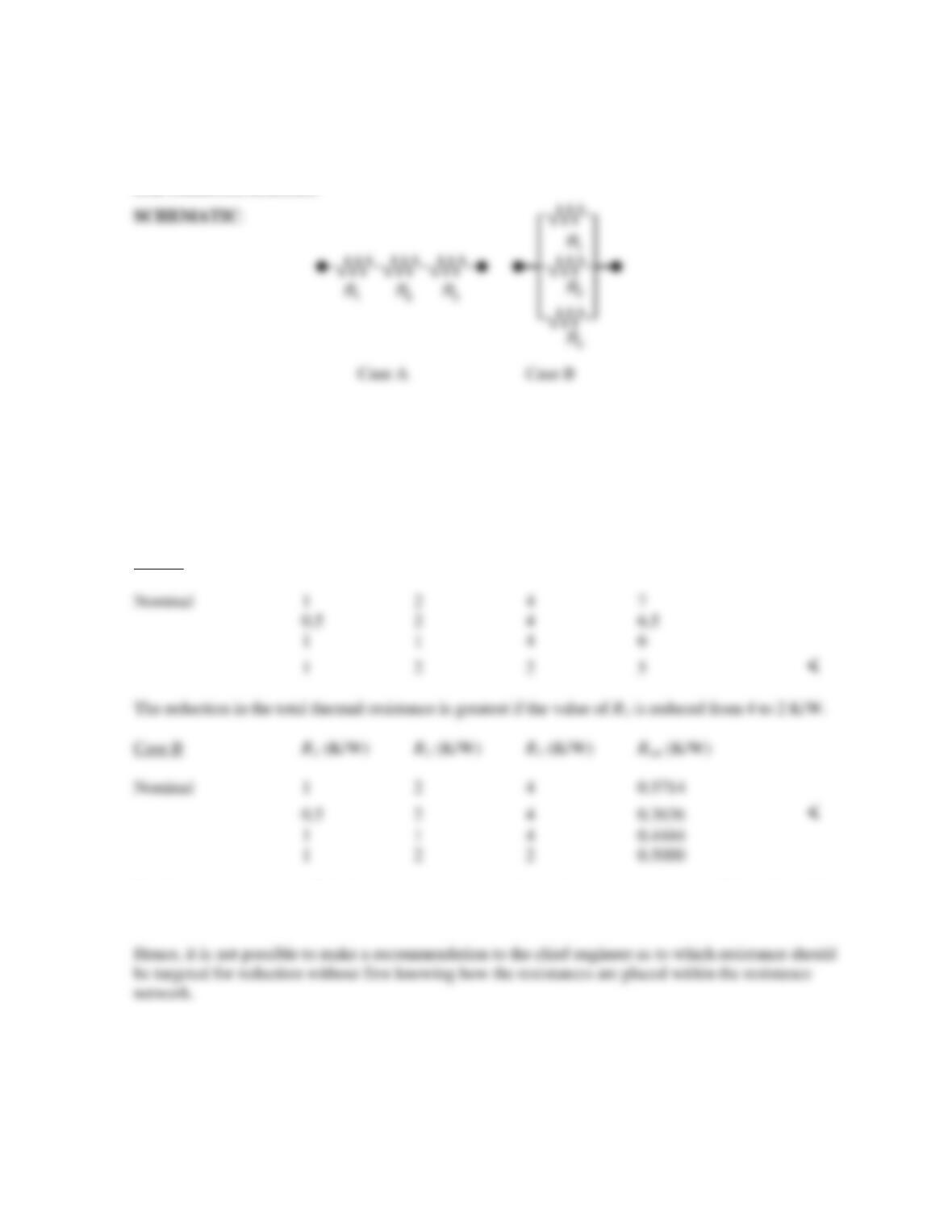
ANALYSIS: We begin with the series resistance network, Case A. The total thermal resistances
associated with the nominal values of the individual thermal resistances, as well as for situations
where the nominal resistance values are reduced by 50%, are presented in the table below.
Case A R1 (K/W) R2 (K/W) R3 (K/W) Rtot (K/W)
For the resistances in parallel, the reduction in the total thermal resistance is greatest if the value of R1
is reduced from 1 to 0.5 K/W.
COMMENTS: A common and serious mistake is to assume that the largest thermal resistance
dominates the thermal resistance network. Although this is sometimes the case, careful analysis will
often reveal quicker, and less expensive alternatives to either reduce or increase the total thermal
resistance.
PROBLEM 3.19
KNOWN: Dimensions of a container of water. Fusion temperature and outer surface
temperature. Initial solidification rate.
FIND: Interfacial thermal resistance shortly after the onset of freezing.
SCHEMATIC:
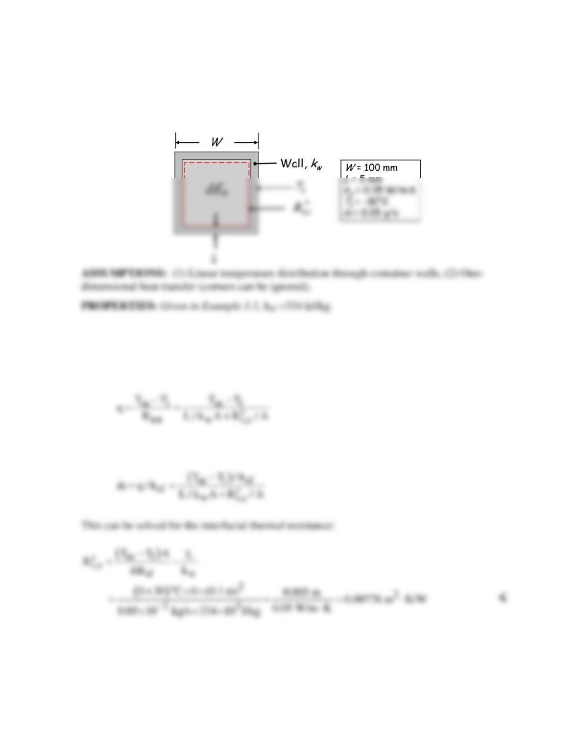
ANALYSIS: The heat transfer rate through the container walls can be related to the total
resistance between the outer wall surface and the ice surface. The total thermal resistance
includes the thermal resistance due to conduction through the wall and the interfacial thermal
resistance at the wall/ice interface.
where Tm is the fusion or melting temperature. The solidification rate,
m,
is given by
COMMENTS: This analysis applies at the initial moment of solidification, when the ice layer
has negligible thickness and thermal resistance. As more ice solidifies, the overall thermal
resistance increases due to the thermal resistance of the thickening layer of ice. The rate of
solidification will therefore decrease with time.
PROBLEM 3.20
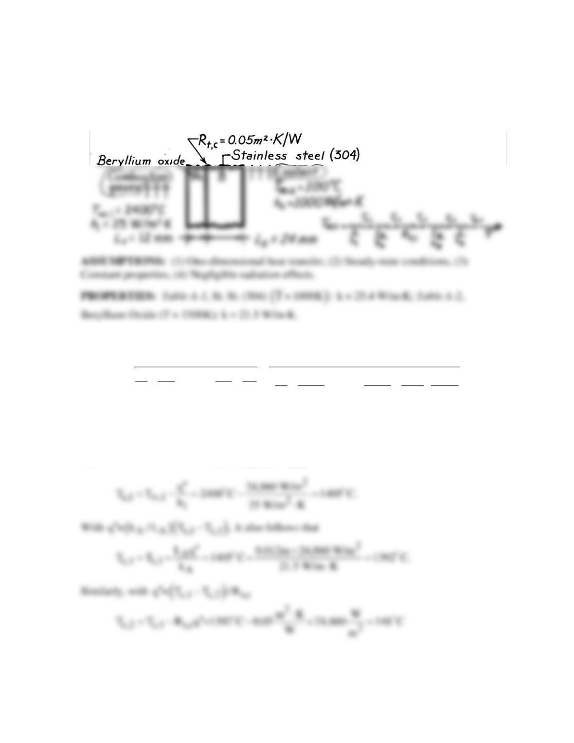
KNOWN: Materials and dimensions of a composite wall separating a combustion gas from a
liquid coolant.
FIND: (a) Heat loss per unit area, and (b) Temperature distribution.
SCHEMATIC:
ANALYSIS: (a) The desired heat flux may be expressed as
( )
,1 ,2
2
AB
t,c
1A B2
TT 2400 100 C
q= LL
11
1 0.012 0.024 1 m .K
R0.05
hk k h 25 21.5 25.4 1000 W
∞∞
−−
′′ =
++ ++ ++++
2
q =24,860 W/m .
′′
<
(b) The composite surface temperatures may be obtained by applying appropriate rate
equations. From the fact that
( )
1 ,1 s,1
q =h T T ,
∞
′′ −
it follows that
Continued …
PROBLEM 3.20 (Cont.)
and with
( )
( )
B B c,2 s,2
q = k /L T T ,
′′ −
2
B
s,2 c,2 B
Lq 0.024m 24,860 W/m
T T 148 C 125 C.
k 25.4 W/m K
′′ ×
=−= − =
⋅
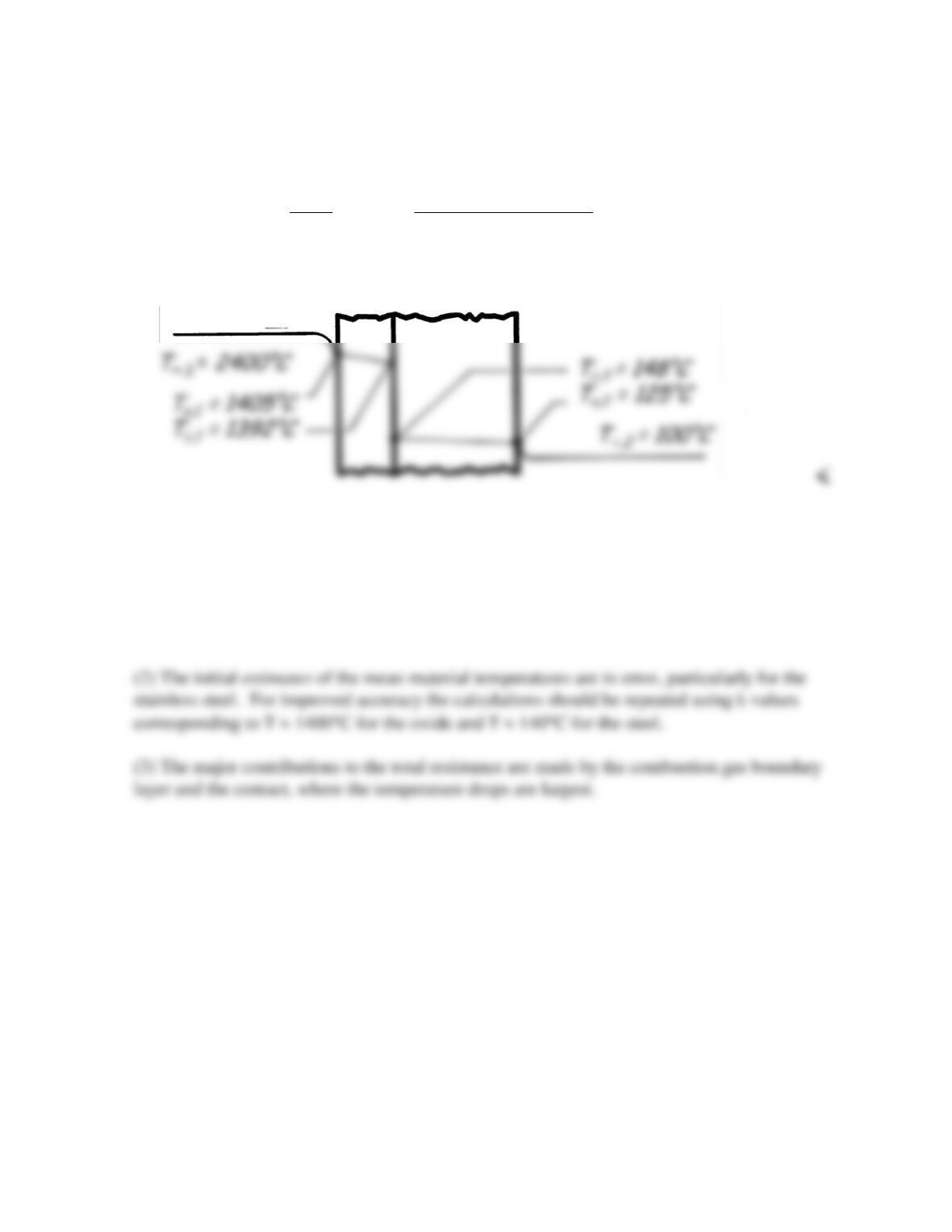
The temperature distribution is therefore of the following form:
COMMENTS: (1) The calculations may be checked by recomputing
q′′
from
( )
( )
22
2 s,2 ,2
q =h T T 1000 W/m K 125-100 C= 25,000 W/m
∞
′′ −= ⋅
The discrepancy is due to roundoff error in the temperature.
PROBLEM 3.21
KNOWN: Thickness, overall temperature difference, and pressure for two stainless steel
plates.
FIND: (a) Heat flux and (b) Contact plane temperature drop.
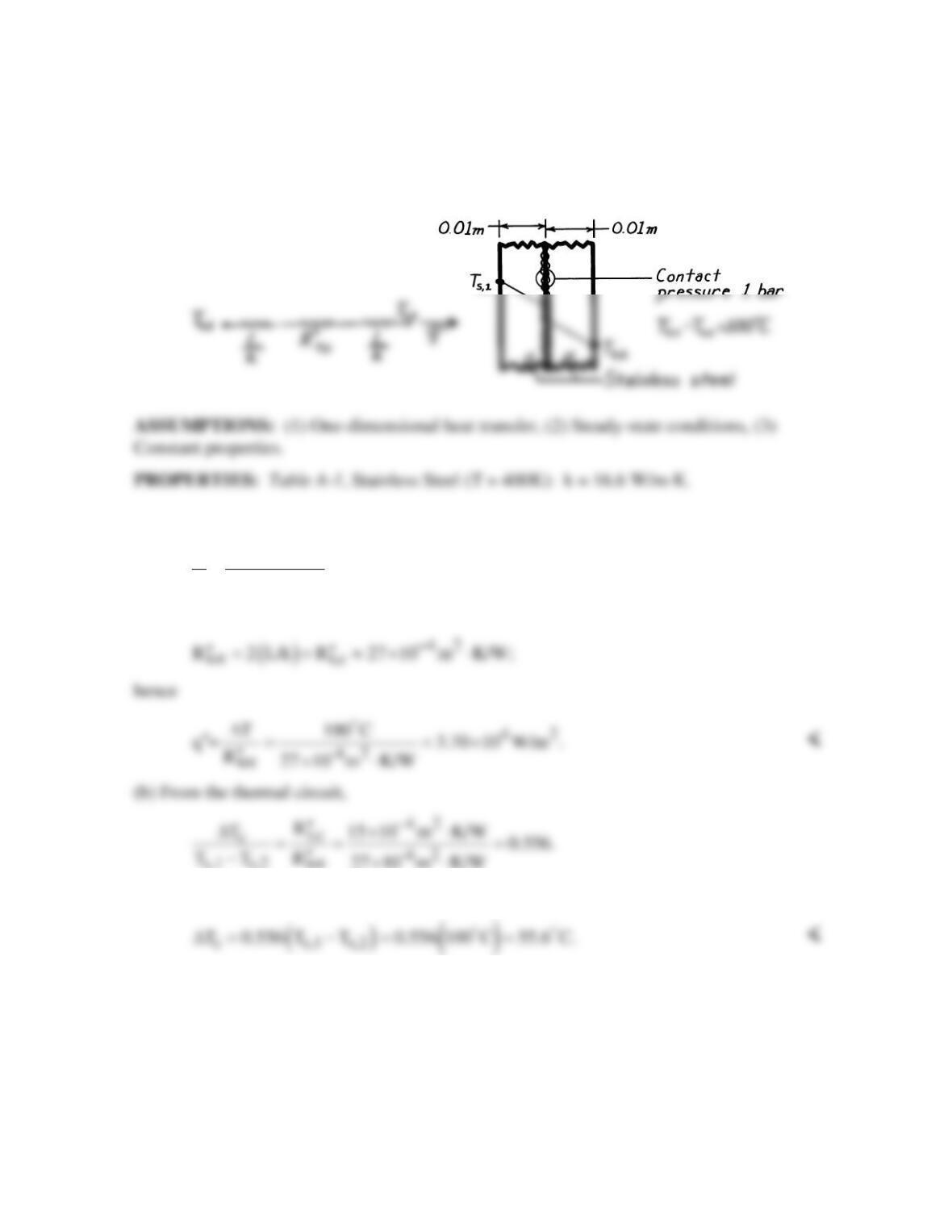
SCHEMATIC:
ANALYSIS: (a) With
42
t,c
R 15 10 m K/W
−
′′ ≈× ⋅
from Table 3.1 and
42
L 0.01m 6.02 10 m K/W,
k 16.6 W/m K
−
= =×⋅
⋅
it follows that
s,1 s,2 tot
Hence,
COMMENTS: The contact resistance is significant relative to the conduction resistances.
The value of
t,c
R′′
would diminish, however, with increasing pressure. Note that there is
considerable uncertainty in the answer since the thermal contact resistance can take on a wide
range of values.
PROBLEM 3.22
KNOWN: Temperatures and convection coefficients associated with fluids at inner and outer
FIND: (a) Rate of heat transfer through the wall, (b) Temperature distribution.
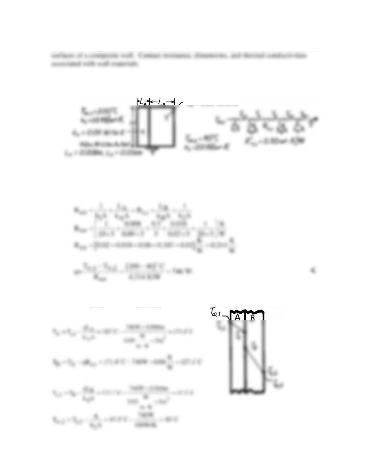
SCHEMATIC:
ASSUMPTIONS: (1) Steady-state conditions, (2) One-dimensional heat transfer, (3)
Negligible radiation, (4) Constant properties.
ANALYSIS: (a) Calculate the total resistance to find the heat rate,
(b) It follows that
s,1 ,1 1
q 746 W
T T 200 C 185.1 C
h A 50 W/K
∞
=−= − =
k
= 0.03 W/m
∙
K
PROBLEM 3.23
KNOWN: Outer and inner surface convection conditions associated with zirconia-coated, Inconel
turbine blade. Thicknesses, thermal conductivities, and interfacial resistance of the blade materials.
Maximum allowable temperature of Inconel.
FIND: Whether blade operates below maximum temperature. Temperature distribution in blade, with
and without the TBC.
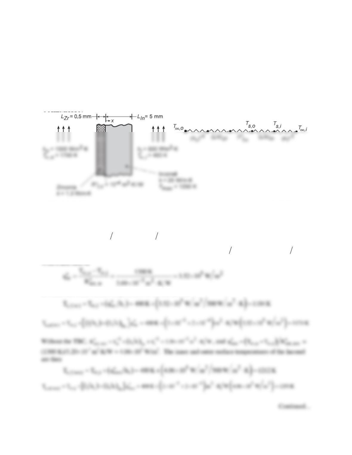
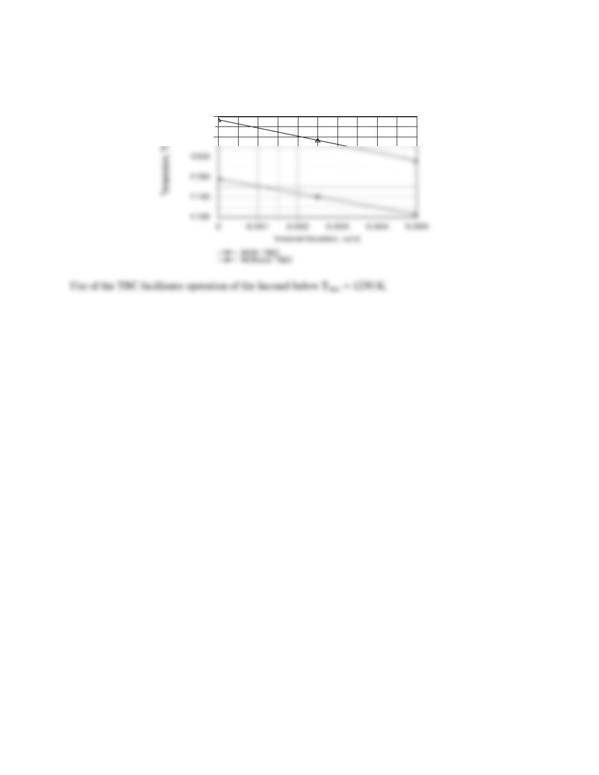
SCHEMATIC:
ASSUMPTIONS: (1) One-dimensional, steady-state conduction in a composite plane wall, (2) Constant
properties, (3) Negligible radiation.
ANALYSIS: For a unit area, the total thermal resistance with the TBC is
( ) ( )
11
tot,w o t,c i
Zr In
R h Lk R Lk h
−−
′′ ′′
=+ ++ +
()
3 44432 32
tot,w
R 10 3.85 10 10 2 10 2 10 m K W 3.69 10 m K W
− −−−− −
′′ = + × + +× +× ⋅ = × ⋅
the inner and outer surface temperatures of the Inconel are
PROBLEM 3.23 (Cont.)
1260
1300
COMMENTS: Since the durability of the TBC decreases with increasing temperature, which increases
with increasing thickness, limits to the thickness are associated with reliability considerations.
PROBLEM 3.24
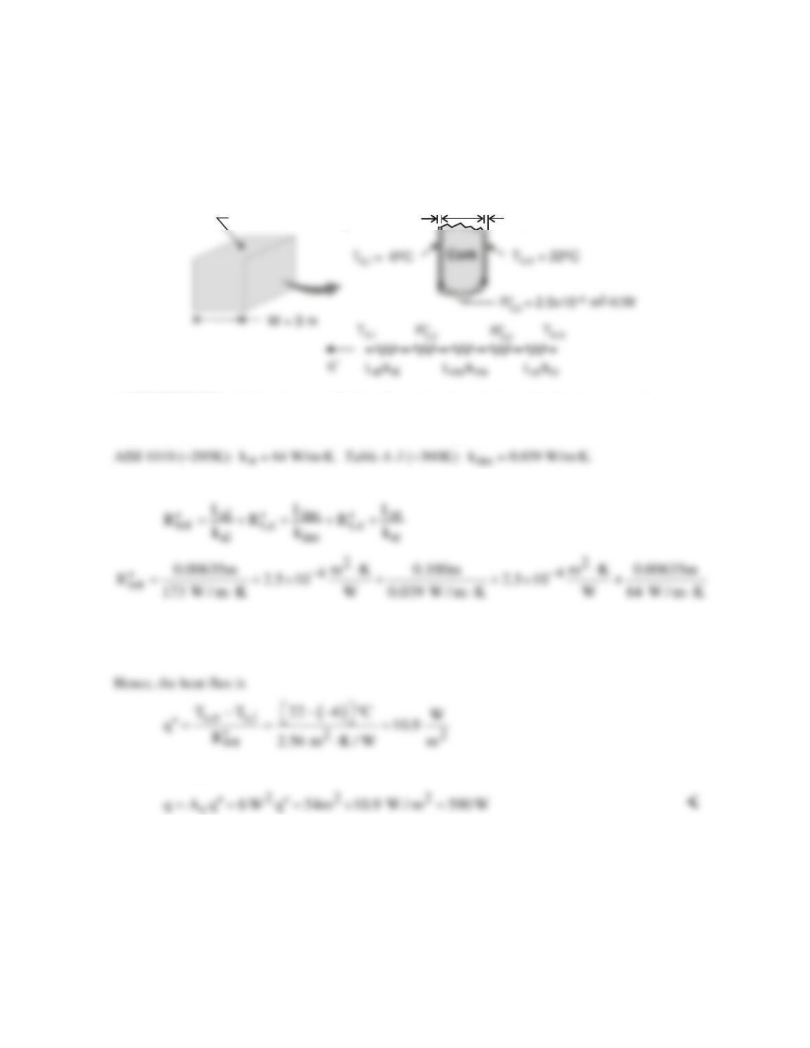
KNOWN: Size and surface temperatures of a cubical freezer. Materials, thicknesses and interface
resistances of freezer wall.
FIND: Cooling load.
SCHEMATIC:
L = 100 mm
ins
L = 6.35 mm
st
L = 6.35 mm
al
Freezer
ASSUMPTIONS: (1) Steady-state, (2) One-dimensional conduction, (3) Constant properties.
PROPERTIES: Table A-1, Aluminum 2024 (~267K): kal = 173 W/m⋅K. Table A-1, Carbon steel
ANALYSIS: For a unit wall surface area, the total thermal resistance of the composite wall is
()
5 4 4 52 2
tot
R 3.7 10 2.5 10 2.56 2.5 10 9.9 10 m K / W 2.56 m K / W
−− −−
′′ = × +× + +× +× ⋅ = ⋅
and the cooling load is
COMMENT: Thermal resistances associated with the cladding and the adhesive joints are negligible
compared to that of the insulation.
PROBLEM 3.25
KNOWN: Operating conditions, measured temperatures and heat input, and theoretical thermal
conductivity of a carbon nanotube.
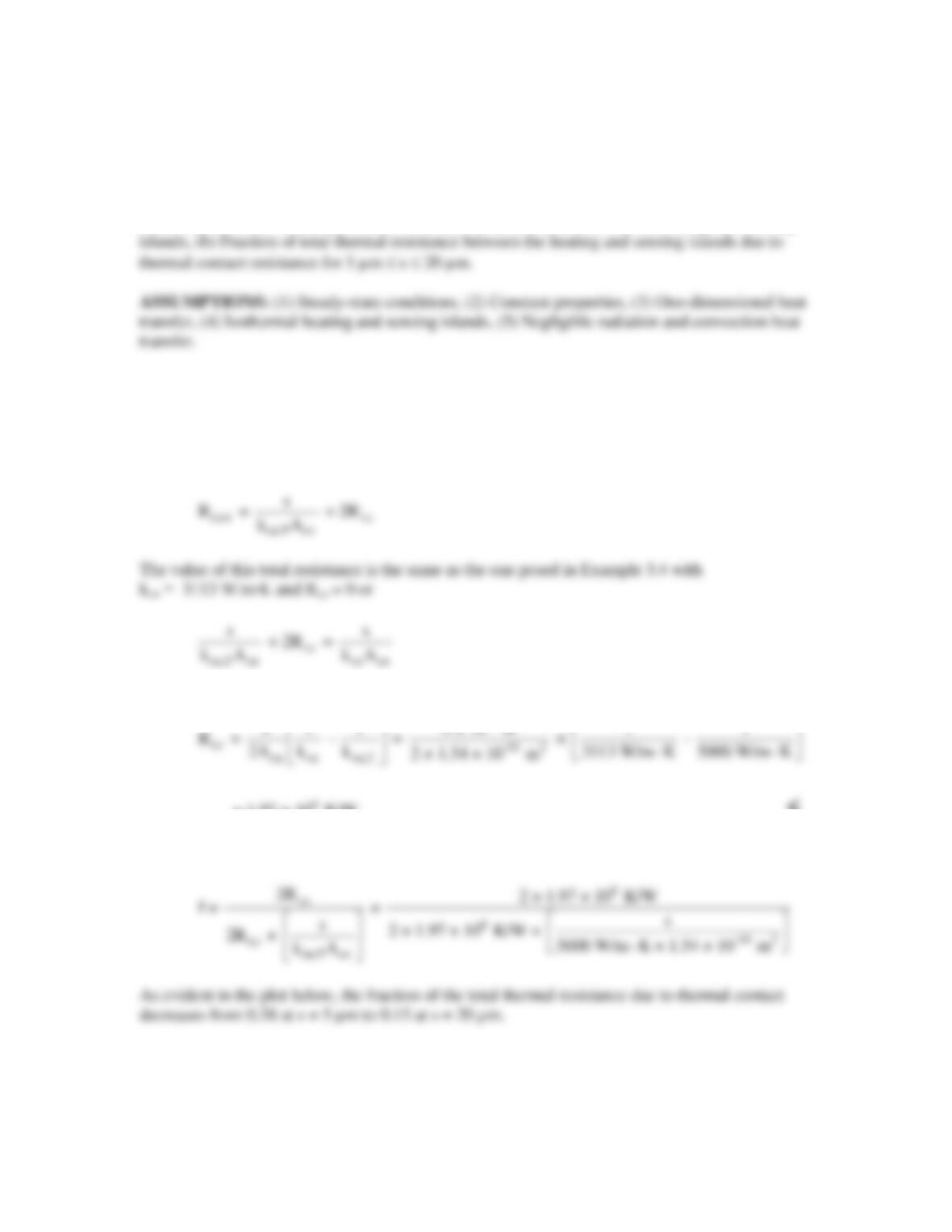
FIND: (a) Thermal contact resistance between the carbon nanotube and the heating and sensing
PROPERTIES: kcn,T = 5000 W/m∙K
ANALYSIS:
(a) The total thermal resistance between the heated and sensing island is
for which
-6
= 1.97 × 10 K/W
<
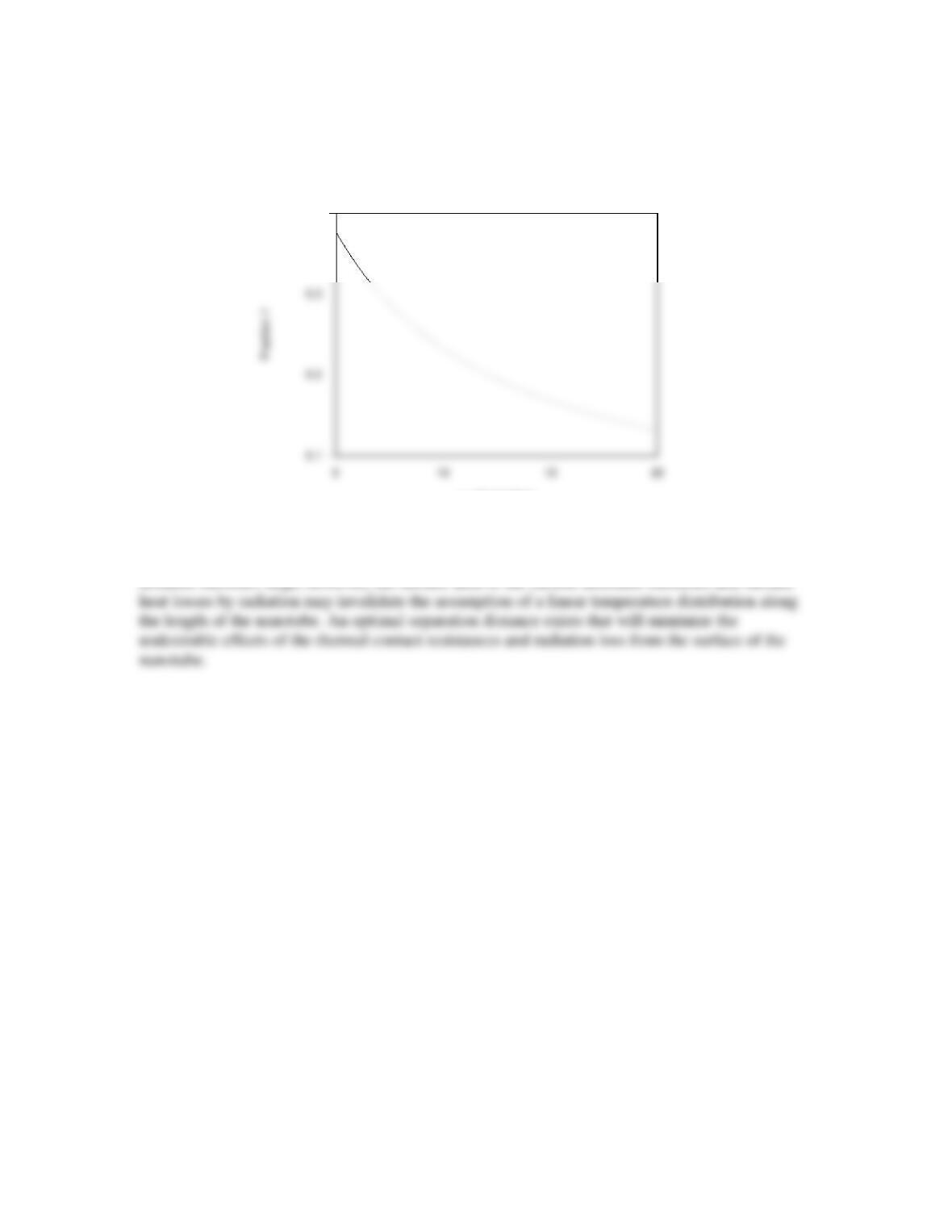
(b) The fraction of the total resistance due to the thermal contact resistance is
Continued…
PROBLEM 3.25 (Cont.)
Fraction of Thermal Resistance due to Contact
s, micrometers
0.4
COMMENT: To desensitize the experiment to uncertainty due to the unknown thermal contact
resistance values, a large separation distance between the islands is desired. As the separation
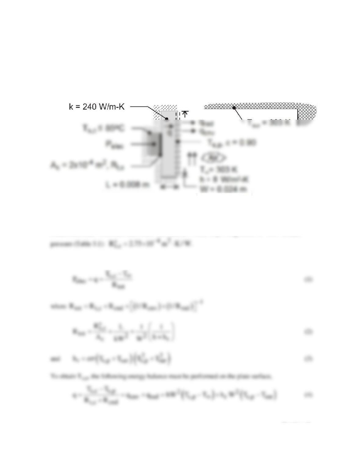
PROBLEM 3.26
KNOWN: Dimensions, thermal conductivity and emissivity of base plate. Temperature and
convection coefficient of adjoining air. Temperature of surroundings. Maximum allowable
temperature of transistor case. Case–plate interface conditions.
FIND: (a) Maximum allowable power dissipation for an air-filled interface, (b) Effect of convection
coefficient on maximum allowable power dissipation.
SCHEMATIC:
ASSUMPTIONS: (1) Steady-state, (2) Negligible heat transfer from the enclosure, to the
surroundings. (3) One-dimensional conduction in the base plate, (4) Radiation exchange at surface of
base plate is with large surroundings, (5) Constant thermal conductivity.
PROPERTIES: Aluminum–aluminum interface, air–filled, 10 µm roughness, 105 N/m2 contact
ANALYSIS: (a) With all of the heat dissipation transferred through the base plate,
Continued …
PROBLEM 3.26 (Cont.)
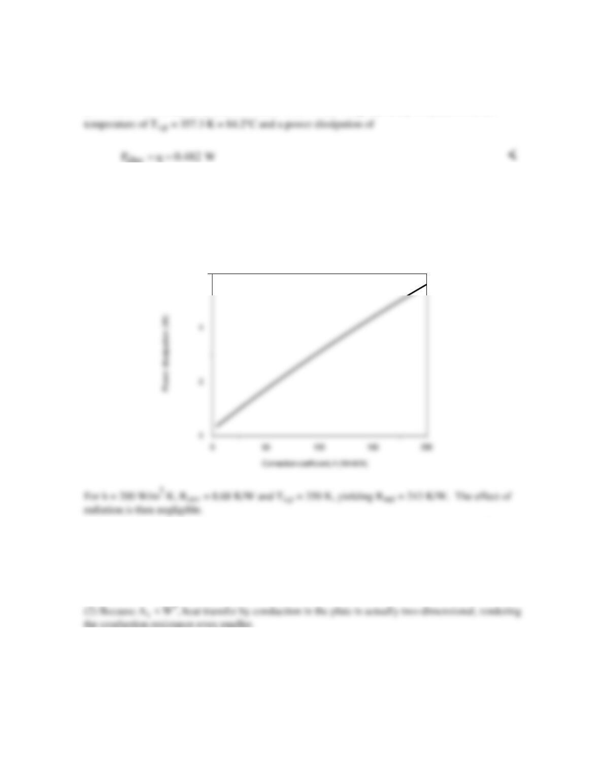
With Rt,c = 2.75 × 10⁻⁴ m2⋅K/W/2×10-4 m2 = 1.375 K/W, Rcnd = 0.008 m/(240 W/m⋅K × 5.76 × 10⁻⁴
m2) = 0.0579 K/W, and the prescribed values of h, W, T∞ = Tsur and ε, Eq. (4) yields a surface
elec
The convection and radiation resistances are Rcnv = 217 K/W and Rrad = 235 K/W, where hr = 7.40
W/m2⋅K.
(b) With the major contribution to the total resistance made by convection, significant benefit may be
derived by increasing the value of h.
6
COMMENTS: (1) The plate conduction resistance is negligible, and even for h = 200 W/m2⋅K, the
contact resistance is small relative to the convection resistance. However, Rt,c could be rendered
negligible by using indium foil, instead of an air gap, at the interface. From Table 3.1,
42
t,c
R 0.07 10 m K / W,
−
′′ =×⋅
in which case Rt,c = 0.035 m⋅K/W.
PROBLEM 3.27
KNOWN: Oak wood with a grain structure. Grains are highly porous and the wood is dry.
FIND: Fraction of oak cross–section that appears as being grained.
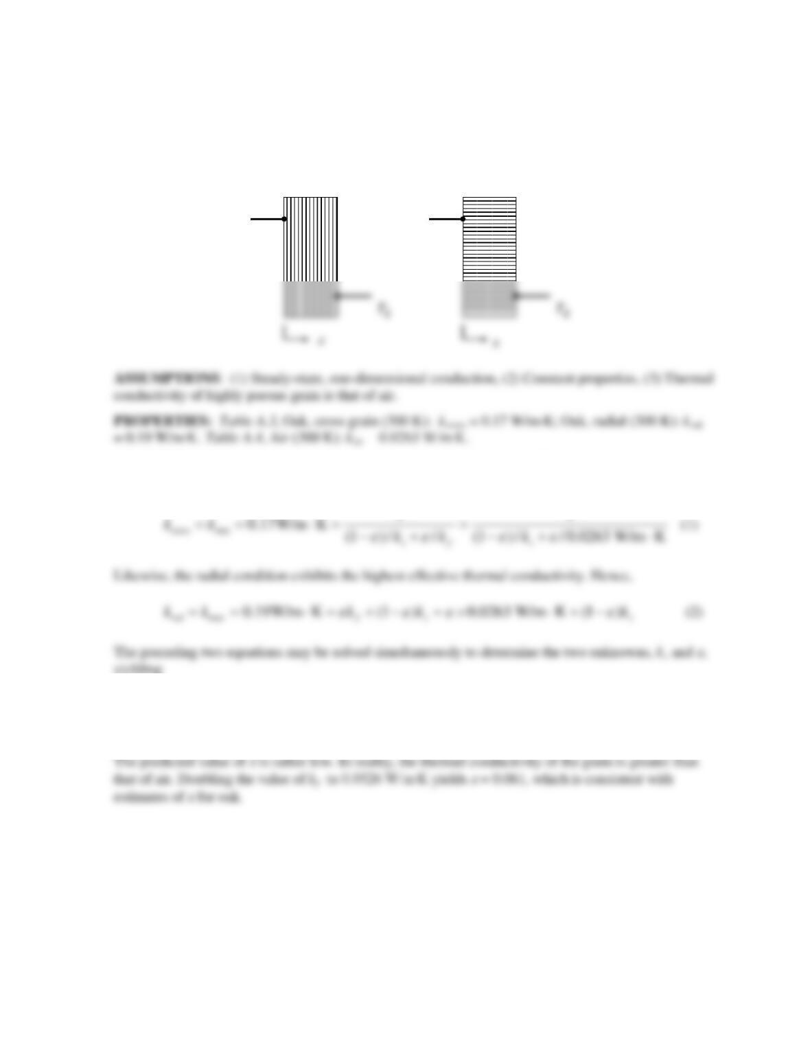
SCHEMATIC:
ANALYSIS: The cross grain condition is characterized by the lowest effective thermal conductivity.
Therefore,
ε
= 0.022 <
COMMENTS: (1) The predicted value of the solid thermal conductivity is ks = 0.1937 W/m∙K. (2)
T1T1
Cross grain Radial
PROBLEM 3.28
KNOWN: Density of glass fiber insulation.
FIND: Maximum and minimum possible values of the effective thermal conductivity of the insulation
at T = 300 K, and comparison with the value listed in Table A.3.
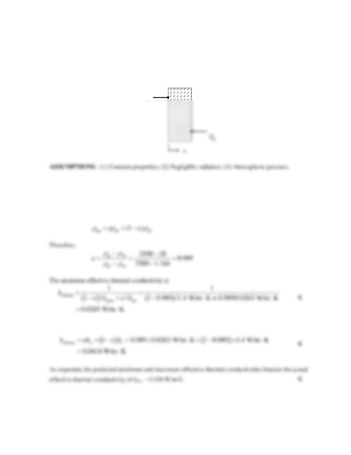
SCHEMATIC:
T
PROPERTIES: Table A.3, Glass (plate): kgl = 1.4 W/m∙K,
r
gl = 2500 kg/m3.Glass fiber batt (paper
faced,
r
ins = 28 kg/m3) kins = 0.038 W/m∙K. Table A.4, Air (300 K): kair = 0.0263 W/m∙K,
r
air = 1.1614
kg/m3. Given:
r
ins = 28 kg/m3.
ANALYSIS: The density of the glass fiber insulation may be related to the density of the air and
glass phases, and the volume fraction,
ε
, as follows.
The maximum effective thermal conductivity is
COMMENT: Radiation internal to the glass fiber batting may be significant. If so, this will reduce
the insulating capability of the matt.