
Chap. 3 Soil Mechanics
3.1 Explain the difference between moisture content and degree of saturation.
Solution
Moisture content of a soil is the ratio of the weight of its water to weight of its solids, whereas
Chap. 3 Soil Mechanics
3.2 A certain saturated sand (S = 100%) has a moisture content of 25.1% and a specific gravity of
solids of 2.68. It also has a maximum index void ratio of 0.84 and a minimum index void ratio
of 0.33. Compute its relative density and classify its consistency.
Solution
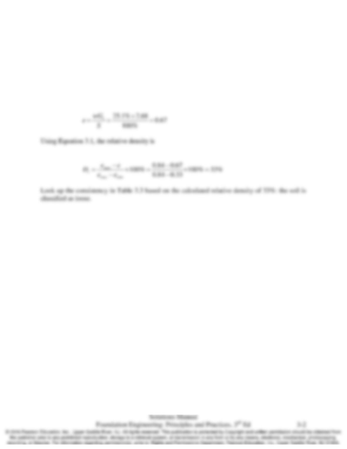
First we must compute the void ratio e using the given specific gravity and moisture content. The
void ratio calculated using specific gravity and moisture content is

Chap. 3 Soil Mechanics
3.3 Consider a soil that is being placed as a fill and compacted using a sheepsfoot roller (a piece of
construction equipment). Will the action of the roller change the void ratio of the soil? Explain.
Solution
Yes, whenever a soil is compacted, the volume of the soil decreases. Since the volume of the
Chap. 3 Soil Mechanics
3.4 A sample of soil has a volume of 0.45 ft3 and a weight of 53.3 lb. After being dried in an oven, it
has a weight of 45.1 lb. It has a specific gravity of solids of 2.70. Compute its moisture content
and degree of saturation before it was placed in the oven.
Solution
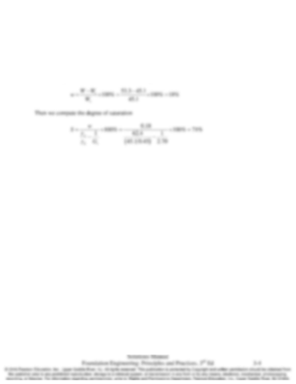
First we compute the moisture content of the sample
Chap. 3 Soil Mechanics
3.5 A site is underlain by a soil that has a unit weight of 18.7 kN/m3 above the groundwater table and
19.9 kN/m3 below. The groundwater table is located at a depth of 3.5 m below the ground
surface. Compute the total vertical stress, pore water pressure, and effective vertical stress at the
following depths below the ground surface:
a. 2.2 m
b. 4.0 m
c. 6.0 m
Solution
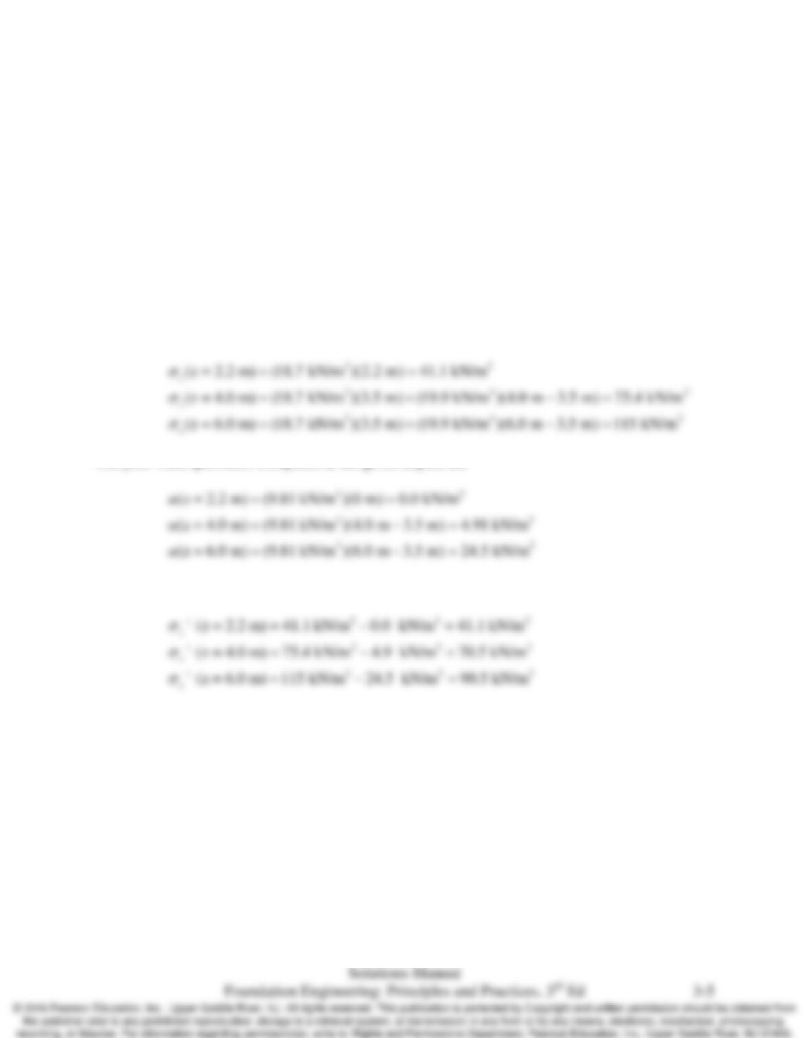
Using Equation 3.3, the total vertical stresses computed at the given depths are
The pore water pressures computed at the given depths are
Using Equation 3.5, the effective vertical stresses computed at the given depths are
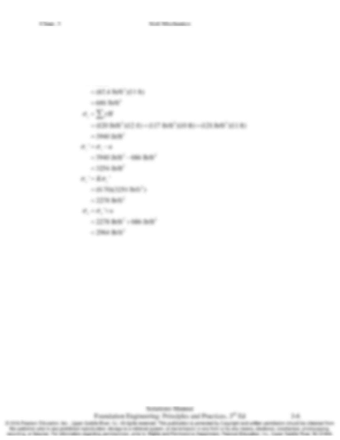
3.6 The subsurface profile at a certain site is shown in Figure 3.20. Compute u, σx, σz, σʹx, and σʹz at
Point A.
Solution
ww
uz
γ
=
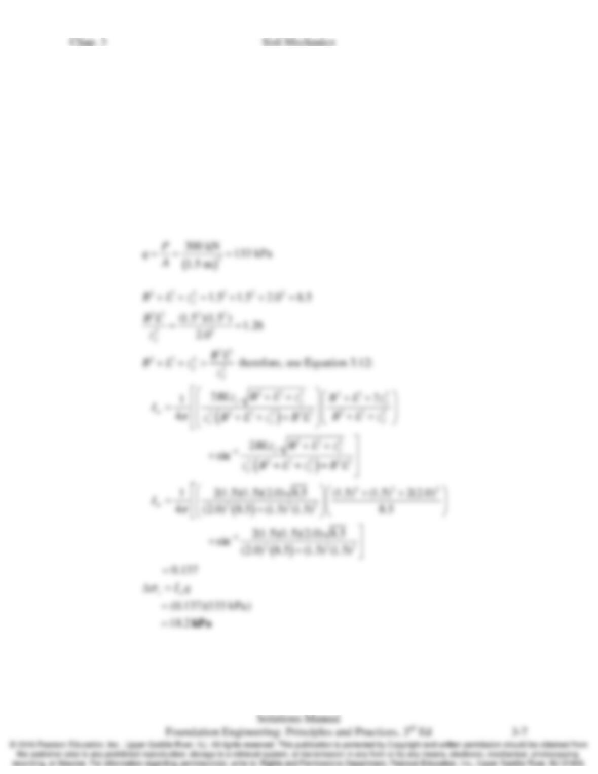
3.7 The vertical load of 300 kN is applied to a 1.5 m × 1.5 m area at the ground surface that is level.
a. Compute the induced vertical stress, Δσz, at a point 2.0 m below the corner of this
square loaded area.
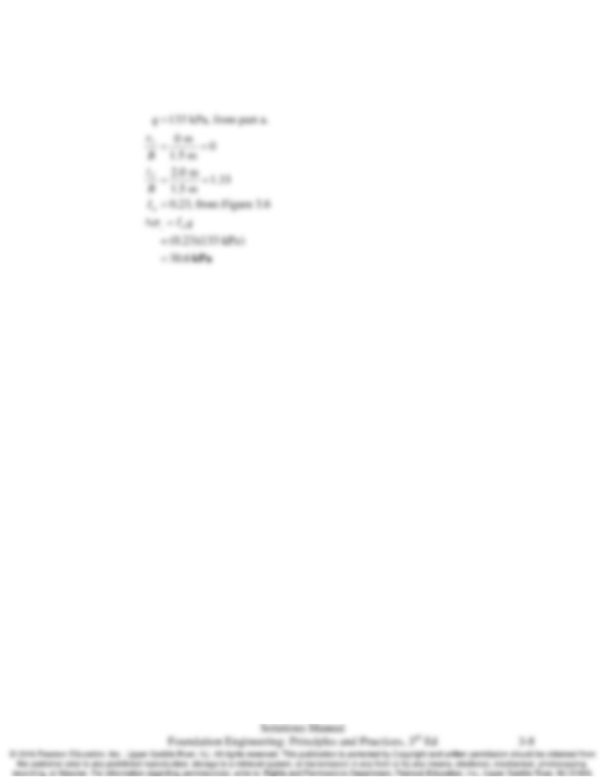
b. Compute the induced vertical stress, Δσz, at a point 2.0 m below the center of this
square loaded area.
Solution
a. This solution uses the Newman solution to the Boussinesq’s Method to compute the
induced stress; there are many other methods to solve this problem.
Chap. 3 Soil Mechanics
b. This solution uses the chart method to compute the induced stress; this problem can
also be solved by other methods.
Chap. 3 Soil Mechanics
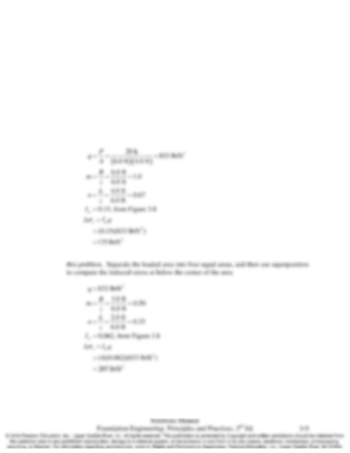
3.8 A vertical load of 20 k is applied to a 6.0 ft × 4.0 ft area at the ground surface that is level.
a. Compute the induced vertical stress, Δσz, at a point 6.0 ft below the corner of this
rectangular loaded area.
b. Compute the induced vertical stress, Δσz, at a point 6.0 ft below the center of this
rectangular loaded area.
Solution
a. This solution uses Figure 3.8 for a chart solution; there are many other methods to solve
this problem.
b. This solution uses Figure 3.8 for a chart solution; there are many other methods to solve
Chap. 3 Soil Mechanics
3.9 A 3 m × 3 m footing is to be built on the surface of a 15 m thick layer of unsaturated sand. The
sand is underlain by a very dense gravel layer. The water table is at a great depth. The sand is
relative uniform and in situ testing indicates it has a constrained modulus of 10 MPa. The
footing load is 200 kN. Compute the settlement under the center of the footing.
Solution
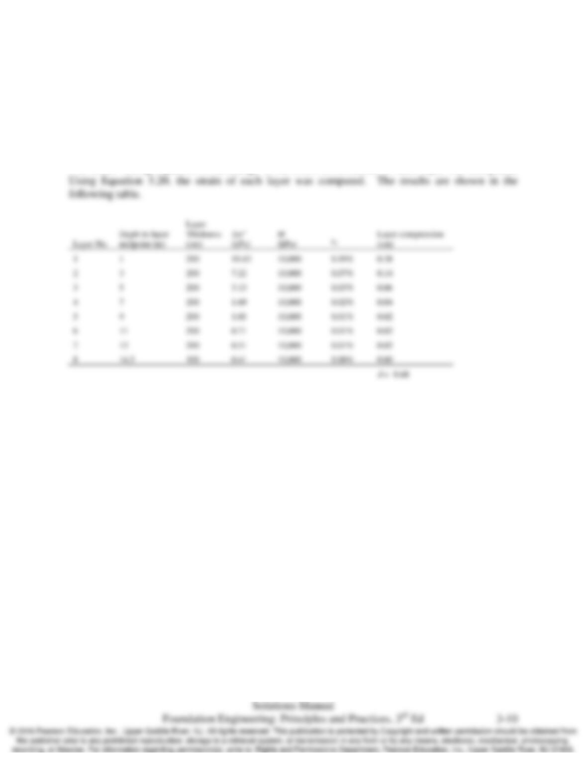
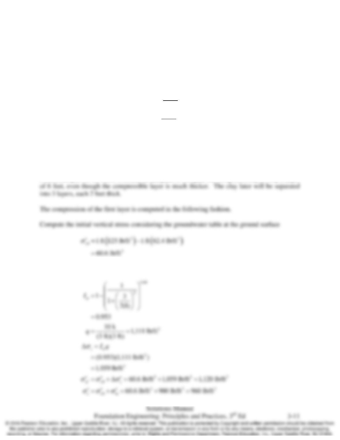
The sand was separated into 8 layers each 2 m thick with the exception of layer no. 8 which was
1 m thick. Using Equation 3.14, change in the stress at the center of each layer was computed.
Chap. 3 Soil Mechanics
3.10 A 3–foot square footing carries a sustained load of 10 k. It is placed on the surface of a 30 foot
thick saturated overconsolidated clay underlain by dense sand. Based on laboratory tests, the
clay can be adequately modeled using the e–log–p method. The laboratory tests provide the
following compressibility information for the clay:
γ
= 123 lb/ft3
0
1
c
C
e+
= 0.06
0
1
r
C
e+
= 0.002
σʹm = 900 lb/ft2
The groundwater table is located at the ground surface. Compute the settlement of the
footing.
Solution
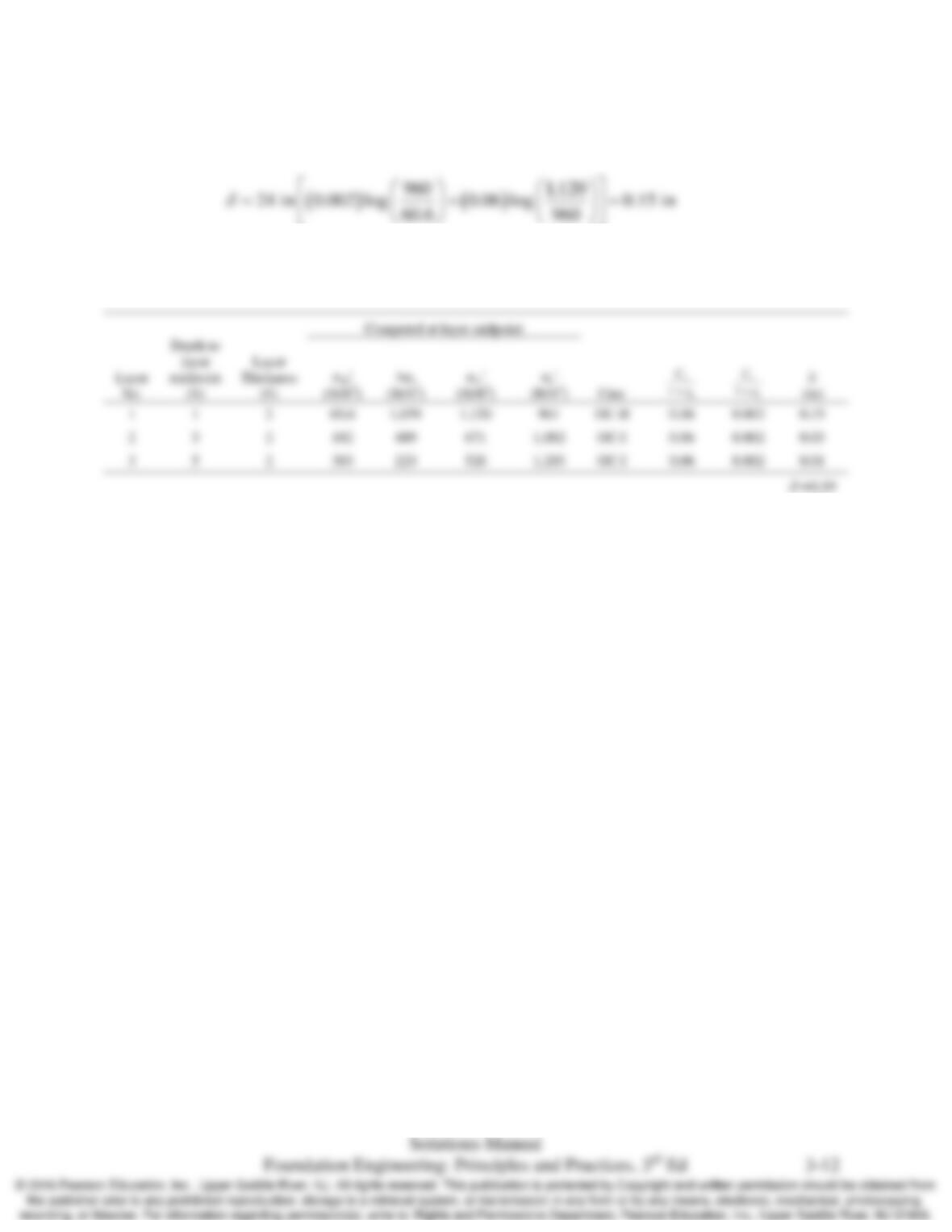
From Example 3.5 we know it should be adequate to compute the compressibility to only a depth
Using Equation 3.14 to compute the induced stress:
Chap. 3 Soil Mechanics
Since σʹzf > σʹc , this is case OC–II and the layer compression is computed using Equation 3.31:
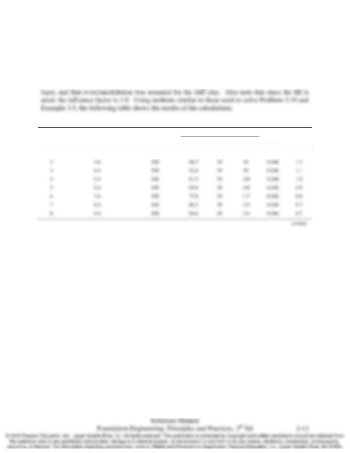
This process is repeated for the remaining layers. The following table shows the results of the
calculations.
Chap. 3 Soil Mechanics
3.11 A 2m thick fill is to be placed on the soil shown in Figure 3.21. Once it is compacted this fill
will have a unit weight of 19.5 kN/m3. Compute the ultimate consolidation settlement.
Solution
Note that the sand layer is dense, its consolidation is negligible compared to that of the stiff clay
Computed at layer midpoint
Layer No.
Depth to layer midpoint (m)
Layer Thickness (cm)
σz0ʹ
(kPa)
∆σz
(kPa)
σzfʹ
(kPa)
0
1r
C
e+
δ
(cm)
1
2.4
100
35.9
39
75
0.046
1.5
2
3.4
100
44.2
39
83
0.046
1.3
3
4.4
100
52.6
39
92
0.046
1.1
4
5.4
100
61.0
39
0.046
1.0
5
6.4
100
69.4
39
0.046
0.9
6
7.4
100
77.8
39
0.046
0.8
7
8.4
100
86.2
39
0.046
0.7
8
9.4
100
94.6
39
0.046
0.7

3.12 Estimate the effective friction angle of the following soils:
a. Silty sand with dry unit weight of 100
3
lb/ft
.
b. Poorly-graded gravel with relative density of 70%.
c. Very dense well-graded sand.
Solution
Using Figure 3.14, estimate the effective friction angle of the given soils
Chap. 3 Soil Mechanics
3.13 Explain the difference between the drained condition and the undrained condition.
Solution
• Drained condition is a condition where excess pore water does not exist under change in
loading. In other words, the pore water pressure is equal to the hydrostatic pore water

Chap. 3 Soil Mechanics
3.14 A soil has cʹ = 5 kPa and
ϕ
ʹ = 32°. The effective stress at a point in the soil is 125 kPa. Compute
the shear strength normal to this stress at this point.
Solution
Using Equation 3.32, compute the shear strength
Chap. 3 Soil Mechanics
3.15 A footing with an embedment of 2 m is embedded in a sand with a unit weight of 125 lb/ft3 and a
ϕ
ʹ of 36°. If the footing is subjected to a horizontal load that causes it to move horizontally,
compute the total active and passive resultant forces acting on the footing.
Solution
Using Equation 3.38, compute the active resultant force
3.16 The soil profile at a certain site is as follows:
Depth (ft)
γ
(lb/ft3) cʹ (lb/ft2)
ϕ
ʹ (degree) Su(lb/ft2)
0-12 119 1000
12–20 126 200 20
20–32 129 0 32
The groundwater table is at a depth of 15 ft.
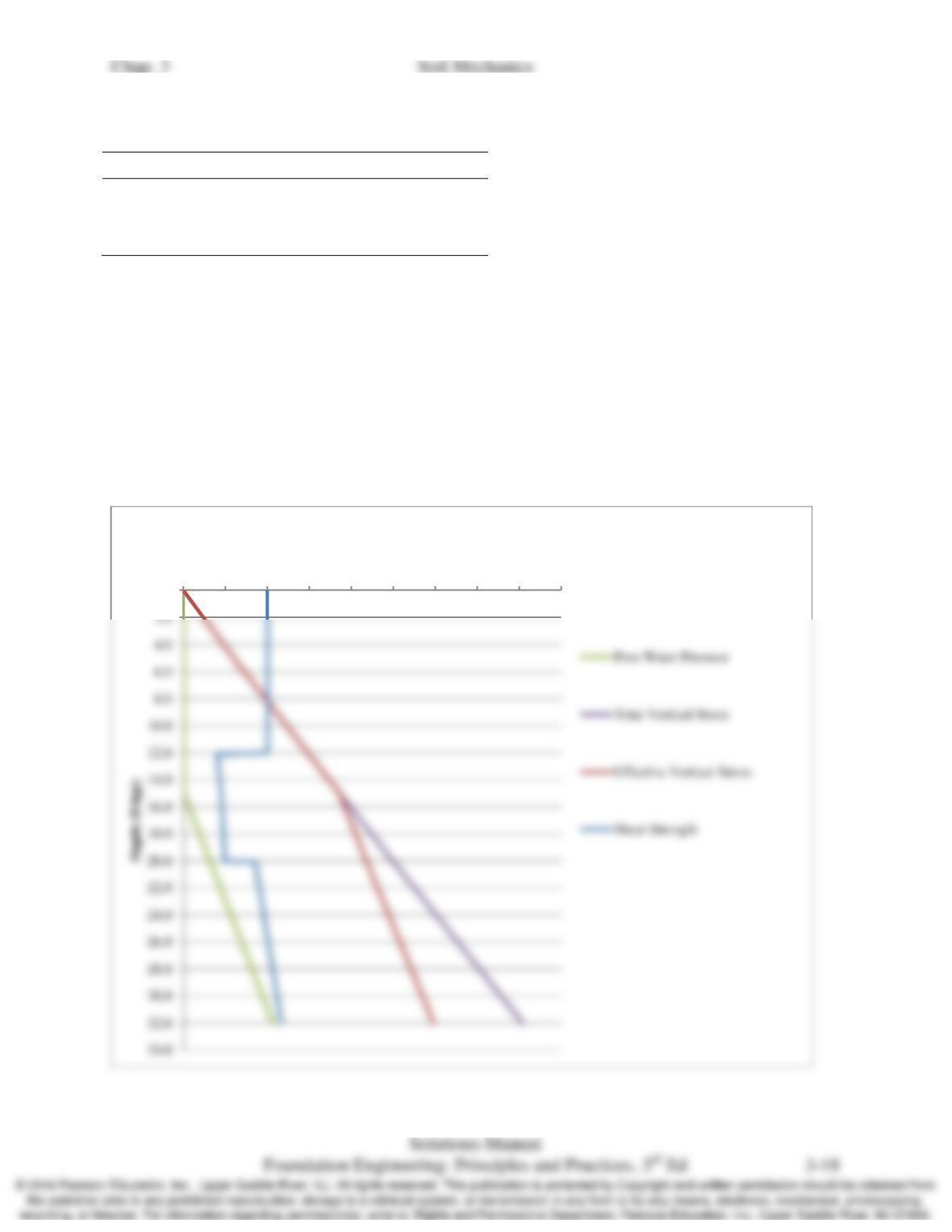
Develop plots of pore water pressure, total vertical stress, effective total stress, and shear
strength on a horizontal plane vs. depth. All four of these plots should be superimposed on the
same diagram with the parameters on the horizontal axis (increasing to the right) and depth on
the vertical axis (increasing downward).
Hint: Because the cohesion and friction angle suddenly change at the strata boundaries, the shear
strength also may change suddenly at these depths.
Solution
0.0
0
500
1000
1500
2000
2500
3000
3500
4000
4500
(lb/ft2)
Chap. 3 Soil Mechanics
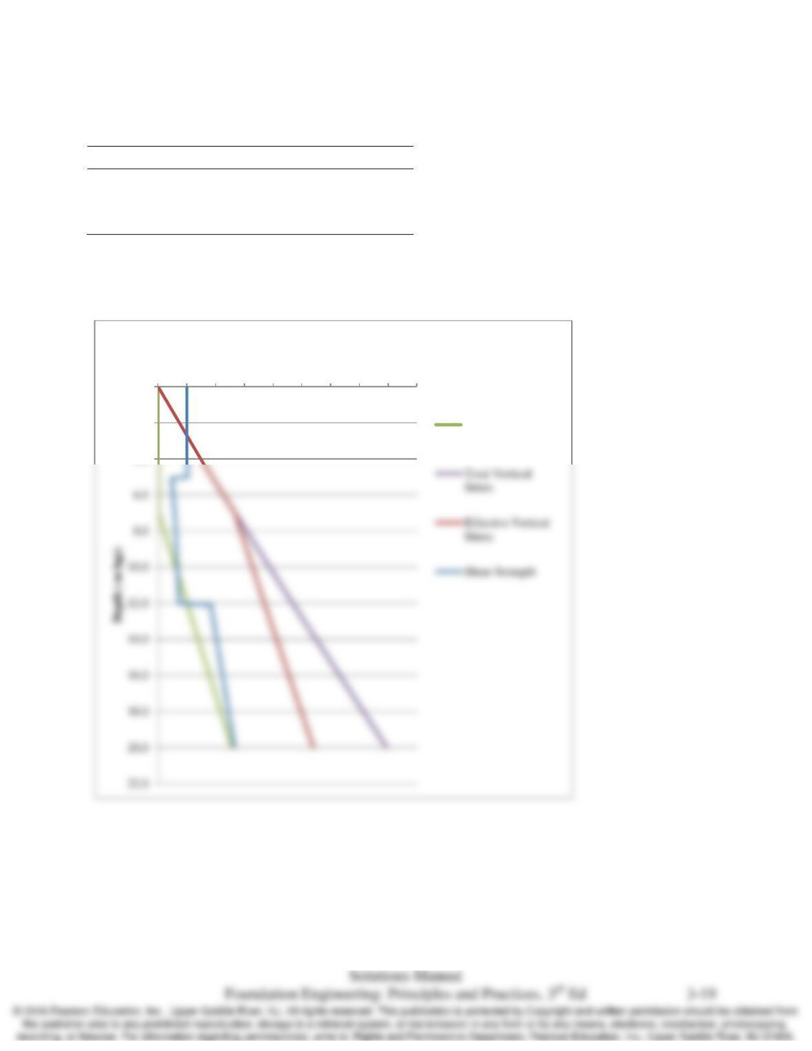
3.17 Repeat problem 3.16 using the following data:
The groundwater table is at a depth of 7 m.
Solution
0.0
2.0
4.0
0
50
100
150
200
250
300
350
400
450
kPa
Pore Water
Pressure
Depth (m)
γ
(kN/m3) cʹ (kPa)
ϕ
ʹ (degree) Su(kPa)
0-5 18.5 50
5-12 20.0 8.4 21
12–20 20.5 0 35

3.18 A 9 ft thick fill is to be placed on the soil shown in Figure 3.22. Once it is compacted this fill
will have a unit weight of 122 lb/ft3. Compute the ultimate consolidation settlement caused by
consolidation of the underlying clay.
Solution
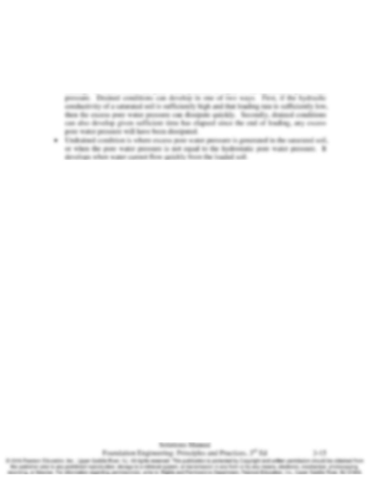
Using methods similar to those used to solve Problem 3.10 and Example 3.5, the following table
shows the results of the calculations.