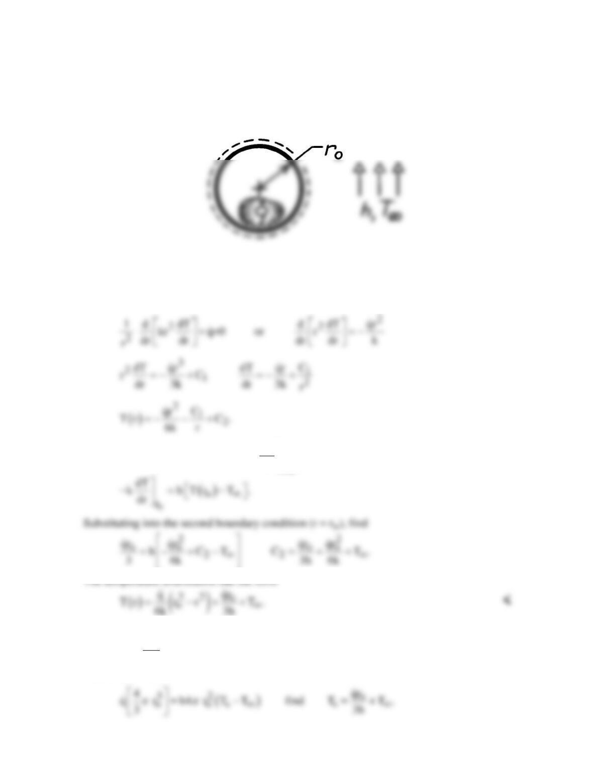
PROBLEM 3.84
KNOWN: Radius, thermal conductivity, heat generation and convection conditions
associated with a solid sphere.
FIND: Temperature distribution.
SCHEMATIC:
ASSUMPTIONS: (1) Steady-state conditions, (2) One-dimensional radial conduction, (3)
Constant properties, (4) Uniform heat generation.
ANALYSIS: Integrating the appropriate form of the heat diffusion equation,
The boundary conditions are:
1
r=0
dT 0 hence C 0, and
dr
= =
COMMENTS: To verify the above result, obtain T(ro) = Ts,
o
sqr
TT
3h ∞
= +
Applying energy balance to the control volume about the sphere,
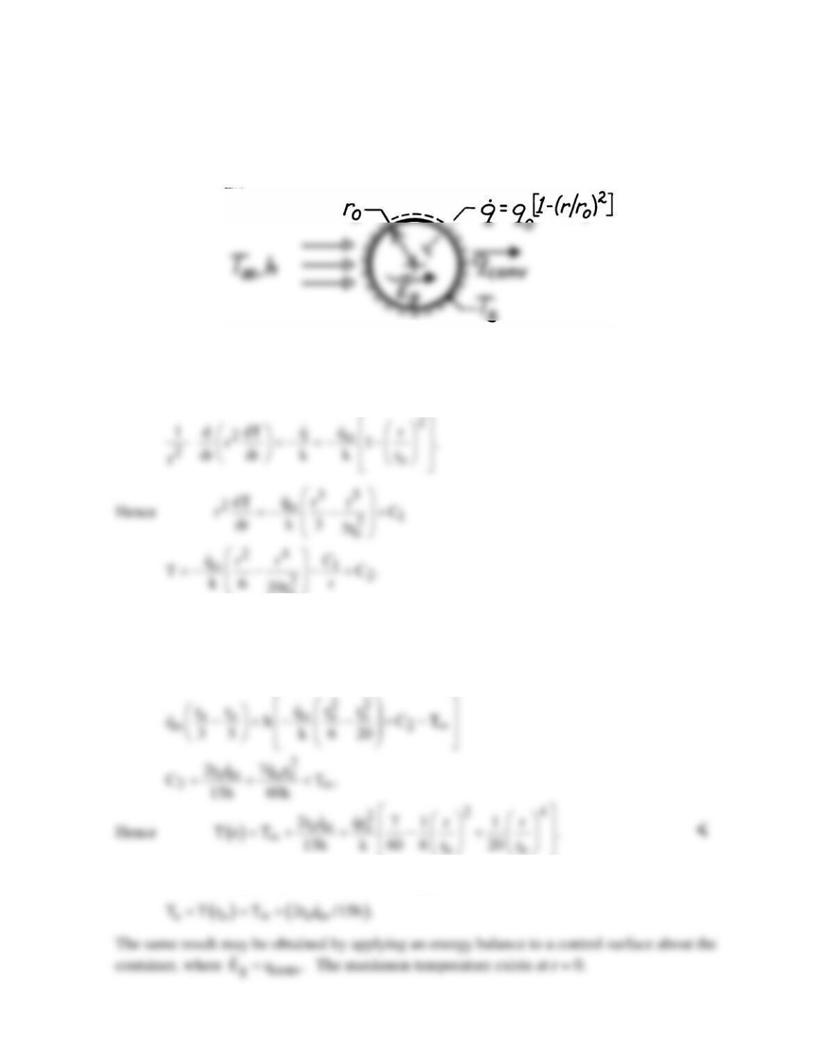
PROBLEM 3.85
KNOWN: Radial distribution of heat dissipation of a spherical container of radioactive
wastes. Surface convection conditions.
FIND: Radial temperature distribution.
SCHEMATIC:
ASSUMPTIONS: (1) Steady-state conditions, (2) One-dimensional conduction, (3) Constant
properties, (4) Negligible temperature drop across container wall.
ANALYSIS: The appropriate form of the heat equation is
o
From the boundary conditions,
( )
o
r=0 r=r o
dT/dr | 0 and kdT/dr | h T r T∞
=−=−
it follows that C1 = 0 and
COMMENTS: Applying the above result at ro yields
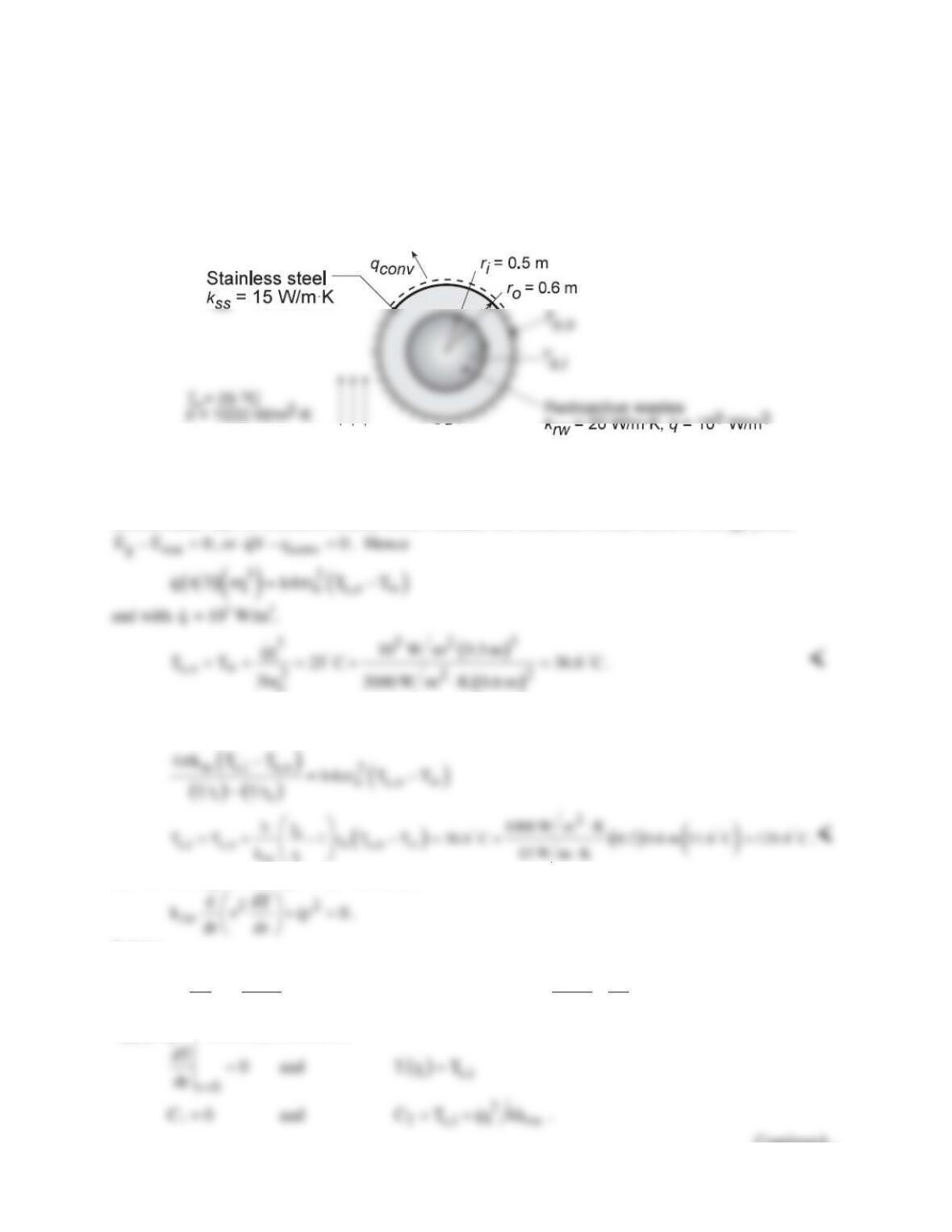
PROBLEM 3.86
KNOWN: Dimensions and thermal conductivity of a spherical container. Thermal conductivity and
volumetric energy generation within the container. Outer convection conditions.
FIND: (a) Outer surface temperature, (b) Container inner surface temperature, (c) Temperature
distribution within and center temperature of the wastes, (d) Feasibility of operating at twice the energy
generation rate.
SCHEMATIC:
ASSUMPTIONS: (1) Steady-state conditions, (2) Constant properties, (3) One-dimensional radial
conduction.
ANALYSIS: (a) For a control volume which includes the container, conservation of energy yields
(b) Performing a surface energy balance at the outer surface,
in out
EE 0−=
or
cond conv
qq0−=
.
Hence
ss i
(c) The heat equation in spherical coordinates is
Solving,
( )
32
21
12
rw rw
dT qr qr C
r C and T r C
dr 3k 6k r
=− + =− −+
Applying the boundary conditions,
Continued…
PROBLEM 3.86 (Cont.)
Hence
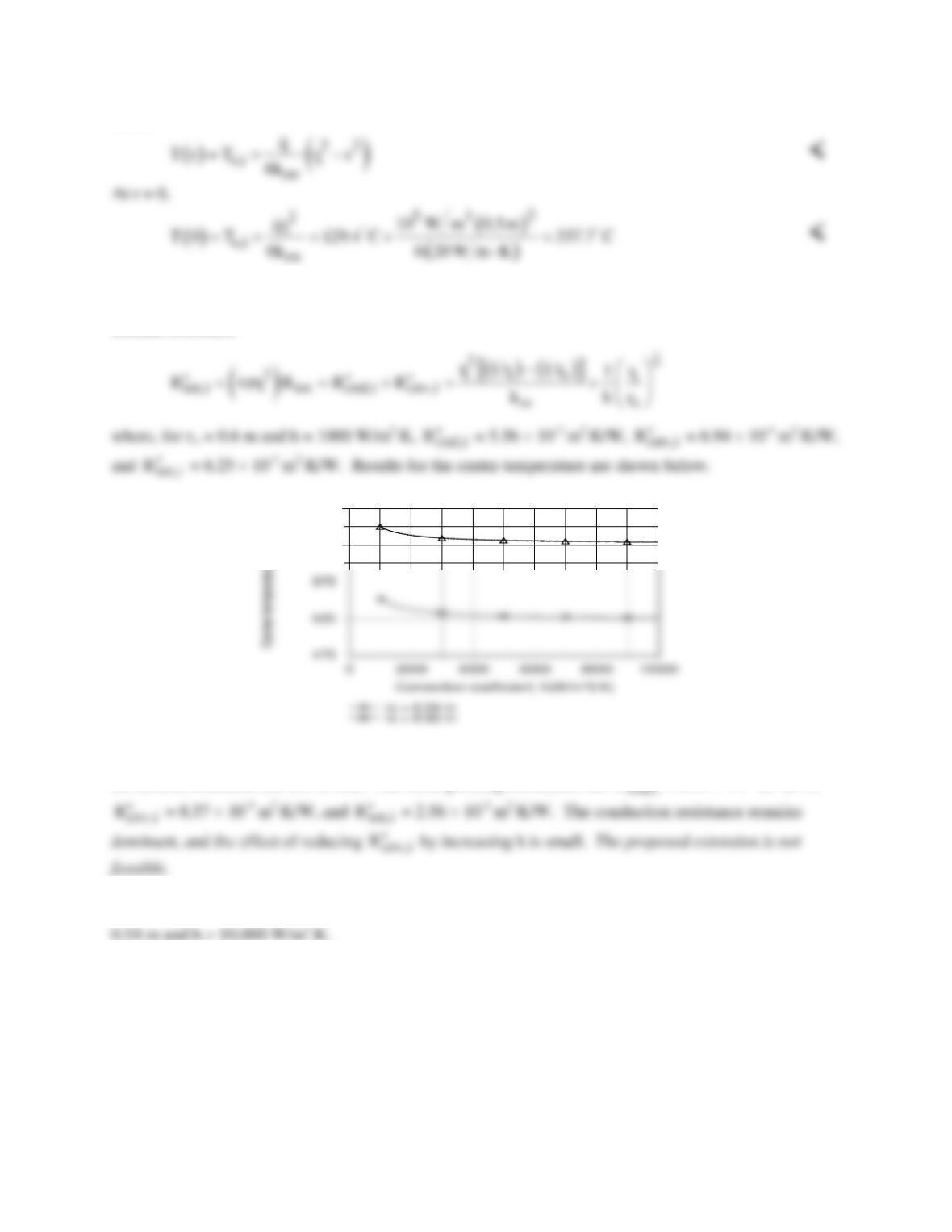
(d) The feasibility assessment may be performed by using the IHT model for one–dimensional, steady-
state conduction in a solid sphere, with the surface boundary condition prescribed in terms of the total
thermal resistance
625
675
Clearly, even with ro = 0.54 m = ro,min and h = 10,000 W/m2⋅K (a practical upper limit), T(0) > 475°C and
the desired condition can not be met. The corresponding resistances are
R′′
= 2.47 × 10⁻³ m2⋅K/W,
COMMENTS: A value of
q
= 1.79 × 10⁵ W/m3 would allow for operation at T(0) = 475°C with ro =
PROBLEM 3.87
KNOWN: Plane wall, long cylinder and sphere, each with characteristic length a, thermal
conductivity k and uniform volumetric energy generation rate
q.
FIND: (a) On the same graph, plot the dimensionless temperature, [
( ) ( )
T x or r T a−
]/[
q
a2/2k], vs.
the dimensionless characteristic length, x/a or r/a, for each shape; (b) Which shape has the smallest
temperature difference between the center and the surface? Explain this behavior by comparing the
ratio of the volume-to–surface area; and (c) Which shape would be preferred for use as a nuclear fuel
element? Explain why?
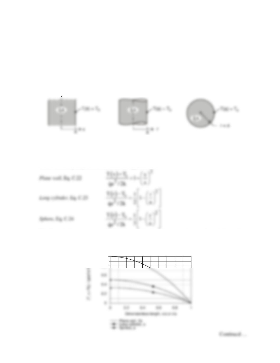
SCHEMATIC:
Plane wall Long cylinder Sphere
ASSUMPTIONS: (1) Steady-state conditions, (2) One-dimensional conduction, (3) Constant
properties and (4) Uniform volumetric generation.
ANALYSIS: (a) For each of the shapes, with T(a) = Ts, the dimensionless temperature distributions
can be written by inspection from results in Appendix C.3.
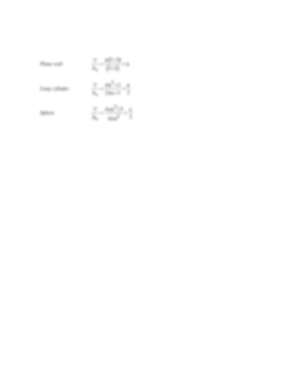
The dimensionless temperature distributions using the foregoing expressions are shown in the graph
below.
Dimensionless temperature distribution
0.8
1
PROBLEM 3.87 (Cont.)
(b) The sphere shape has the smallest temperature difference between the center and surface, T(0) –
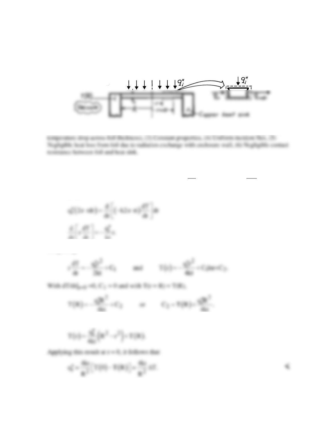
T(a). The ratio of volume-to–surface–area, ∀/As, for each of the shapes is
The smaller the ∀/As ratio, the smaller the temperature difference, T(0) – T(a).
(c) The sphere would be the preferred element shape since, for a given ∀/As ratio, which controls the
generation and transfer rates, the sphere will operate at the lowest temperature.
PROBLEM 3.88
KNOWN: Radius, thickness, and incident flux for a radiation heat gauge.
FIND: Expression relating incident flux to temperature difference between center and edge of
gauge.
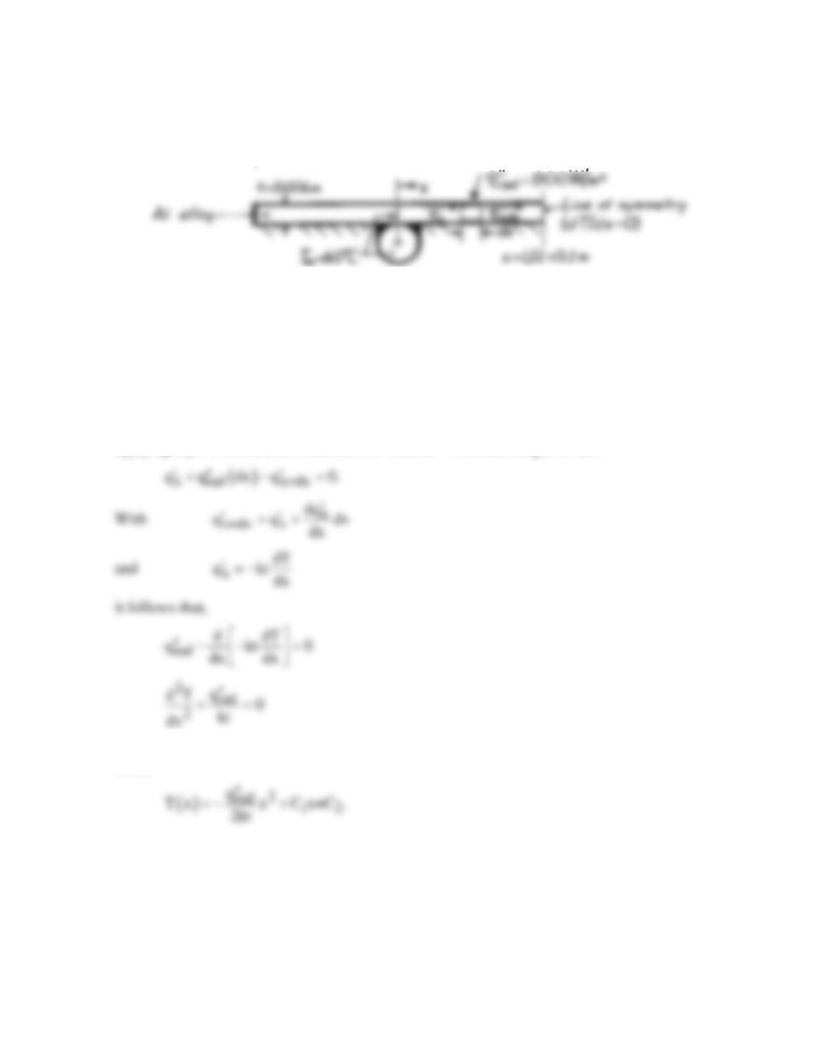
SCHEMATIC:
ASSUMPTIONS: (1) Steady-state conditions, (2) One-dimensional conduction in r (negligible
ANALYSIS: Applying energy conservation to a circular ring extending from r to r + dr,
( ) ( )
r
r i r+dr r r+dr r
dT dq
q q 2 rdr q , q k 2 rt , q q dr.
dr dr
ππ
′′
+= =− =+
Rearranging, find that
dr dr kt
Integrating,
Hence, the temperature distribution is
COMMENTS: This technique allows for determination of a radiation flux from
measurement of a temperature difference. It becomes inaccurate if emission from the foil
becomes significant.
PROBLEM 3.89
KNOWN: Net radiative flux to absorber plate.
FIND: (a) Maximum absorber plate temperature, (b) Rate of energy collected per tube.
SCHEMATIC:
ASSUMPTIONS: (1) Steady-state conditions, (2) One-dimensional (x) conduction along
absorber plate, (3) Uniform radiation absorption at plate surface, (4) Negligible losses by
conduction through insulation, (5) Negligible losses by convection at absorber plate surface,
(6) Temperature of absorber plate at x = 0 is approximately that of the water.
PROPERTIES: Table A-1, Aluminum alloy (2024-T6): k ≈ 180 W/m⋅K.
ANALYSIS: The absorber plate acts as an extended surface (a conduction–radiation system),
and a differential equation which governs its temperature distribution may be obtained by
applying Eq.1.11b to a differential control volume. For a unit length of tube
Integrating twice it follows that, the general solution for the temperature distribution has the
form,
Continued …
PROBLEM 3.89 (Cont.)
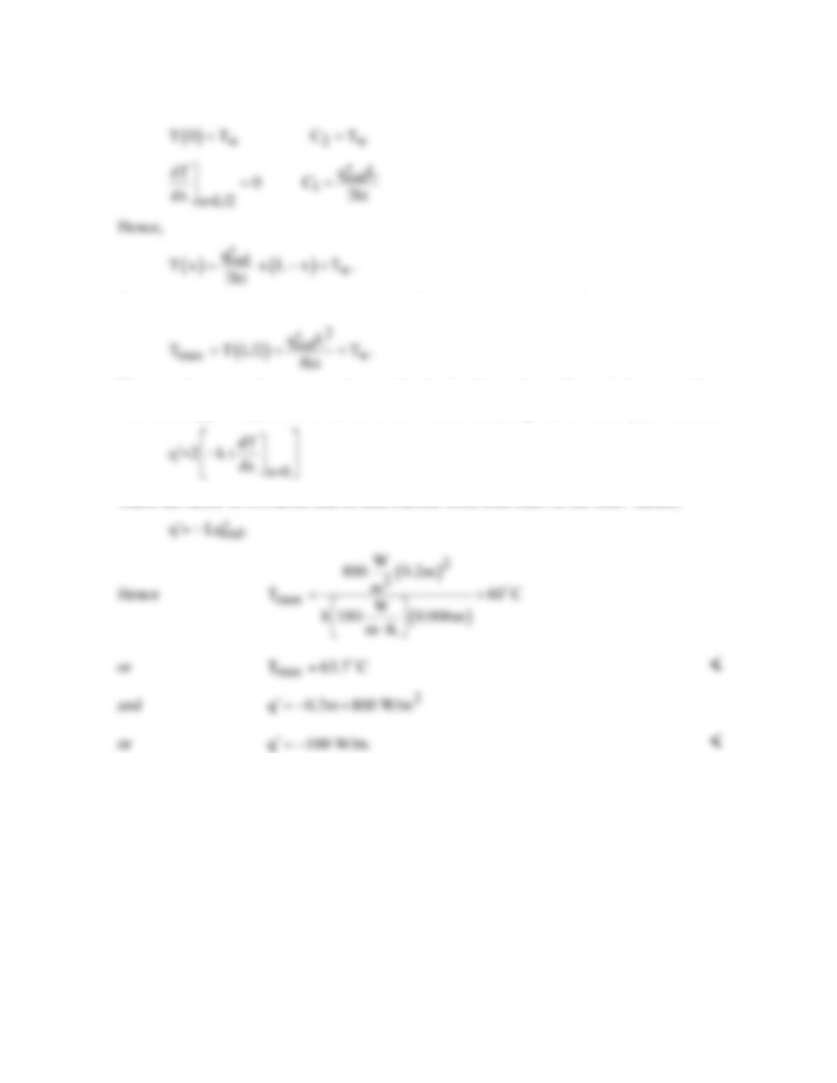
The boundary conditions are:
The maximum absorber plate temperature, which is at x = L/2, is therefore
The rate of energy collection per tube may be obtained by applying Fourier’s law at x = 0.
That is, energy is transferred to the tubes via conduction through the absorber plate. Hence,
where the factor of two arises due to heat transfer from both sides of the tube. Hence,
COMMENTS: Convection losses in the typical flat plate collector, which is not evacuated,
would reduce the value of
′
q .
PROBLEM 3.90
KNOWN: Diameter and base temperature of a silicon carbide nanowire, required temperature of
the catalyst tip.
FIND: Maximum length of a nanowire that may be grown under specified conditions.
ASSUMPTIONS: (1) Nanowire stops growing when Tc = T(x = L) = 3000 K, (2) Constant
properties, (3) One-dimensional heat transfer, (4) Convection from the tip of the nanowire, (5)
Nanowire grows very slowly, (6) Negligible impact of nanoscale heat transfer effects.
PROPERTIES: Table A.2, silicon carbide (1500 K): k = 30 W/m⋅K.
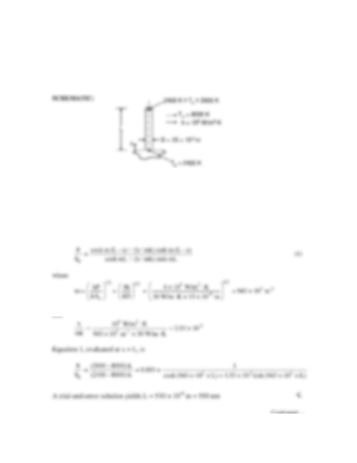
ANALYSIS: The tip of the nanowire is initially at T = 2400 K, and increases in temperature as
the nanowire becomes longer. At steady–state, the tip reaches T = 3000 K. The temperature
distribution at steady-state is given by Eq. 3.75:
Continued…

PROBLEM 3.90 (Cont.)
COMMENTS: (1) The importance of radiation heat transfer may be ascertained by evaluating
Eq. 1.9. Assuming large surroundings at a temperature of Tsur = 8000 K and an emissivity of
unity, the radiation heat transfer coefficient at the fin tip is
PROBLEM 3.91
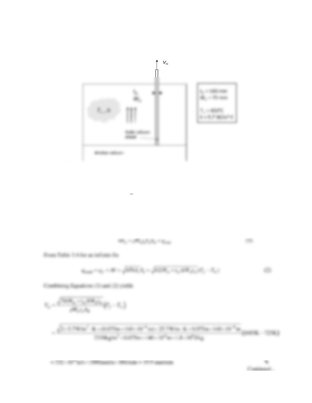
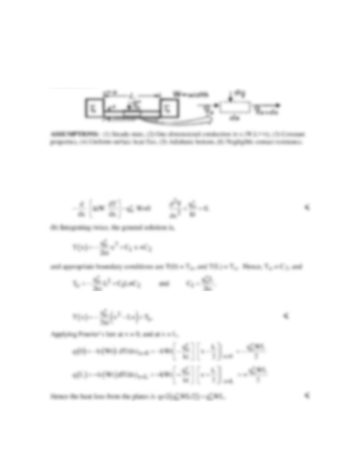
KNOWN: Process for growing thin, photovoltaic grade silicon sheets. Sheet dimensions, ambient
temperature and heat transfer coefficient.
FIND: The velocity at which the silicon sheet can be extracted from the pool of molten silicon.
SCHEMATIC:
ASSUMPTIONS: (1) Steady–state, one-dimensional conditions, (2) Negligible radiation heat
transfer, (3) Silicon sheet behaves as an infinite fin, (4) Constant properties, (5) Neglect advection
inside the silicon sheet, (6) Neglect the presence of the strings, (7) Molten silicon is isothermal at the
melting point (1685 K).
PROPERTIES: Table A-1, Silicon (
T
= (1685 K + 723 K)/2 = 1204 K
≈
1200 K): k = 25.7
W/m⋅K,
ρ
= 2330 kg/m3, hsl = 1.8 × 10⁶ J/kg (given).
ANALYSIS: The velocity is expected to be very small. Therefore, heat transfer within the silicon
sheet may be considered to be by conduction only. In addition, thermal energy is generated due to
solidification at the solid-liquid interface, and must be removed by conduction along the silicon sheet.
Therefore,
PROBLEM 3.91 (Cont.)
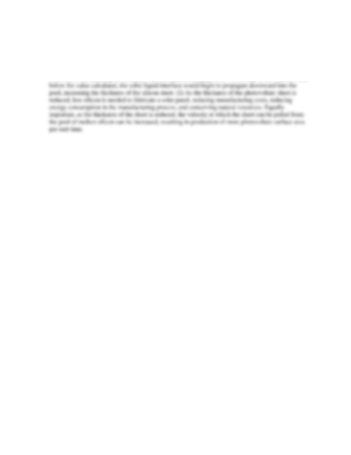
COMMENTS: (1) The rate at which the photovoltaic sheet can be manufactured is limited by heat
transfer effects. If the velocity were increased above the value calculated, the solid sheet would be
lifted out of the molten pool of silicon, and the manufacturing process would stop. If the velocity were
PROBLEM 3.92
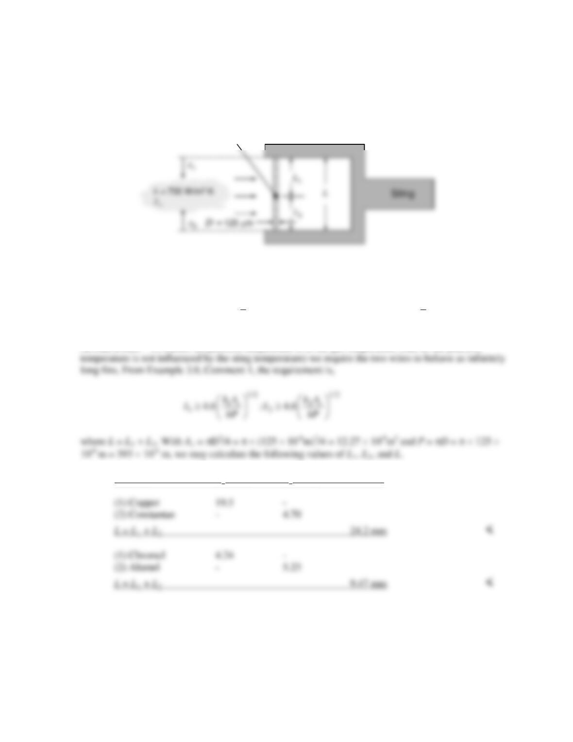
KNOWN: Dimensions of a plate insulated on its bottom and thermally joined to heat sinks at its
ends. Net heat flux at top surface.
FIND: (a) Differential equation which determines temperature distribution in plate, (b) Temperature
distribution and heat loss to heat sinks.
SCHEMATIC:
ANALYSIS: (a) Applying conservation of energy to the differential control volume, qx + dq
= qx +dx, where qx+dx = qx + (dqx/dx) dx and
( )
o
dq=q W dx .
′′ ⋅
Hence,
( )
xo
dq / dx q W=0.
′′
−
From Fourier’s law,
( )
x
q k t W dT/dx.=−⋅
Hence, the differential
equation for the temperature distribution is
Hence, the temperature distribution is
COMMENTS: (1) Note signs associated with q(0) and q(L). (2) Note symmetry about x =
L/2. Alternative boundary conditions are T(0) = To and dT/dx)x=L/2=0.
PROBLEM 3.93
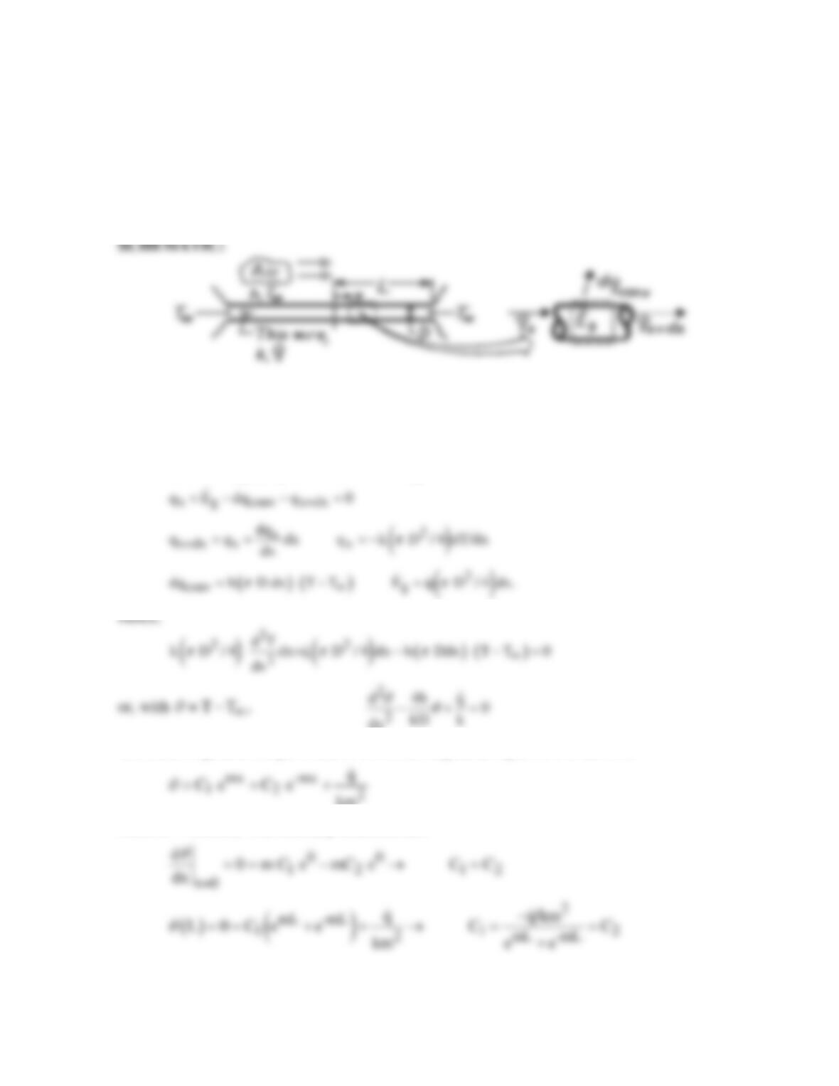
KNOWN: Wire diameters associated with a thermocouple junction, value of the convection heat
transfer coefficient.
FIND: Minimum wire lengths necessary to ensure the junction temperature is at the gas temperature.
SCHEMATIC:
ASSUMPTIONS: (1) Steady–state, one-dimensional conditions, (2) Negligible radiation heat
transfer, (3) Constant properties, (4) Infinitely long fin behavior.
PROPERTIES: Table A-1, Copper (
T
= 300 K): k = 401 W/m⋅K; Constantan (
T
= 300 K): k = 23
W/m⋅K; Given, Chromel: k = 19 W/m⋅K; Alumel: k = 29 W/m⋅K.
ANALYSIS: To ensure the junction temperature is at the gas temperature (that is, the junction
Material L1 (mm) L2 (mm)
COMMENTS: Use of the chromel–alumel thermocouple junction leads to a substantial reduction in
the size of the measurement device, while simultaneously minimizing measurement error associated
with conduction along the wires to or from the sting.
Thermocouple junction
PROBLEM 3.94
KNOWN: Thermal conductivity, diameter and length of a wire which is annealed by passing an
electrical current through the wire.
FIND: (a) Steady–state temperature distribution along wire, (b) Maximum wire temperature, (c)
Average wire temperature.
ASSUMPTIONS: (1) Steady-state conditions, (2) One-dimensional conduction along the wire, (3)
Constant properties, (4) Negligible radiation, (5) Uniform convection coefficient h.
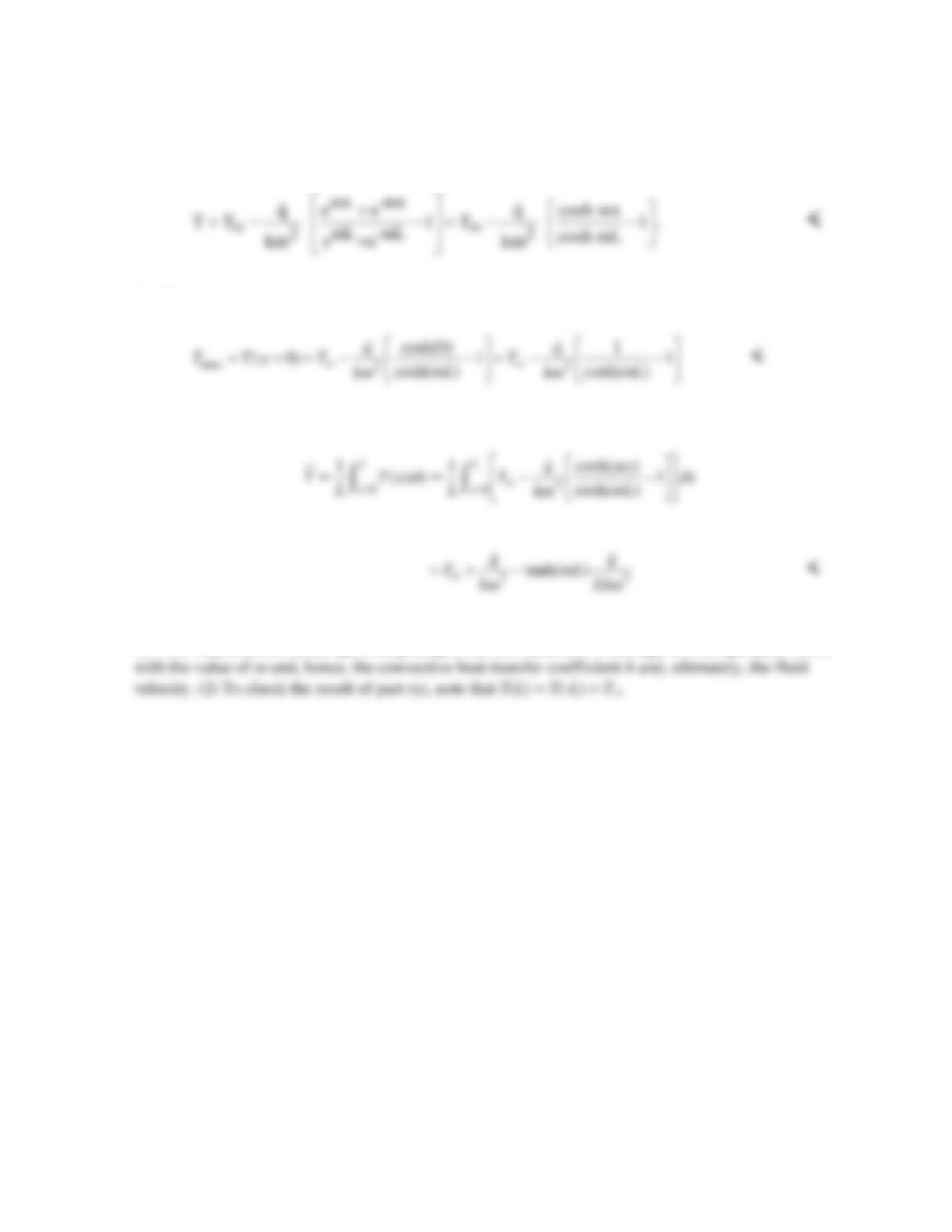
ANALYSIS: (a) Applying conservation of energy to a differential control volume,
dx
The solution (general and particular) to this nonhomogeneous equation is of the form
km
where m2 = (4h/kD). The boundary conditions are:
Continued…
PROBLEM 3.94 (Cont.)
The temperature distribution has the form
(b) The maximum wire temperature exists at x = 0. Hence,
(c) The average wire temperature may be obtained by evaluating the expression
COMMENTS: (1) This process is commonly used to anneal wire and spring products. It is also used
for flow measurement based upon the principle that the maximum or average wire temperature varies
PROBLEM 3.95
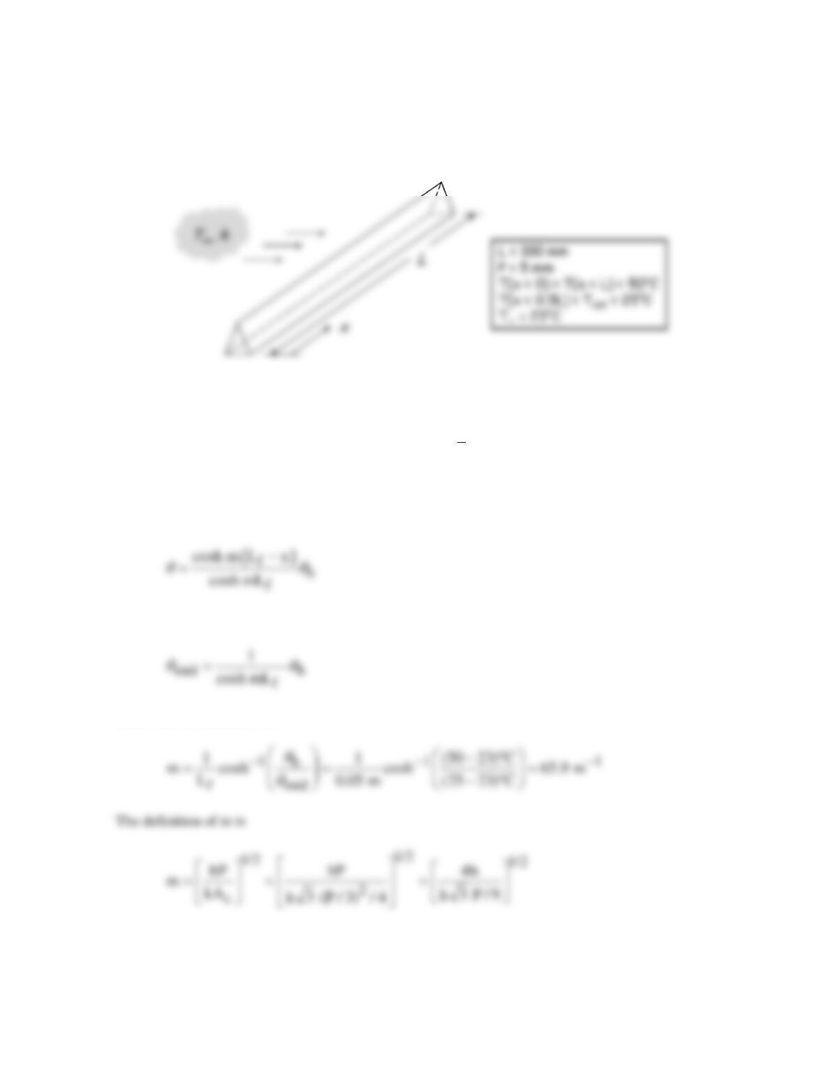
KNOWN: Dimensions of stainless steel rod of triangular cross section. Base and midpoint
temperatures. Environment temperature.
FIND: Heat transfer coefficient and rate of heat loss from rod.
SCHEMATIC:
ASSUMPTIONS: (1) Steady-state conditions, (2) Temperature is nearly uniform over the cross
section, (3) Constant properties, (4) Negligible radiation, (5) Uniform convection coefficient h, (6)
Cross–section is an equilateral triangle.
PROPERTIES: Table A-1, Stainless steel (AISI 304),
( )
T 310 K : k 15.1 W/m K.= = ⋅
ANALYSIS: Due to symmetry, the plane at x = L/2 has zero heat flux, that is, it is adiabatic.
Therefore, the rod can be treated as two fins of length Lf = L/2 with adiabatic tips. The temperature
distribution is therefore (Equation 3.80):
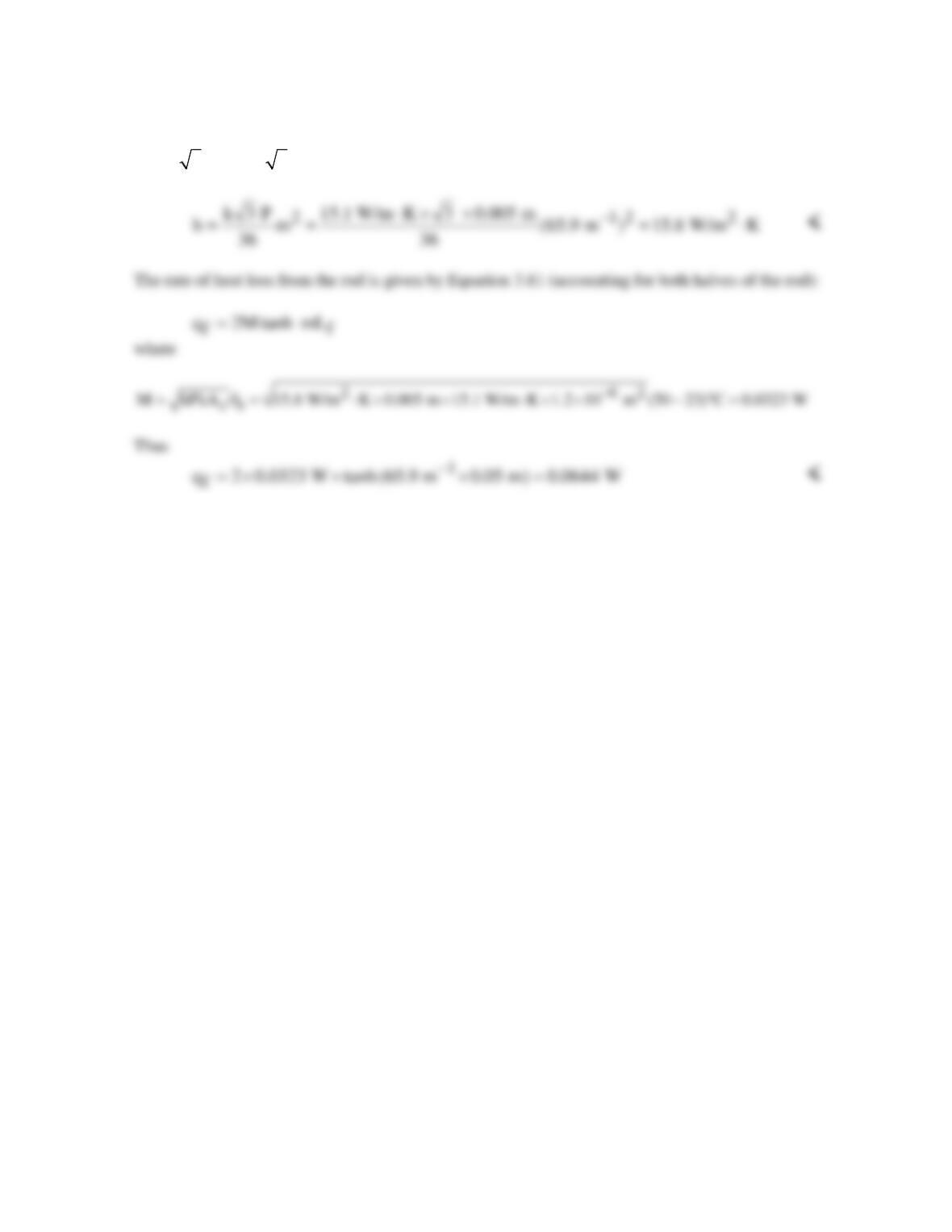
Evaluating this at the midpoint, x = Lf, we can write:
which can be solved for m:
Continued…
PROBLEM 3.95 (Cont.)
where the area of an equilateral triangle is related to the length of a side, s, according to
2 2 62
c
A 3 s / 4 3 (P / 3) / 4 1.2 10 m .
−
= = = ×
Now the heat transfer coefficient can be found:
COMMENTS: Is this an accurate way to find the heat transfer coefficient? If the midpoint
temperature were measured as 24.5°C instead of 25°C, the heat transfer coefficient would come out to
be 18.7 W/m2⋅K, an 18% error. Depending on the application, this might or might not be an
acceptable level of error.
PROBLEM 3.96
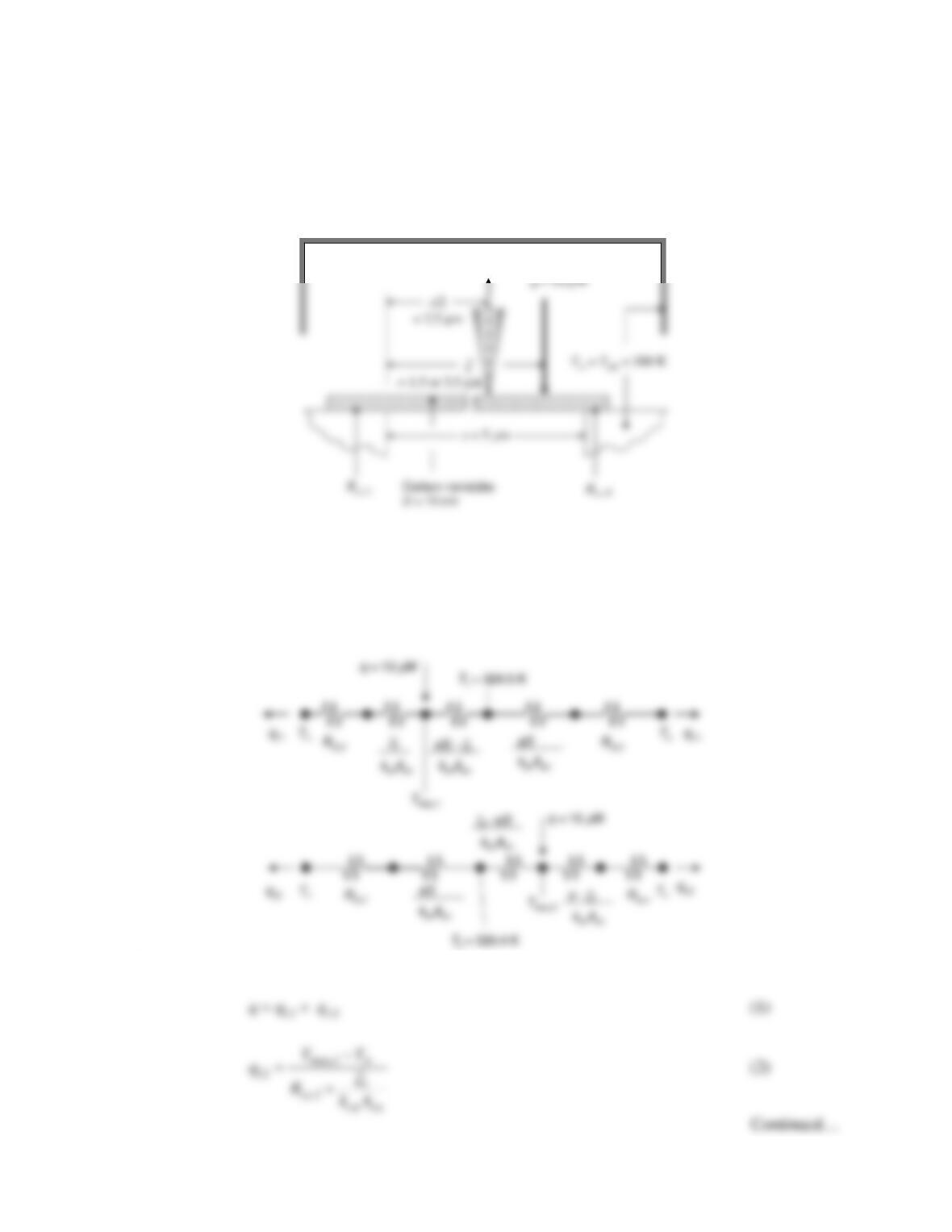
KNOWN: Trench length and nanotube diameter. Laser irradiation of known power at two distinct
axial locations. Measured nanotube temperatures at the trench half-width. Nanotube thermal
conductivity. Island temperature.
FIND: Thermal contact resistances at the left and right ends of the nanotube.
SCHEMATIC:
Laser irradiationTemperature measurement
ASSUMPTIONS: (1) Steady–state, one-dimensional conduction. (2) Constant properties. (3)
Negligible radiation and convection losses.
ANALYSIS: Thermal circuits may be drawn for the two laser irradiation locations as follows. The
top circuit corresponds to irradiation on the left half of the nanotube. The bottom circuit corresponds
to irradiation of the right half of the nanotube.
The following equations may be written for irradiation of the left side of the nanotube (top circuit).