PROBLEM 3.110 (Cont.)
The new UP replaces the old hP in the fin heat transfer analysis, therefore the new heat
transfer rate is given by
The fin heat transfer rate is maximized when UP is maximized, therefore the optimum value
of r2 can be found from setting the derivative of UP with respect to r2 to zero:
Therefore the optimum paint thickness is 1.5 mm. <
The heat transfer rate with the optimum paint thickness can now be determined.
COMMENTS: (1) The modest increase in the heat transfer rate would probably not justify the
effort of applying a relatively thick layer of paint to the fins. (2) The existence of an optimum
paint thickness is due to the competing effects of increased surface area (increases heat transfer)
and increased thermal resistance (decreases heat transfer). This scenario is identical to the critical
insulation thickness for a cylinder and the optimum radius is the same as in that case.
PROBLEM 3.111
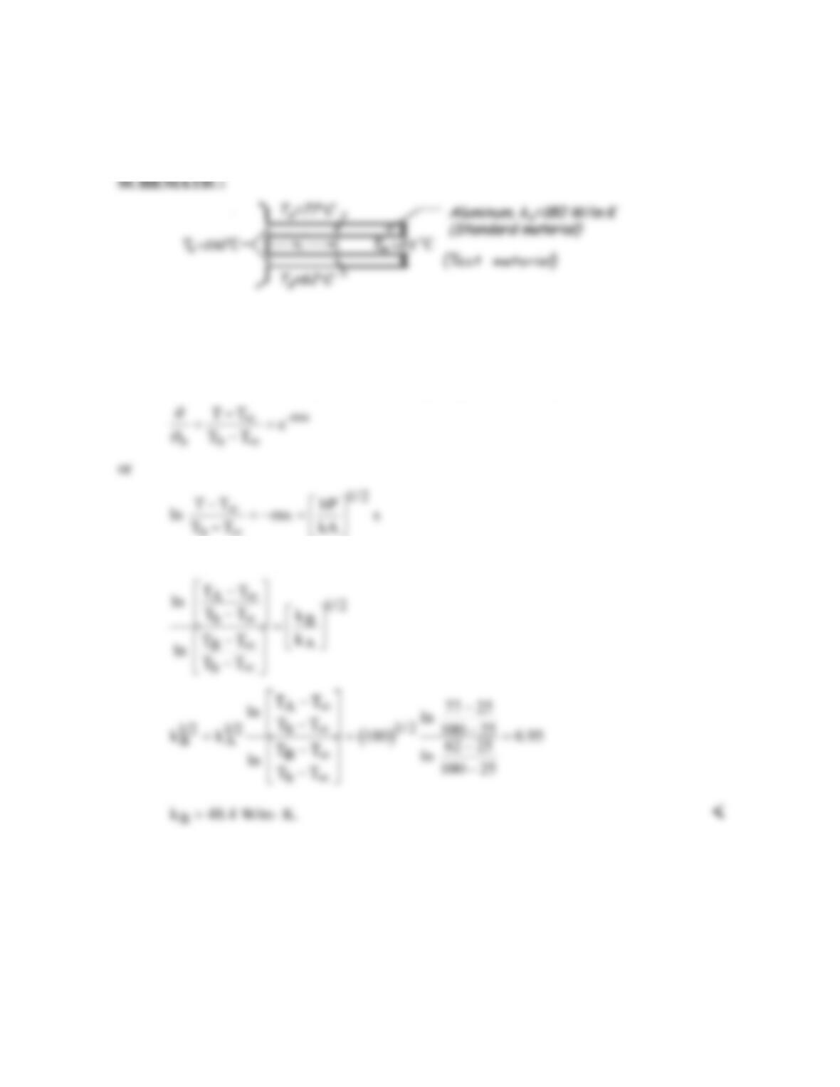
KNOWN: Base temperature, ambient fluid conditions, and temperatures at a prescribed
distance from the base for two long rods, with one of known thermal conductivity.
FIND: Thermal conductivity of other rod.
ASSUMPTIONS: (1) Steady–state, (2) One-dimensional conduction along rods, (3) Constant
properties, (4) Negligible radiation, (5) Negligible contact resistance at base, (6) Infinitely
long rods, (7) Rods are identical except for their thermal conductivity.
ANALYSIS: With the assumption of infinitely long rods, the temperature distribution is
b
∞
Hence, for the two rods,
COMMENTS: Providing conditions for the two rods may be maintained nearly identical, the
above method provides a convenient means of measuring the thermal conductivity of solids.
PROBLEM 3.112
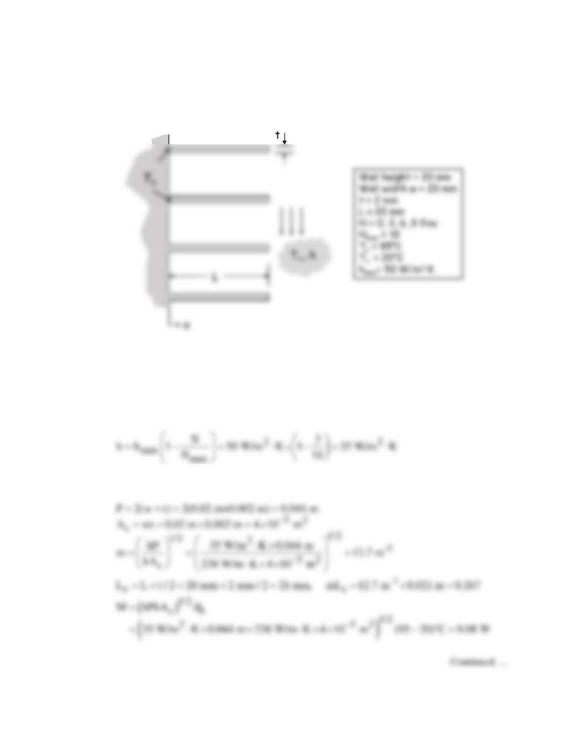
KNOWN: Array of aluminum fins with specified dimensions. Base and environment temperatures.
Dependence of heat transfer coefficient on number of fins.
FIND: Total rate of heat transfer for 0, 3, 6, and 9 fins.
SCHEMATIC:
ASSUMPTIONS: (1) Steady-state conditions, (2) Temperature nearly uniform across fin cross
section, (3) Constant properties, (4) Negligible radiation, (5) Uniform h.
PROPERTIES: Table A.1, Aluminum (pure), T ≅ 330 K: k ≅ 238 W/m⋅K.
ANALYSIS: Equations 3.103 and 3.107 can be used to calculate the heat transfer rate from a fin
array. The calculations are performed here for N = 3 fins. The heat transfer coefficient is:
Then
PROBLEM 3.112 (Cont.)
The heat transfer rate for a single fin is
3 2.37 W 35 W/m K 0.00028 m (95 20) C 7.84 W
=× + ⋅× × − °=
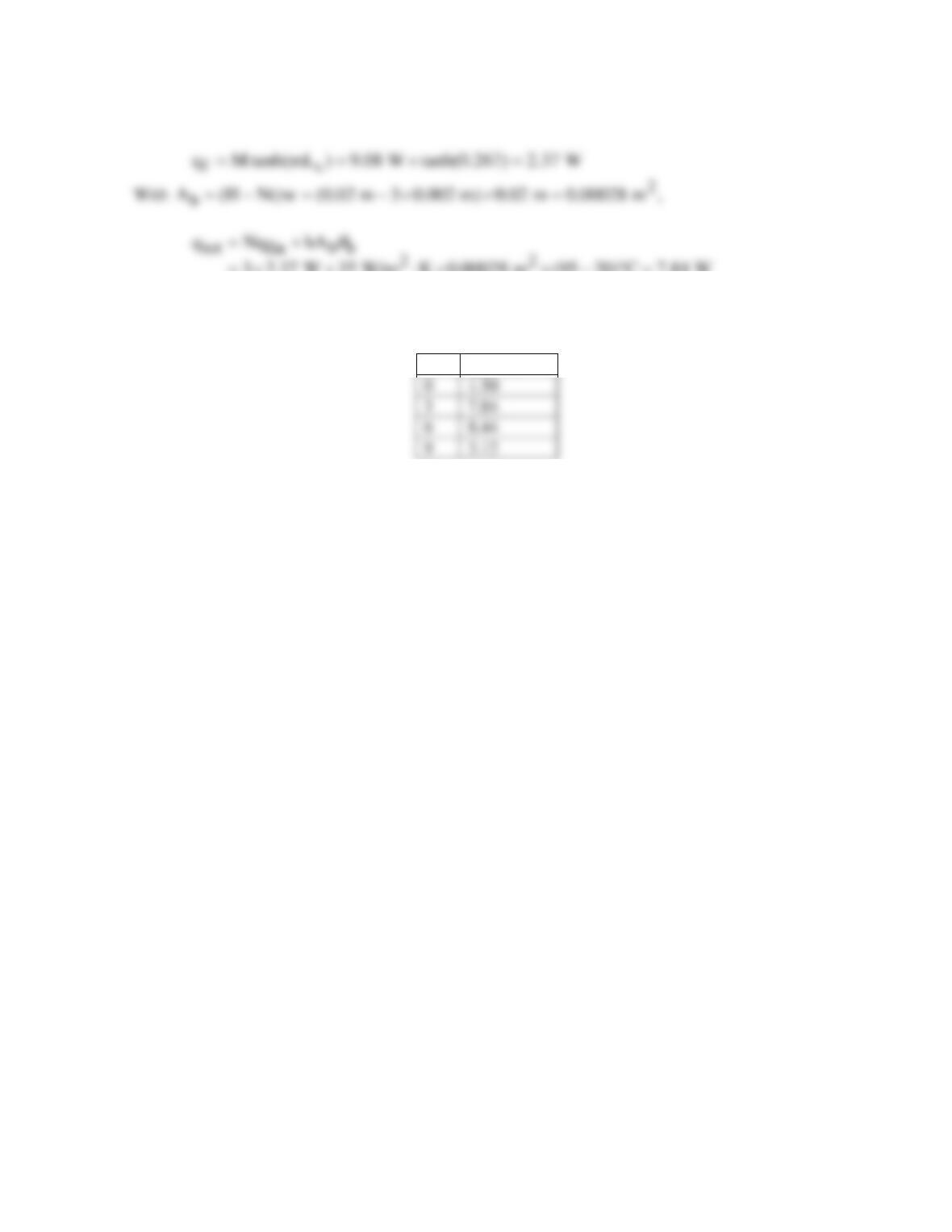
Repeating the calculations for different numbers of fins, the results are given in the table below. <
N
qtot (W)
0
1.50
3
7.84
6
8.44
9
3.12
COMMENTS: There is a trade–off between increasing the number of fins and decreasing the heat
transfer coefficient because of blockage. In the case considered, the maximum heat transfer rate is for
N = 5 fins and is qtot = 8.89 W.
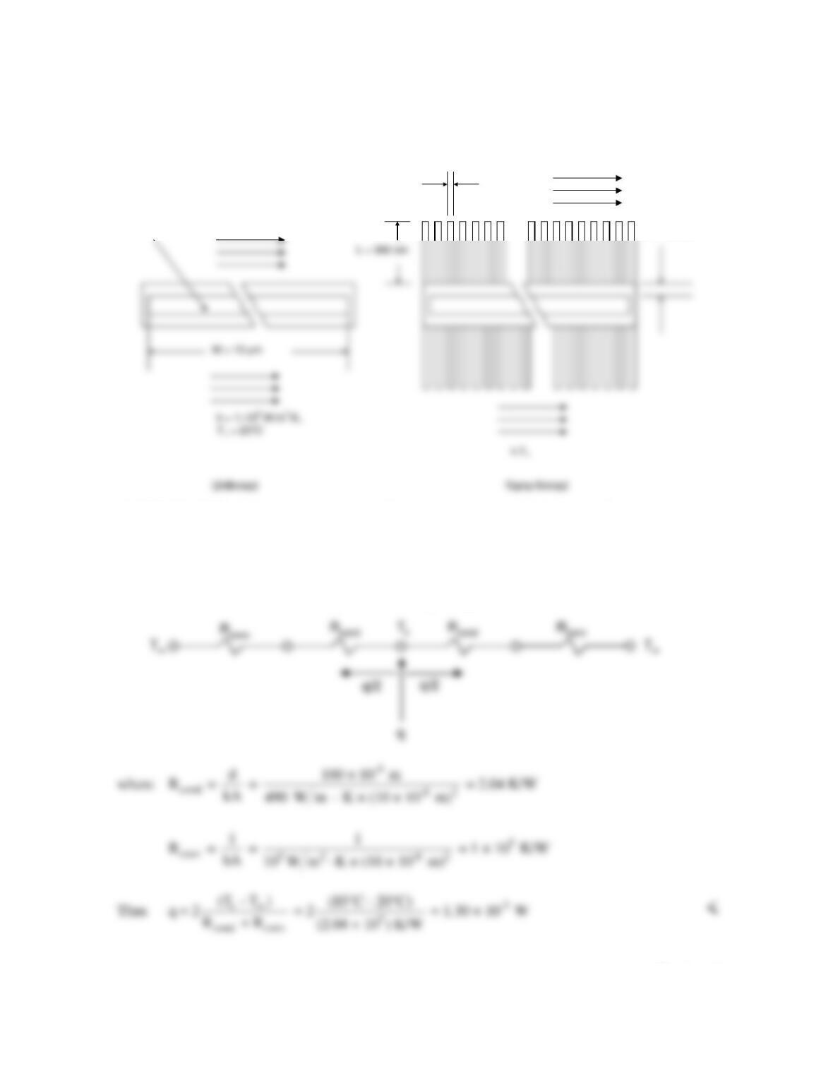
PROBLEM 3.113
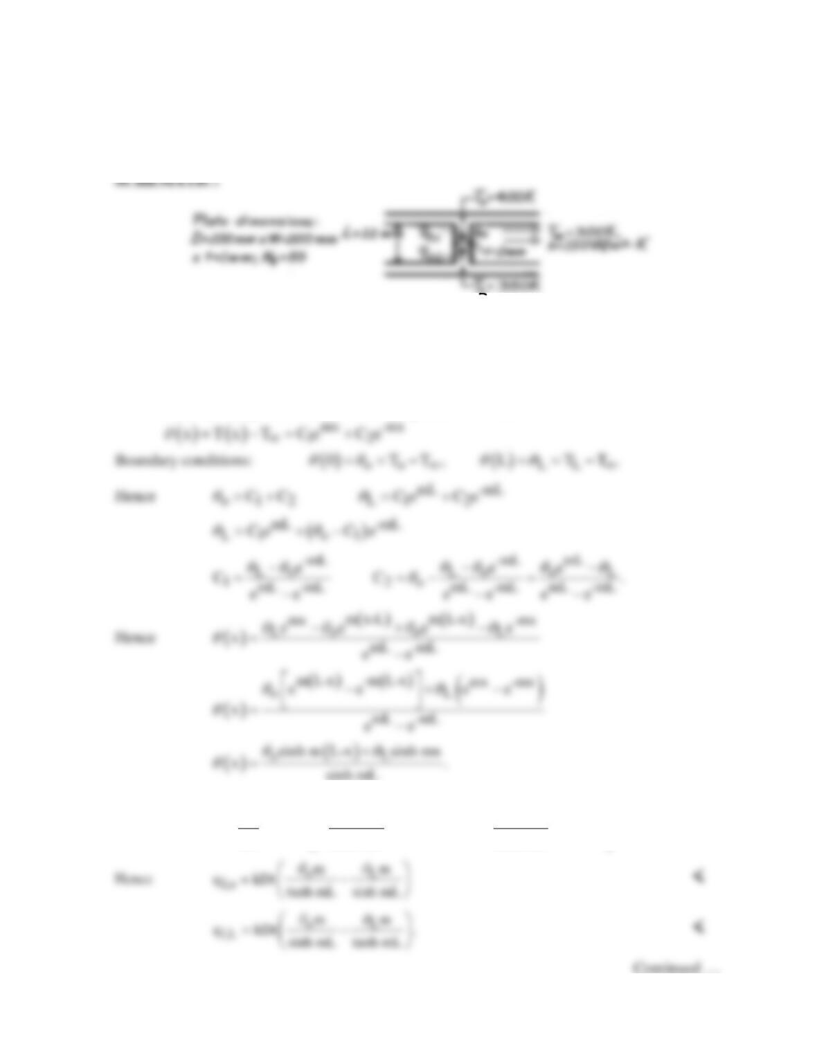
KNOWN: Arrangement of fins between parallel plates. Temperature and convection coefficient of
air flow in finned passages. Maximum allowable plate temperatures.
FIND: (a) Expressions relating fin heat transfer rates to end temperatures, (b) Maximum power
dissipation for each plate.
ASSUMPTIONS: (1) Steady-state conditions, (2) One-dimensional conduction in fins, (3) Constant
properties, (4) Negligible radiation, (5) Uniform h, (6) Negligible variation in T∞, (7) Negligible
contact resistance.
PROPERTIES: Table A.1, Aluminum (pure), 375 K: k = 240 W/m⋅K.
ANALYSIS: (a) The general solution for the temperature distribution in a fin is
sinh mL
The fin heat transfer rate is then
( )
oL
fc
m
dT m
q kA kDt cosh m L x cosh mx .
dx sinh mL sinh mL
qq
=− =− − −+
PROBLEM 3.113 (Cont.)
(b)
( )
1/ 2
1/ 2 2-1
c
150 W/m K 2 0.1 m+2 0.001 m
hP
m= 35.5 m
kA 240 W/m K 0.1 m 0.001 m
⋅× ×
= =
⋅× ×
Maximum power dissipations are therefore
( )
o,max f f,o f o
q N q W N t Dh
q
= +−
L,max
COMMENTS: (1) It is of interest to determine the air velocity needed to prevent excessive heating of the air as
it passes between the plates. If the air temperature change is restricted to ∆T∞ = 5 K, its flowrate must be
(2) A negative value of qL,max implies that the bottom plate must be cooled externally to
maintain the plate at 350 K.
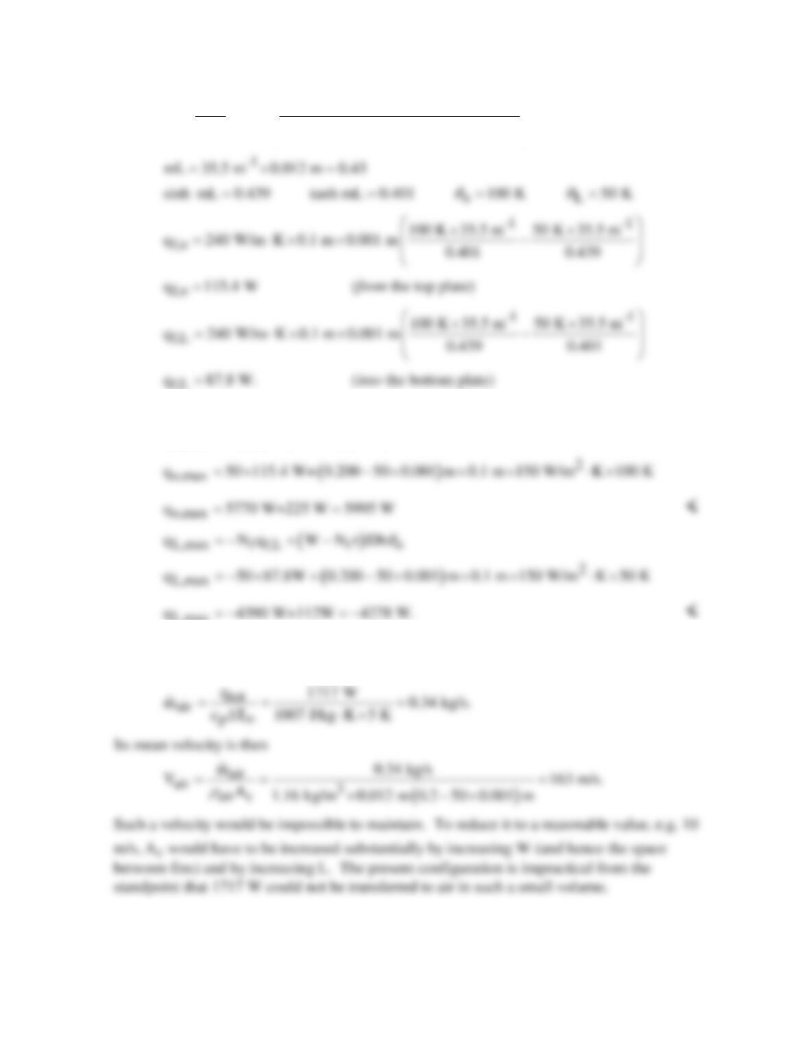
PROBLEM 3.114
KNOWN: Dimensions and maximum allowable temperature of an electronic chip. Thermal contact
resistance between chip and heat sink. Dimensions and thermal conductivity of heat sink.
Temperature and convection coefficient associated with air flow through the heat sink.
FIND: (a) Maximum allowable chip power for heat sink with prescribed number of fins, fin
thickness, and fin pitch, and (b) Effect of fin thickness/number and convection coefficient on
performance.
SCHEMATIC:
ASSUMPTIONS: (1) Steady-state, (2) One-dimensional heat transfer, (3) Isothermal chip, (4)
Negligible heat transfer from top surface of chip, (5) Negligible temperature rise for air flow, (6)
Uniform convection coefficient associated with air flow through channels and over outer surfaces of
heat sink, (7) Negligible radiation.
ANALYSIS: (a) From the thermal circuit,
(b) The following results are obtained from parametric calculations performed to explore the effect of
decreasing the number of fins and increasing the fin thickness.
Continued …
W = 20 mm
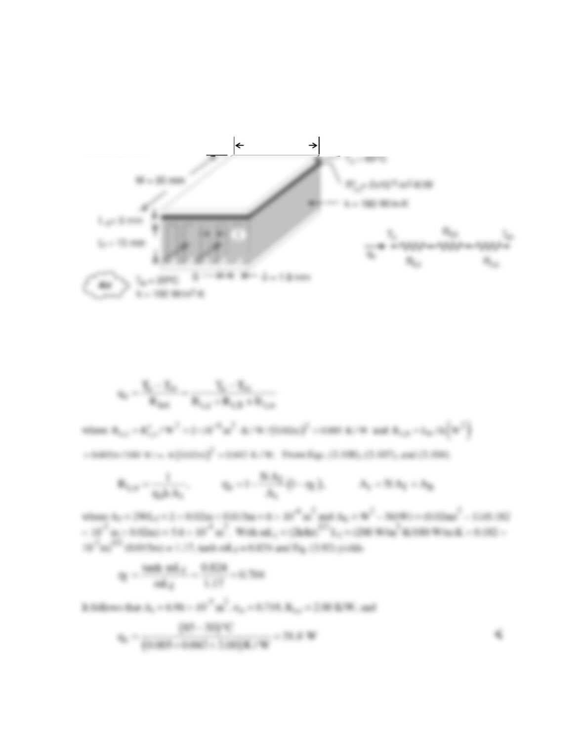
PROBLEM 3.114 (Cont.)
N t(mm) hf Rt,o (K/W) qc (W) At (m2)
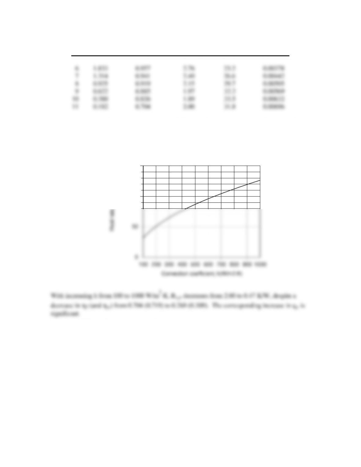
Although hf (and ho) increases with decreasing N (increasing t), there is a reduction in At which
yields a minimum in Rt,o, and hence a maximum value of qc, for N = 10. For N = 11, the effect of h
on the performance of the heat sink is shown below.
COMMENTS: (1) The heat sink significantly increases the allowable heat dissipation. If it were not
used and heat was simply transferred by convection from the surface of the chip with h = 100
W/m2⋅K, Rtot = 2.05 K/W from Part (a) would be replaced by Rcnv = 1/hW2 = 25 K/W, yielding qc =
2.60 W. (2) The air temperature will increase as it flows through the heat sink. Therefore the required
air velocity will be greater than determined here. See Problem 11.68.
Heat rate as a function of convection coefficient (N=11)
100
150
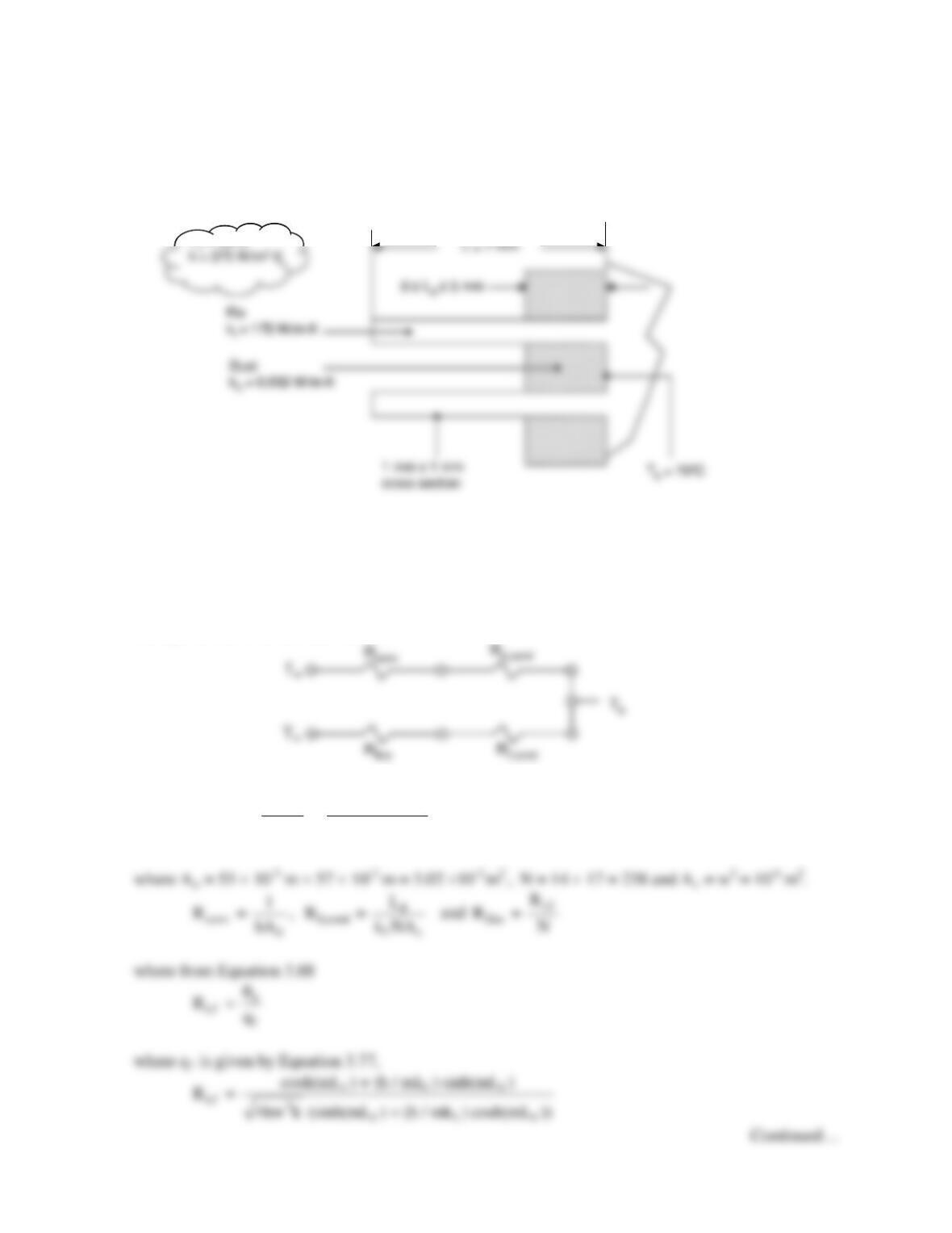
PROBLEM 3.115
KNOWN: Dimensions of electronics package and finned nano–heat sink. Temperature and heat
transfer coefficient of coolant.
FIND: Maximum heat rate to maintain temperature below 85°C for finned and un-finned packages.
SCHEMATIC:
ASSUMPTIONS: (1) Steady-state, (2) Negligible temperature variation across fin thickness, (3)
Constant properties, (4) Uniform heat transfer coefficient, (5) Negligible contact resistance, (6)
Negligible heat loss from edges of package.
PROPERTIES: Table A.2, Silicon carbide (T ≈ 300 K): k = 490 W/m∙K.
ANALYSIS: The thermal circuit for the un-finned package is
Continued…
d = 100 nm
D = 15 nm
h,T∞
h, T∞
Tt = 85ºC
L = 300 nm
h,T∞
PROBLEM 3.115 (Cont.)
For the finned nano-heat sink, the convection resistance is replaced by a fin array thermal resistance:
From Equations 3.108, 3.107, and 3.104
It follows that
and
COMMENTS: (1) The conduction resistance of the silicon carbide sheets is negligible. (2) The fins
increase the allowable heat rate significantly. (3) We have neglected the contact resistance between
the electronics and the silicon carbide sheets. If it dominates, the fins will not be effective in
increasing the allowable heat rate. Little is known about contact resistance at the nanoscale.
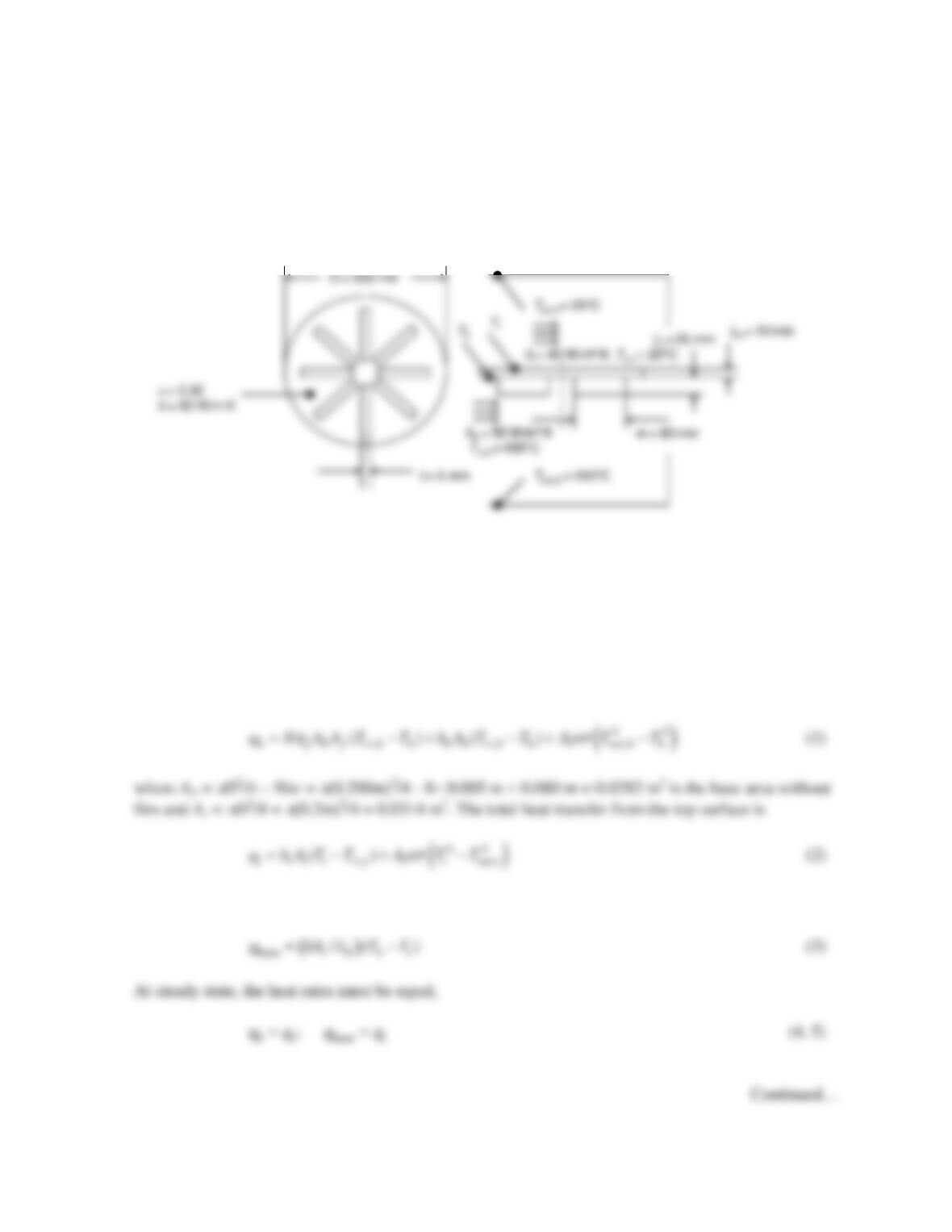
PROBLEM 3.116
KNOWN: Geometry of a cast iron burner with and without fins. Room temperature, combustion
temperature, heat transfer coefficient at the top burner surface, heat transfer coefficient at the bottom
burner surface, emissivity of burner coating, thermal conductivity of cast iron.
FIND: Temperature of the top burner surface with and without fins.
SCHEMATIC:
ASSUMPTIONS: (1) Steady–state, one-dimensional conditions, (2) Constant properties, (3)
Convection from fin tip, (4) Large surroundings at top and bottom of burner.
PROPERTIES: Given, Cast iron: k = 65 W/m⋅K.
ANALYSIS: Evaluating the radiation heat transfer from the combustion products to the bottom of
the burner as qrad,b =
εs
(πD2/4)(Tsur,b
4 – Tb
4), the total heat transfer to the bottom of the burner’s base is
One-dimensional conduction through the base of the burner is
PROBLEM 3.116 (Cont.)
The fin efficiency may be evaluated using Table 3.5. The corrected fin length is Lc = Lf + t/2 = 25 mm
Substituting values listed in the schematic, along with values of the various areas, the fin efficiency,
and N = 8 into Eqs. (1) through (5) and solving simultaneously yields
COMMENTS: (1) Adding fins to the bottom of the burner increases the steady-state top temperature
by approximately 30 degrees Celsius. (2) The finned burner heat rate is q = 597.2 W, while without
PROBLEM 3.117
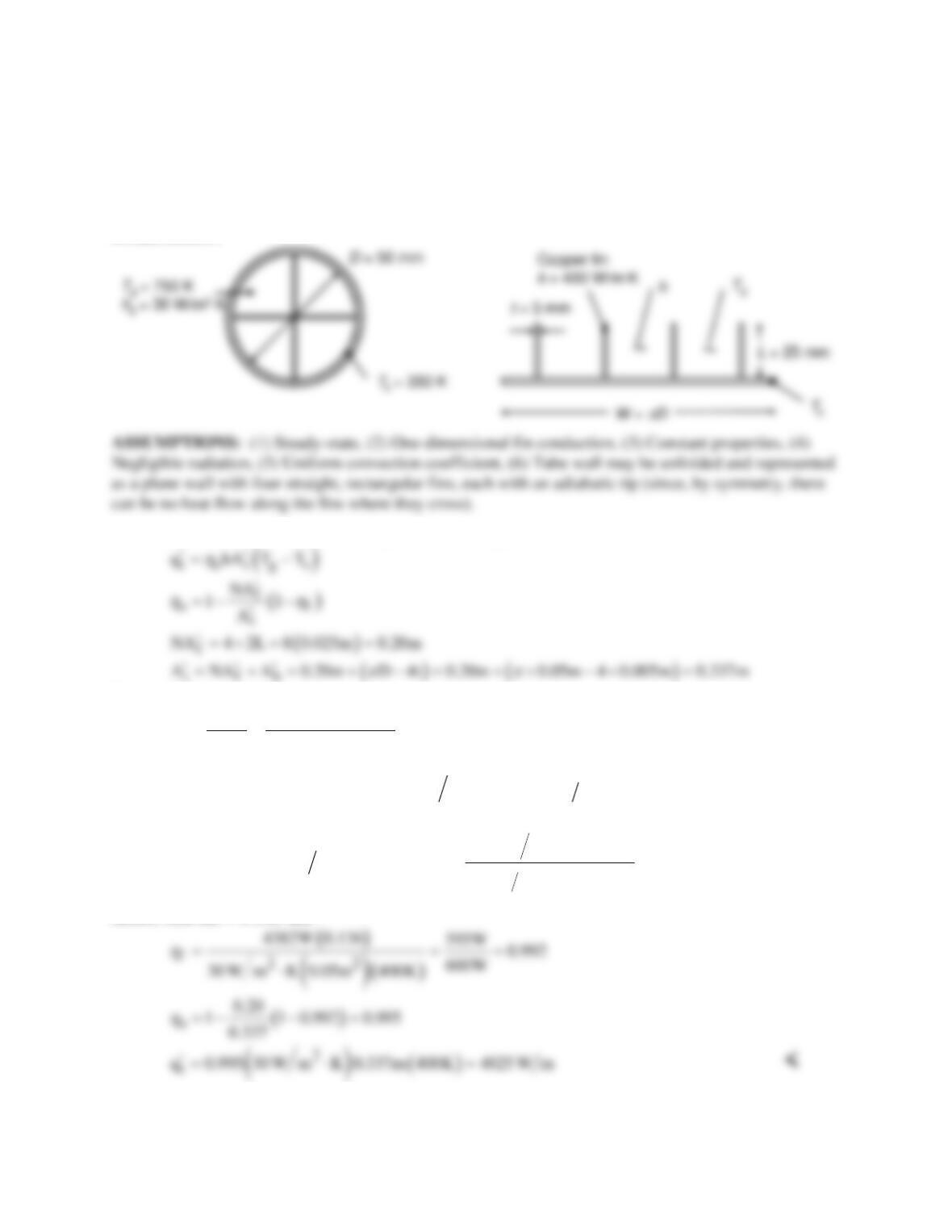
KNOWN: Diameter and internal fin configuration of copper tubes submerged in water. Tube wall
temperature and temperature and convection coefficient of gas flow through the tube.
FIND: Rate of heat transfer per tube length.
SCHEMATIC:
ANALYSIS: The rate of heat transfer per unit tube length is:
For an adiabatic fin tip,
( )
( )
f
f
max gs
q MtanhmL
qh 2L 1 T T
h
= = ⋅−
( ) ( )
[ ]
( )
( )
( )
( )
1/ 2
1/ 2 2 2
gs
M h2 1m t k 1m t T T 30 W m K 2m 400 W m K 0.005m 400K 4382W= + × −≈ ⋅ ⋅ =
( )
[ ]
( )
[ ]
{ }
( )
()
1/2
2
1/2
2
30 W m K 2m
mL h2 1m t k 1m t L 0.025m 0.137
400 W m K 0.005m
⋅
=+ ×≈ =
⋅
Hence, tanh mL = 0.136, and
COMMENTS: Alternatively,
( )
( )
t f t f gs
q 4q h A A T T
′ ′ ′′
=+− −
. Hence,
q′
= 4(595 W/m) + 30
W/m2⋅K (0.137 m)(400 K) = (2380 + 1644) W/m = 4024 W/m.
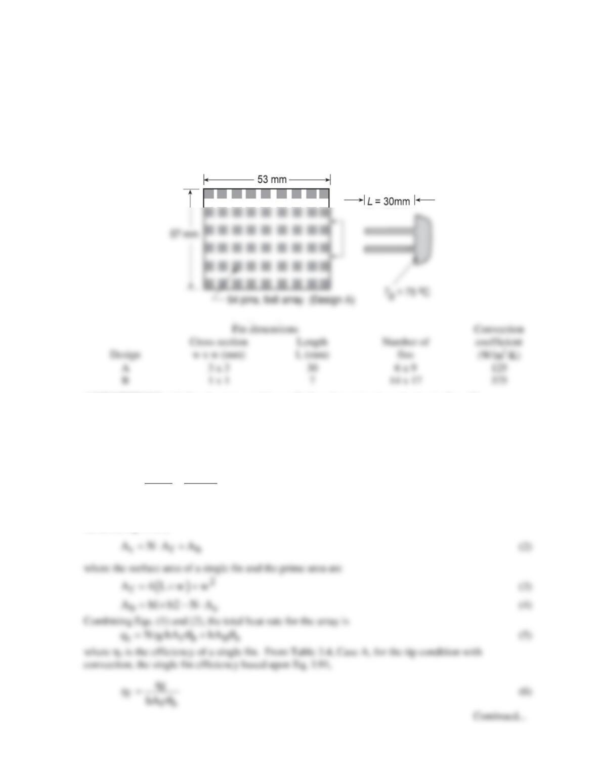
Problem 3.118
KNOWN: Two finned heat sinks, Designs A and B, prescribed by the number of fins in the array, N,
fin dimensions of square cross-section, w, and length, L, with different convection coefficients, h.
FIND: Determine which fin arrangement is superior. Calculate the heat rate, qf, efficiency, hf, and
effectiveness, εf, of a single fin, as well as, the total heat rate, qt, and overall efficiency, ho, of the
array. Also, compare the total heat rates per unit volume.
SCHEMATIC:
ASSUMPTIONS: (1) Steady-state conditions, (2) One-dimensional conduction in fins, (3)
Convection coefficient is uniform over fin and prime surfaces, (4) Fin tips experience convection,
and (5) Constant properties.
ANALYSIS: Following the treatment of Section 3.6.5, the overall efficiency of the array, Eq.
(3.103), is
tt
omax t b
qq
q hA
hq
= =
(1)
where At is the total surface area, the sum of the exposed portion of the base (prime area) plus the fin
surfaces, Eq. 3.104,
PROBLEM 3.118 (Cont.)
Additionally, we want to compare the performance of the designs with respect to the array volume,
( )
ft t
q q q b1 b2 L
′′′ = ∀= ⋅ ⋅
(12)
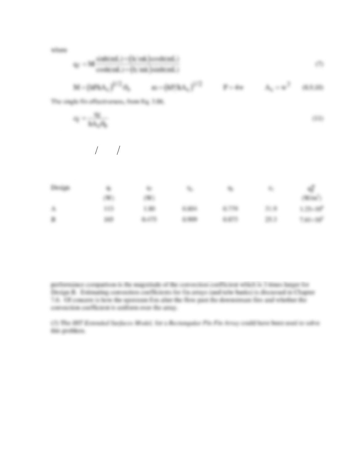
The above analysis was organized for easy treatment with equation–solving software. Solving Eqs.
(1) through (11) simultaneously with appropriate numerical values, the results are tabulated below.
COMMENTS: (1) Both designs have good efficiencies and effectiveness. Clearly, Design B is
superior because the heat rate is nearly 50% larger than Design A for the same board footprint.
Further, the space requirement for Design B is four times less (∀ = 2.12×10⁻⁵ vs. 9.06×10⁻⁵ m3) and
the heat rate per unit volume is 6 times greater.
(2) Design A features 54 fins compared to 238 fins for Design B. Also very significant to the
PROBLEM 3.119
KNOWN: Dimensions of a fin array and dust layer. Aluminum and dust thermal conductivities.
Base temperature. Air temperature and heat transfer coefficient.
FIND: Allowable heat rate for dust layer thickness in the range of 0 ≤ Ld ≤ 5 mm.
SCHEMATIC:
ASSUMPTIONS: (1) Steady-state, (2) Negligible temperature variation across fin thickness, (3)
Constant properties, (4) Uniform heat transfer coefficient, including over fin tips.
ANALYSIS: There are two heat transfer paths, one through the dust and into the air, and the other
through the fin. The thermal circuit is
The thermal resistances are given by
dd
d,cond
dd d p c
LL
R = =
k A k (A – NA )
T
= 25ºC
T
= 25ºC
T
= 25ºC
PROBLEM 3.119 (Cont.)
Here, m = (4h / kfw)1/2 = (4 × 375 W/m2∙K / 175 W/m∙K × 10-3 m)1/2 = 92.6 m-1
and Lf = L – Ld.
Finally,
q = qdust + qfin
<
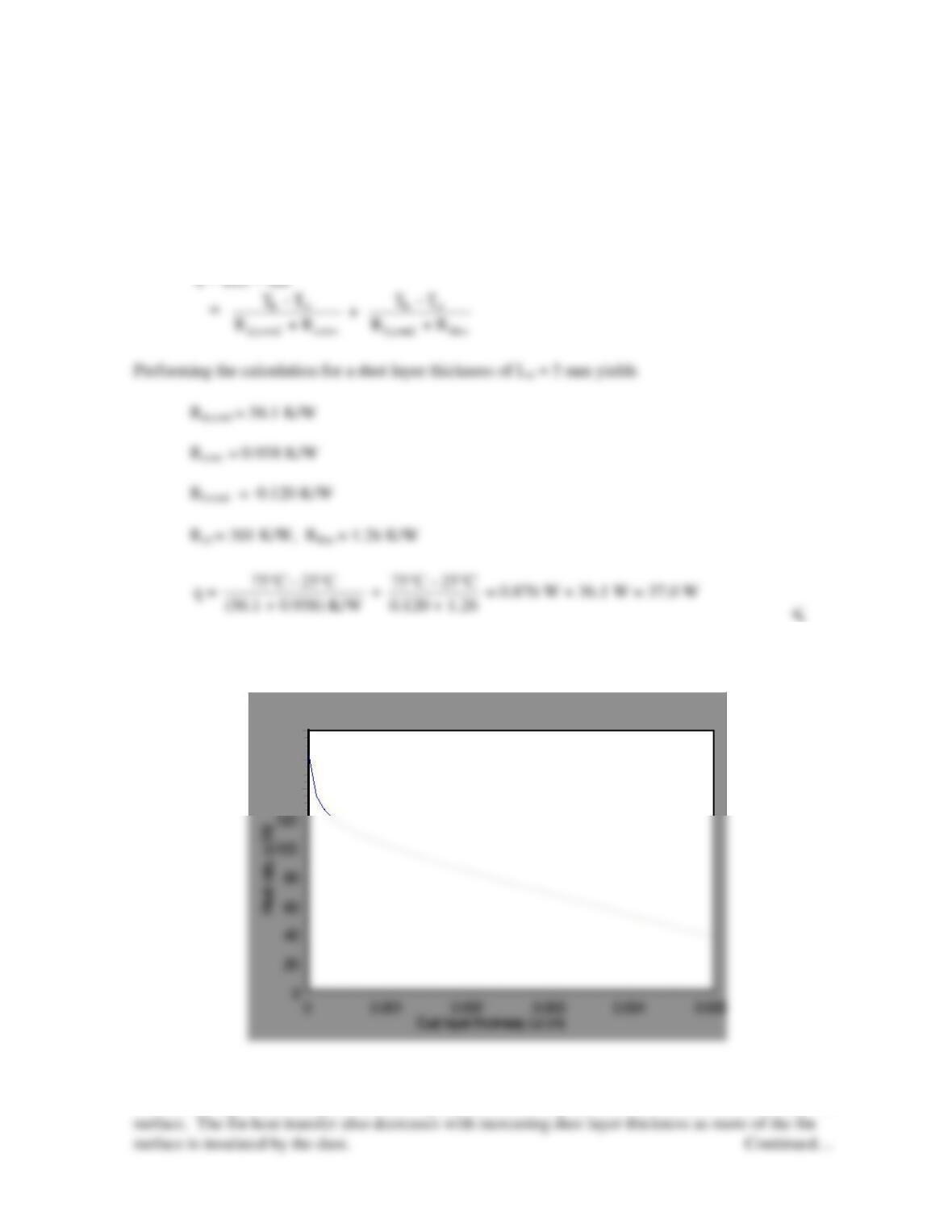
The figure shows the variation of the allowable heat rate as the dust layer thickness varies.
180
160
140
COMMENTS: The figure below shows the two contributions to the heat rate, qdust and qfin . The heat
transfer through the dust layer decreases rapidly as the dust layer thickness increases and insulates the
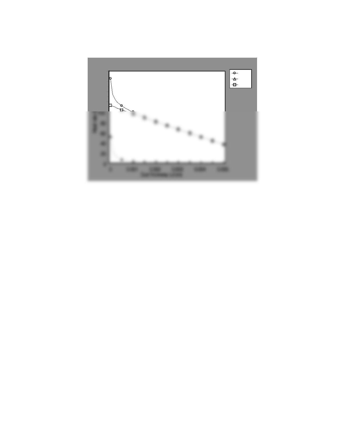
PROBLEM 3.119 (Cont.)
q
qdust
qf in
180
160
140
120
PROBLEM 3.120
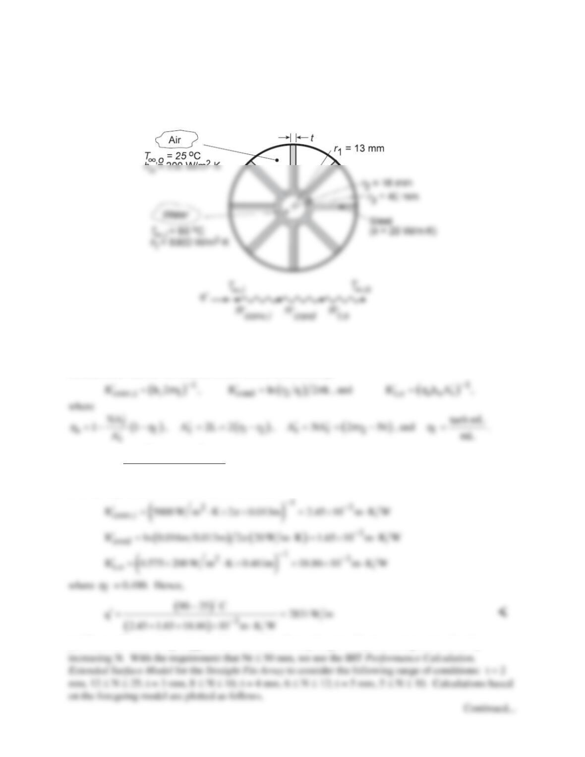
KNOWN: Geometrical and convection conditions of internally finned, concentric tube air heater.
FIND: (a) Thermal circuit, (b) Heat rate per unit tube length, (c) Effect of changes in fin array.
SCHEMATIC:
ASSUMPTIONS: (1) Steady-state conditions, (2) One-dimensional heat transfer in radial direction, (3)
Constant k, (4) Adiabatic outer surface.
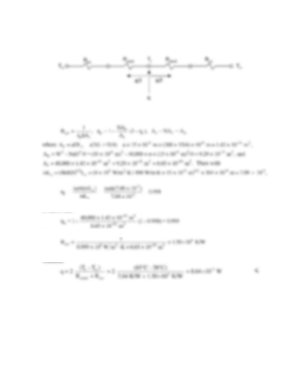
ANALYSIS: (a) For the thermal circuit shown schematically,
(b)
( )
,i ,o
conv,i cond t,o
TT
qR RR
∞∞
−
′=′ ′′
++
Substituting the known conditions, it follows that
f
h
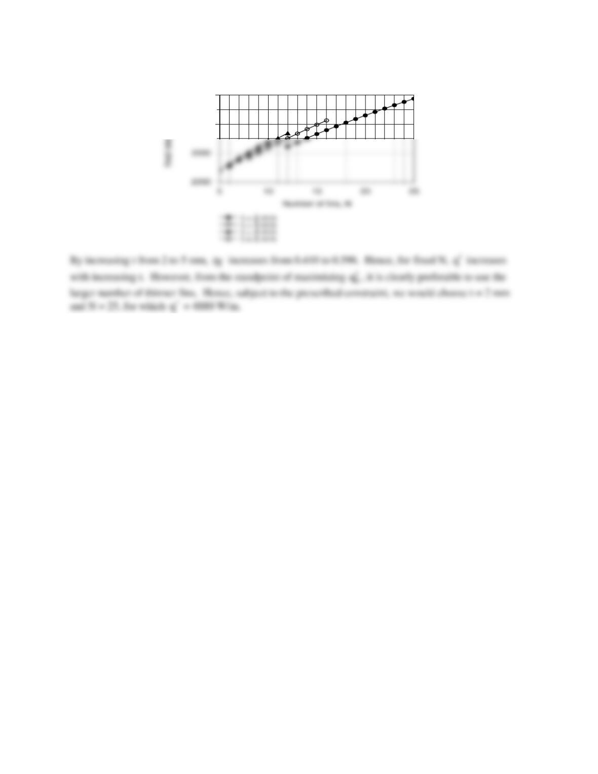
(c) The small value of
f
h
suggests that some benefit may be gained by increasing t, as well as by
PROBLEM 3.120 (Cont.)
4000
5000
COMMENTS: (1) The air side resistance makes the dominant contribution to the total resistance, and
efforts to increase
q′
by reducing
t,o
R′
are well directed. (2) A fin thickness any smaller than 2 mm
would be difficult to manufacture.