PROBLEM 3.1
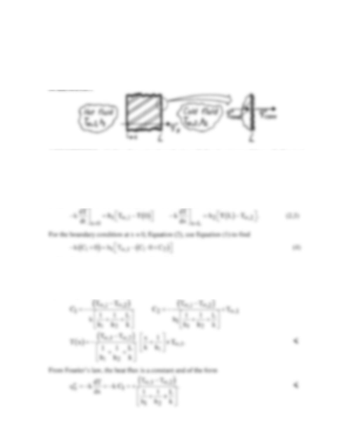
KNOWN: One-dimensional, plane wall separating hot and cold fluids at
T and T
,1 ,2∞ ∞ ,
respectively.
FIND: Temperature distribution, T(x), and heat flux,
′′
q
x
,
in terms of
T T h
,1 ,2 1∞ ∞
, , ,
h
2
,
k
and L.
ASSUMPTIONS: (1) One-dimensional conduction, (2) Steady-state conditions, (3) Constant
properties, (4) Negligible radiation, (5) No generation.
ANALYSIS: For the foregoing conditions, the general solution to the heat diffusion equation
is of the form, Equation 3.2,
( )
12
T x Cx C .= +
(1)
The constants of integration, C1 and C2, are determined by using surface energy balance
conditions at x = 0 and x = L, Equation 2.34, and as illustrated above,
and for the boundary condition at x = L to find
( ) ( )
1 2 1 2 ,2
k C 0 h CL C T .
∞
− += + −
(5)
Multiply Eq. (4) by h2 and Eq. (5) by h1, and add the equations to obtain C1. Then substitute
C1 into Eq. (4) to obtain C2. The results are
PROBLEM 3.2
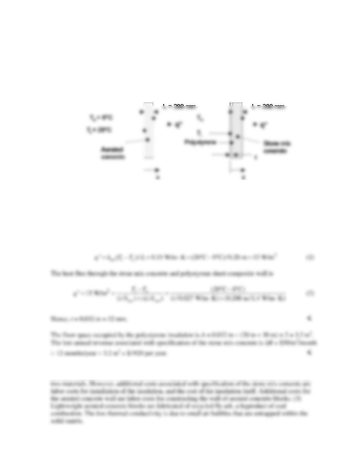
KNOWN: Thickness of basement wall. Inner and outer wall temperatures. Thermal conductivity of
aerated concrete.
FIND: Thickness of polystyrene insulation needed to reduce heat flux through the stone mix concrete
wall to that of the aerated concrete wall. Lost annual rental income associated with specification of the
stone mix concrete wall.
SCHEMATIC:
ASSUMPTIONS: (1) Steady–state, one-dimensional conduction, (2) Constant properties, (3)
Negligible contact resistance.
PROPERTIES: Table A.3, Stone mix concrete (300 K): ksm = 1.4 W/m⋅K; Rigid extruded
polystyrene sheet (285 K,
ρ
= 35 kg/m3): kps = 0.027 W/m⋅K. Aerated concrete: kac = 0.15 W/m⋅K
(given).
ANALYSIS: The heat flux through the aerated concrete is
COMMENTS: (1) Inclusion of the thermal contact resistance will reduce the value of the required
insulation thickness. (2) A careful economic analysis would account for the difference in cost of the
PROBLEM 3.3
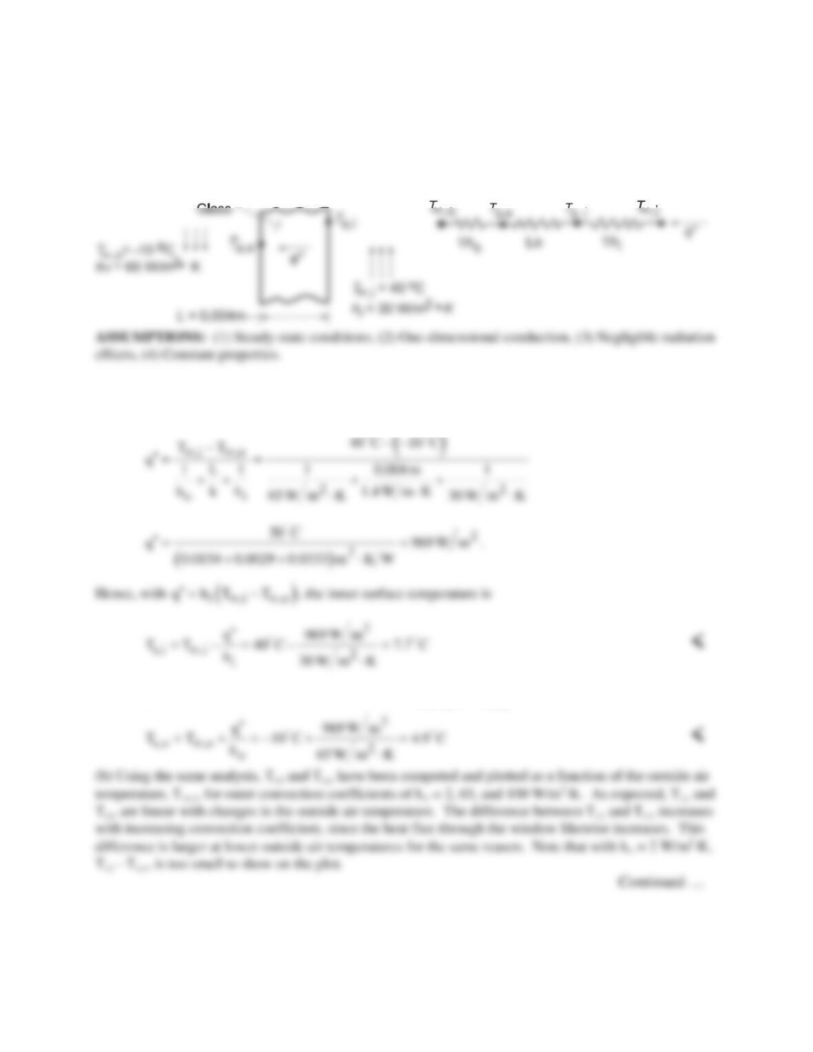
KNOWN: Temperatures and convection coefficients associated with air at the inner and outer surfaces
of a rear window.
FIND: (a) Inner and outer window surface temperatures, Ts,i and Ts,o, and (b) Ts,i and Ts,o as a function
of the outside air temperature T∞,o and for selected values of outer convection coefficient, ho.
SCHEMATIC:
PROPERTIES: Table A-3, Glass (300 K): k = 1.4 W/m⋅K.
ANALYSIS: (a) The heat flux may be obtained from Eqs. 3.11 and 3.12,
Similarly for the outer surface temperature with
( )
o s,o ,o
q hT T
∞
′′ = −
find
PROBLEM 3.3 (Cont.)
20
30
40
Tsi or Tso; ho = 2 W/m^.K
COMMENTS: (1) The largest resistance is that associated with convection at the inner surface. The
values of Ts,i and Ts,o could be increased by increasing the value of hi.
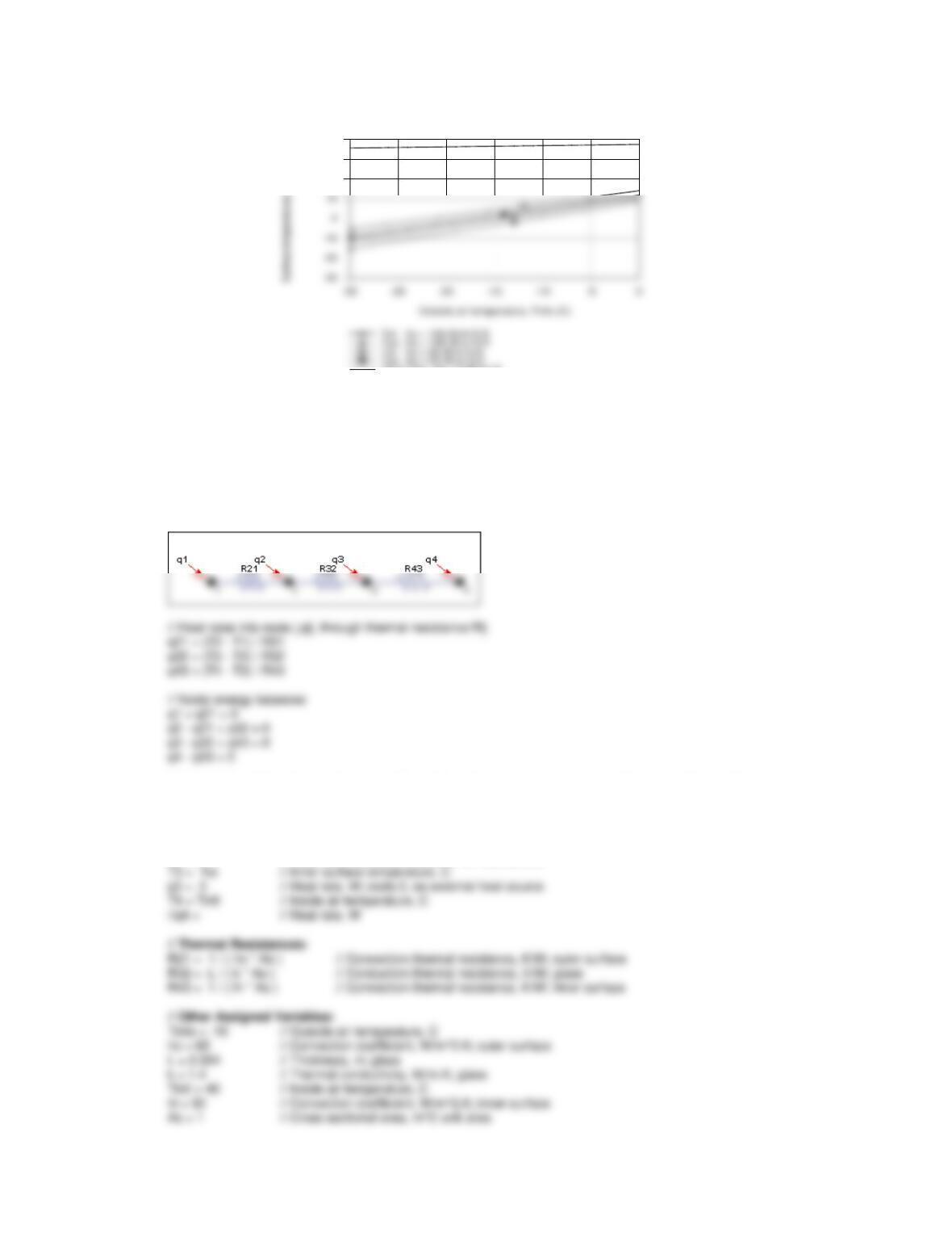
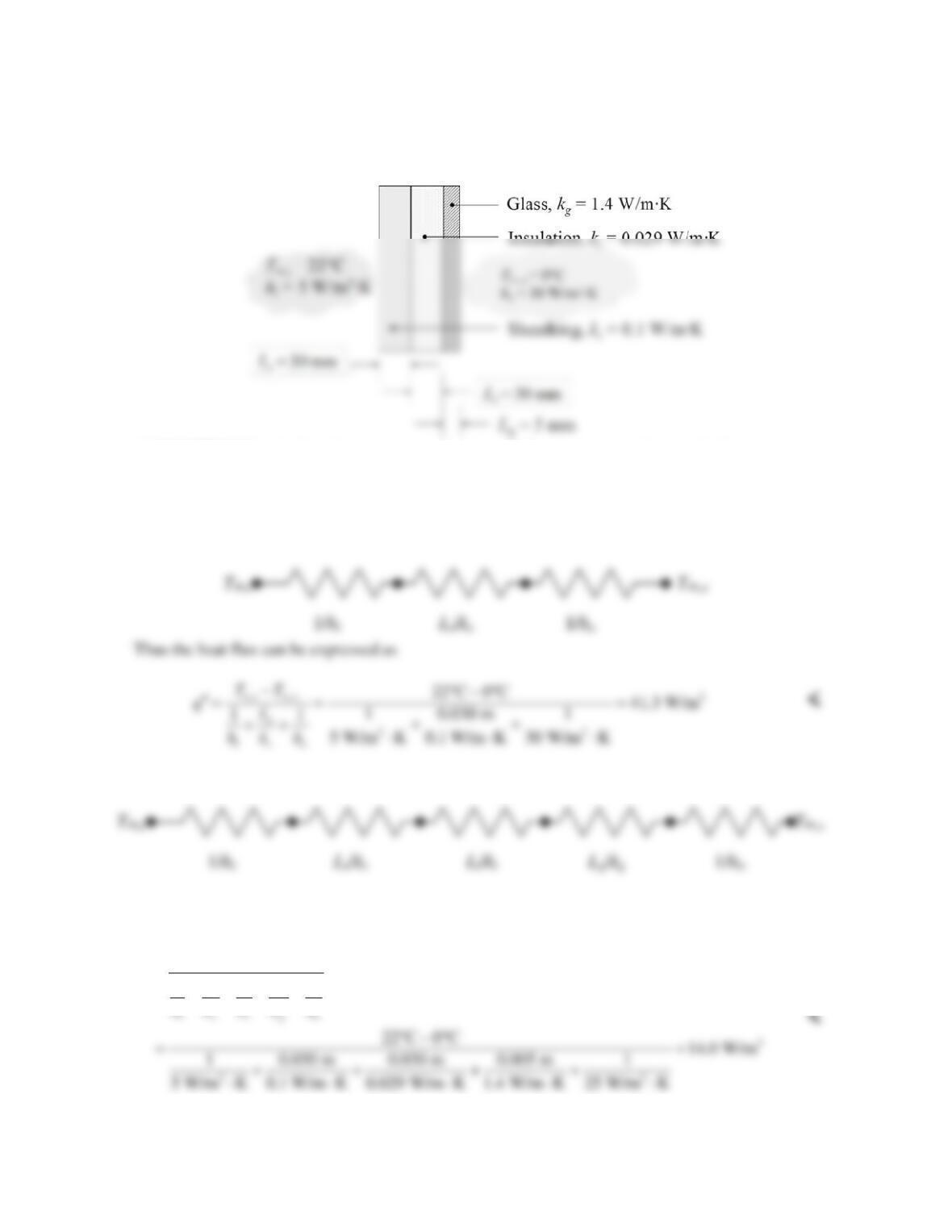
(2) The IHT Thermal Resistance Network Model was used to create a model of the window and generate
the above plot. The Workspace is shown below.
// Thermal Resistance Network Model:
// The Network:
/* Assigned variables list: deselect the qi, Rij and Ti which are unknowns; set qi = 0 for embedded nodal points
at which there is no external source of heat. */
T1 = Tinfo // Outside air temperature, C
//q1 = // Heat rate, W
T2 = Tso // Outer surface temperature, C
q2 = 0 // Heat rate, W; node 2, no external heat source
PROBLEM 3.4
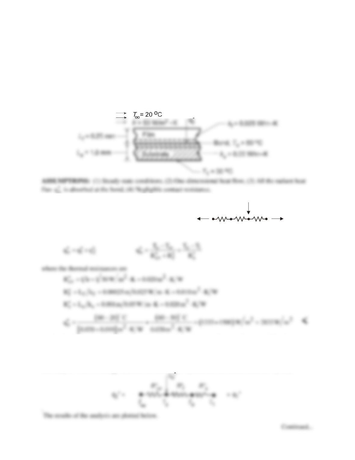
KNOWN: Thermal conductivities and thicknesses of original wall, insulation layer, and glass layer.
Interior and exterior air temperatures and convection heat transfer coefficients.
FIND: Heat flux through original and retrofitted walls.
SCHEMATIC:
ASSUMPTIONS: (1) One–dimensional conduction, (2) Steady-state conditions, (3) Constant
properties, (4) Negligible contact resistances.
ANALYSIS: The original wall with convection inside and outside can be represented by the
following thermal resistance network, where the resistances are each for a unit area:
The retrofitted wall has three layers. The thermal circuit can be represented as follows:
Thus the heat flux can be expressed as
,,
11
io
g
si
TT
qL
LL
hk kk h
∞∞
−
′′ =
+++ +
COMMENTS: The heat flux has been reduced to approximately one-third of the original value
because of the increased resistance, which is mainly due to the insulation layer.
PROBLEM 3.5
KNOWN: Curing of a transparent film by radiant heating with substrate and film surface subjected to
known thermal conditions.
FIND: (a) Thermal circuit for this situation, (b) Radiant heat flux,
o
q′′
(W/m2), to maintain bond at
curing temperature, To, (c) Compute and plot
o
q′′
as a function of the film thickness for 0 ≤ Lf ≤ 1 mm,
and (d) If the film is not transparent, determine
o
q′′
required to achieve bonding; plot results as a function
of Lf.
SCHEMATIC:
ANALYSIS: (a) The thermal circuit
for this situation is shown at the right.
Note that terms are written on a per unit
area basis.
R”
s
T
s
T
o
T
1
R”
f
q”
1
q”
2
q”
o
R”
cv
T
o
o
(b) Using this circuit and performing an energy balance on the film-substrate interface,
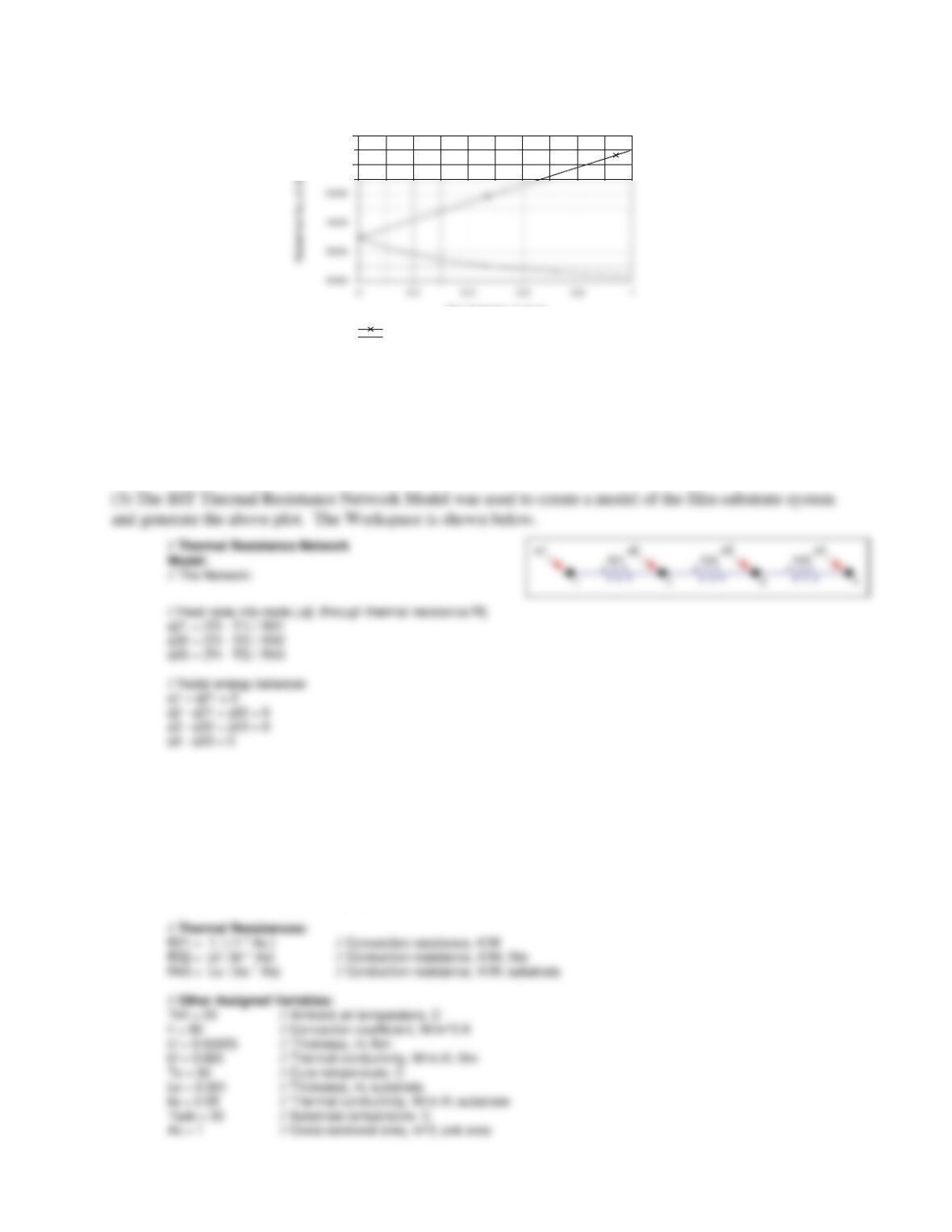
(c) For the transparent film, the radiant flux required to achieve bonding as a function of film thickness
Lf is shown in the plot below.
(d) If the film is opaque (not transparent), the thermal circuit is shown below. In order to find
o
q′′
, it is
necessary to write two energy balances, one around the Ts node and the second about the To node.
o
PROBLEM 3.5 (Cont.)
Film thickness, Lf (mm)
6000
7000
Opaque film
Transparent film
COMMENTS: (1) When the film is transparent, the radiant flux is absorbed on the bond. The flux
required decreases with increasing film thickness. Physically, how do you explain this? Why is the
relationship not linear?
(2) When the film is opaque, the radiant flux is absorbed on the surface, and the flux required increases
with increasing thickness of the film. Physically, how do you explain this? Why is the relationship
linear?
/* Assigned variables list: deselect the qi, Rij and Ti which are unknowns; set qi = 0 for embedded nodal points
at which there is no external source of heat. */
T1 = Tinf // Ambient air temperature, C
//q1 = // Heat rate, W; film side
T2 = Ts // Film surface temperature, C
q2 = 0 // Radiant flux, W/m^2; zero for part (a)
T3 = To // Bond temperature, C
q3 = qo // Radiant flux, W/m^2; part (a)
T4 = Tsub // Substrate temperature, C
//q4 = // Heat rate, W; substrate side
PROBLEM 3.6
KNOWN: Composite wall with known properties and prescribed convection processes at
inner and outer surfaces.
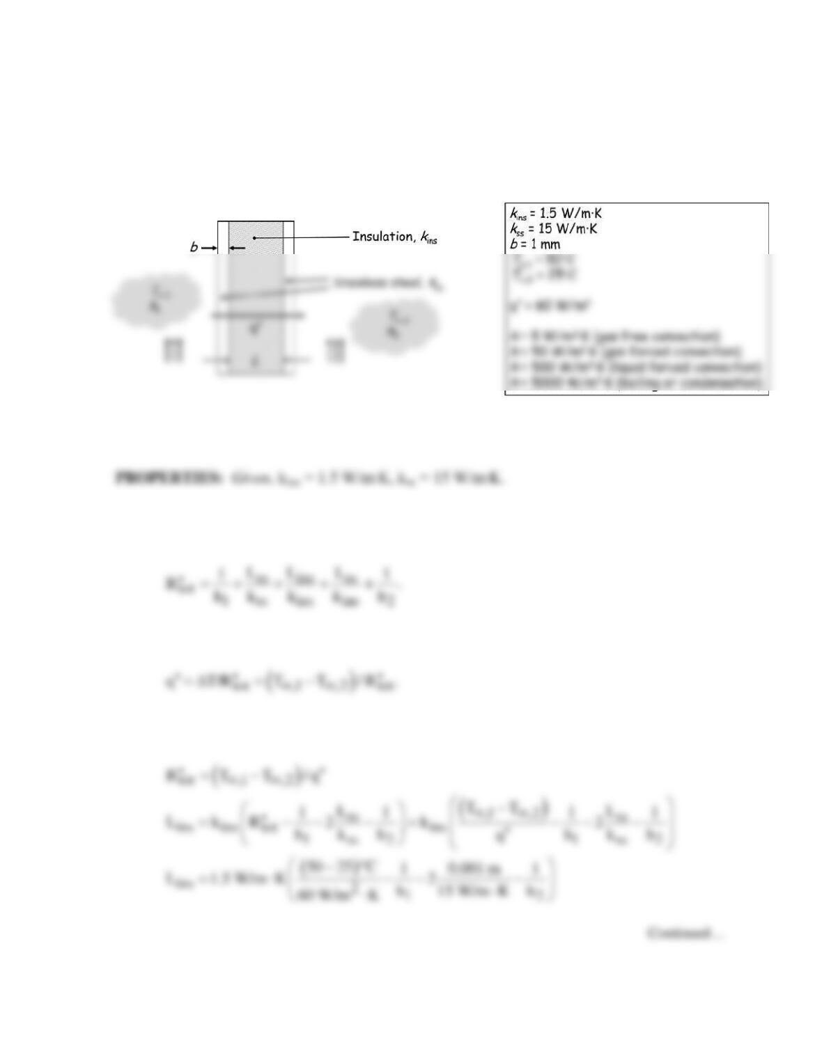
FIND: Required insulation thickness to limit heat flux to 60 W/m2.
SCHEMATIC:
ASSUMPTIONS: (1) One-dimensional conduction, (2) Steady-state conditions, (3)
Negligible contact resistance.
ANALYSIS: The expression for the total thermal resistance for a unit area of the composite
wall follows from Eq. 3.18.
The heat flux through the wall is
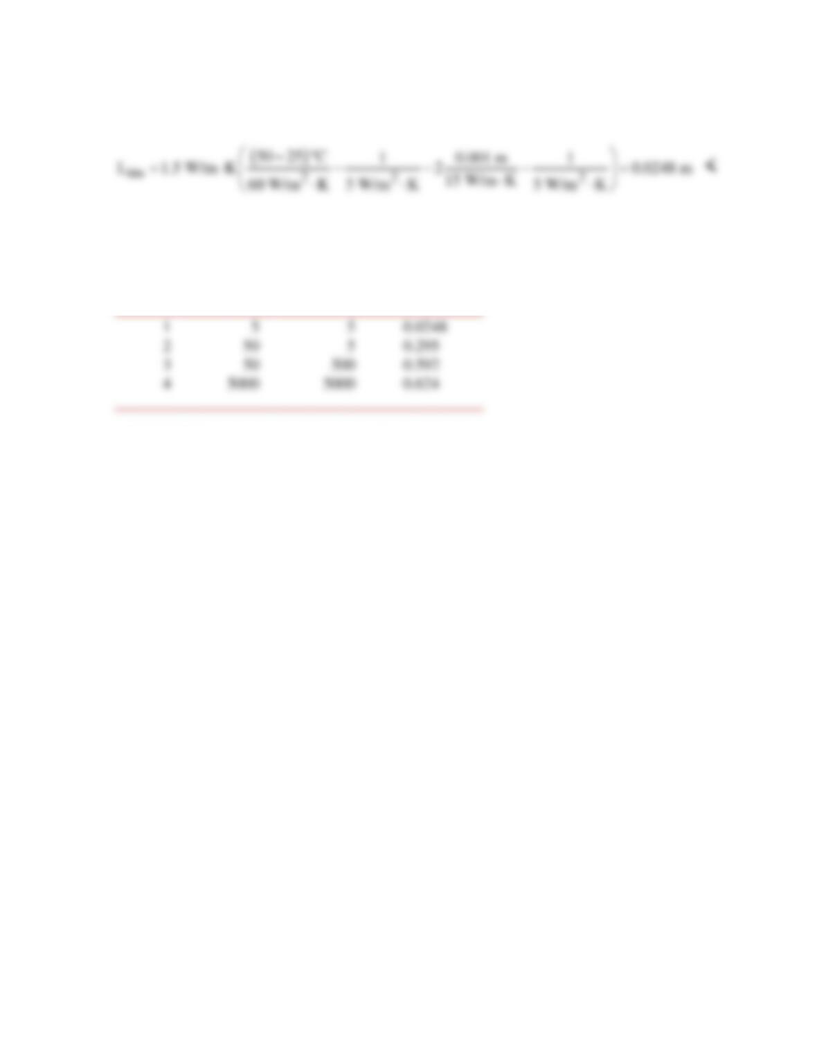
The requirement that
q′′
= 60 W/m2 determines the required
tot
R′′
and insulation thickness:
PROBLEM 3.6 (Cont.)
For Case 1, h1 = h2 = 5 W/m2⋅K, and the insulation thickness is:
The other cases can be calculated similarly and the results are shown in the table.
______________________________________________
Case h1 (W/m2∙K) h2 (W/m2∙K) Lins (m) <
______________________________________________
COMMENTS: As the heat transfer coefficients increase, the required insulation thickness
increases. As the heat transfer coefficients approach infinity, the maximum required insulation
thickness is 0.625 m.
PROBLEM 3.7
KNOWN: Top and bottom temperatures applied to a water layer of known thickness.
FIND: Steady–state location of the solid–liquid interface.
SCHEMATIC:
ASSUMPTIONS: (1) Steady–state conditions, (2) Constant properties, (3) Negligible radiation, (4)
Negligible convection in the liquid.
PROPERTIES: Table A.6, liquid water (T = 273 K): kf = 0.569 W/m⋅K; Table A.3, ice (T = 0 K), ks
= 1.88 W/m⋅K.
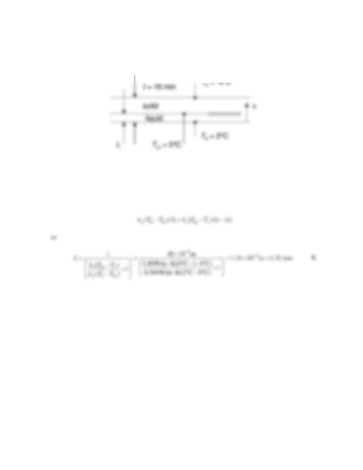
ANALYSIS: An energy balance at the control surface shown in the schematic yields
COMMENTS: (1) Liquid water is opaque to thermal radiation, but ice is semi-transparent. A more
detailed analysis would account for the effects of radiation. (2) Free convection in the liquid is
negligible because the density of liquid water at Th = 2°C is greater than the density at Tm = 0°C.
Water is one of only several liquids that experiences such a density inversion.
PROBLEM 3.8
KNOWN: Design and operating conditions of a heat flux gage.
FIND: (a) Convection coefficient for water flow (Ts = 27°C) and error associated with neglecting
SCHEMATIC:
ASSUMPTIONS: (1) Steady-state, (2) One-dimensional conduction, (3) Constant k.
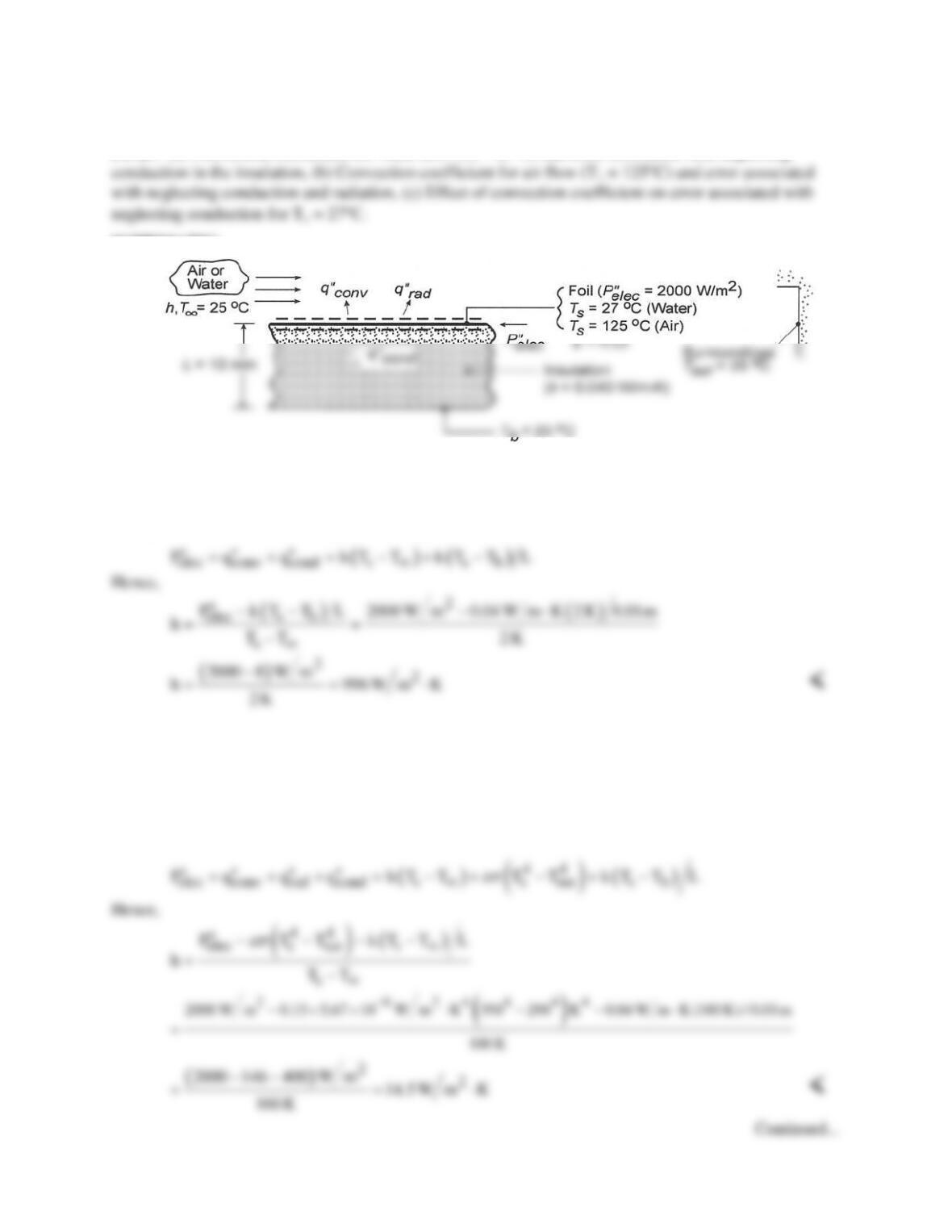
ANALYSIS: (a) The electric power dissipation is balanced by convection to the water and conduction
through the insulation. An energy balance applied to a control surface about the foil therefore yields
If conduction is neglected, a value of h = 1000 W/m2⋅K is obtained, with an attendant error of (1000 –
996)/996 = 0.40%
(b) In air, energy may also be transferred from the foil surface by radiation, and the energy balance
yields
PROBLEM 3.8 (Cont.)
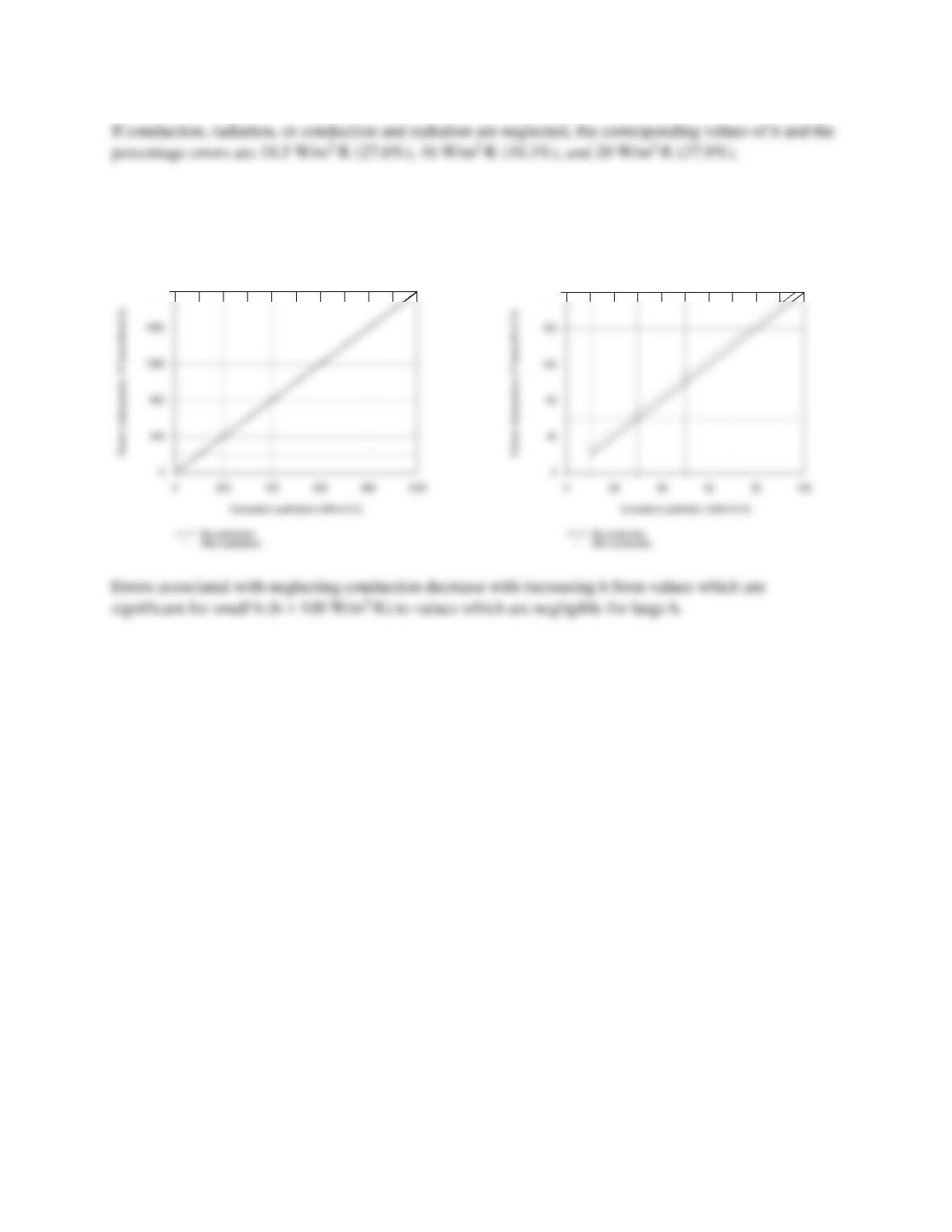
(c) For a fixed value of Ts = 27°C, the conduction loss remains at
cond
q′′
= 8 W/m2, which is also the
fixed difference between
elec
P′′
and
conv
q′′
. Although this difference is not clearly shown in the plot for
10 ≤ h ≤ 1000 W/m2⋅K, it is revealed in the subplot for 10 ≤ 100 W/m2⋅K.
2000
200
COMMENTS: In liquids (large h), it is an excellent approximation to neglect conduction and assume
that all of the dissipated power is transferred to the fluid.
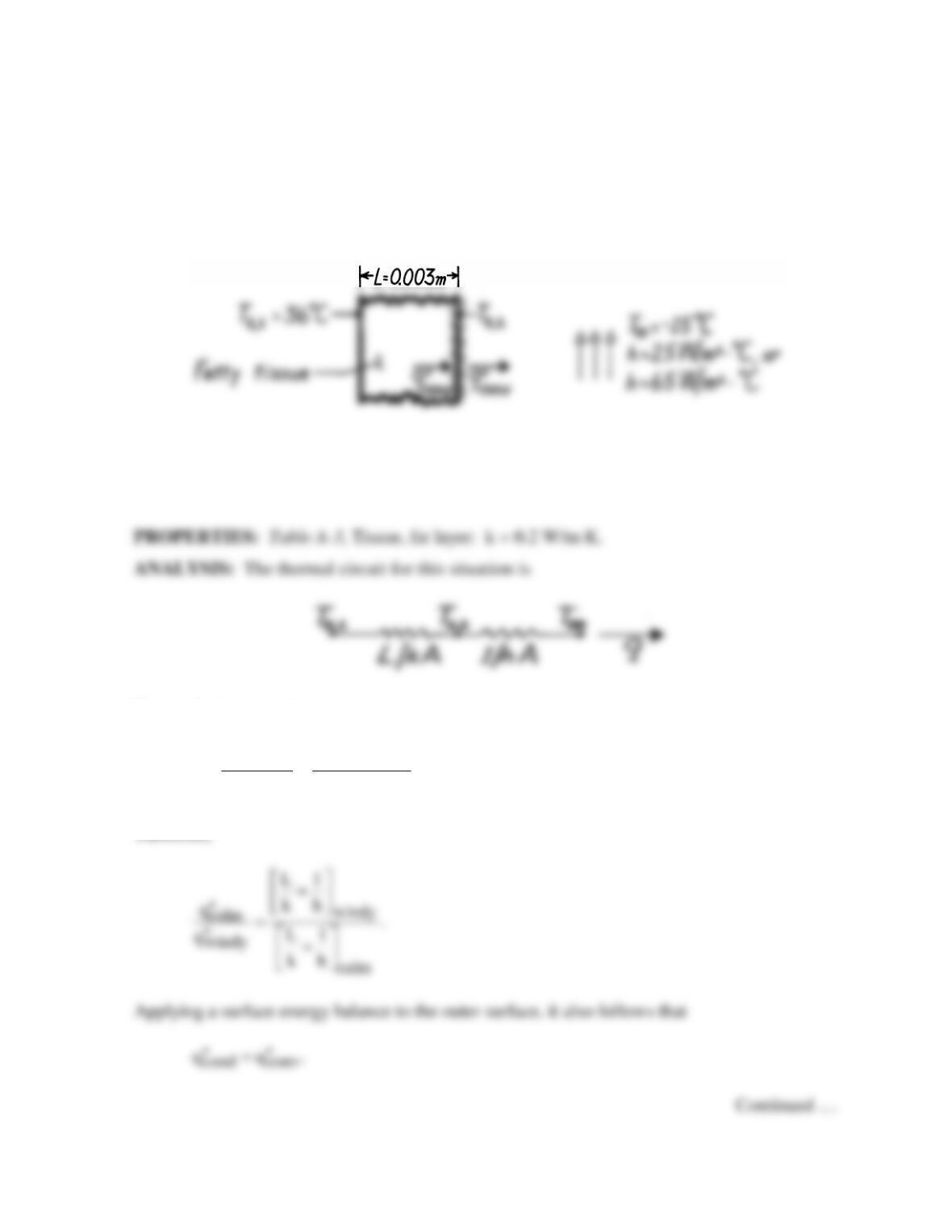
PROBLEM 3.9
KNOWN: A layer of fatty tissue with fixed inside temperature can experience different
outside convection conditions.
FIND: (a) Ratio of heat loss for different convection conditions, (b) Outer surface
temperature for different convection conditions, and (c) Temperature of still air which
achieves same cooling as moving air (wind chill effect).
SCHEMATIC:
ASSUMPTIONS: (1) One-dimensional conduction through a plane wall, (2) Steady–state
conditions, (3) Homogeneous medium with constant properties, (4) No internal heat
generation (metabolic effects are negligible), (5) Negligible radiation effects.
Hence, the heat rate is
s,1 s,1
tot
TT TT
q.
R L/kA 1/ hA
∞∞
−−
= = +
Therefore,
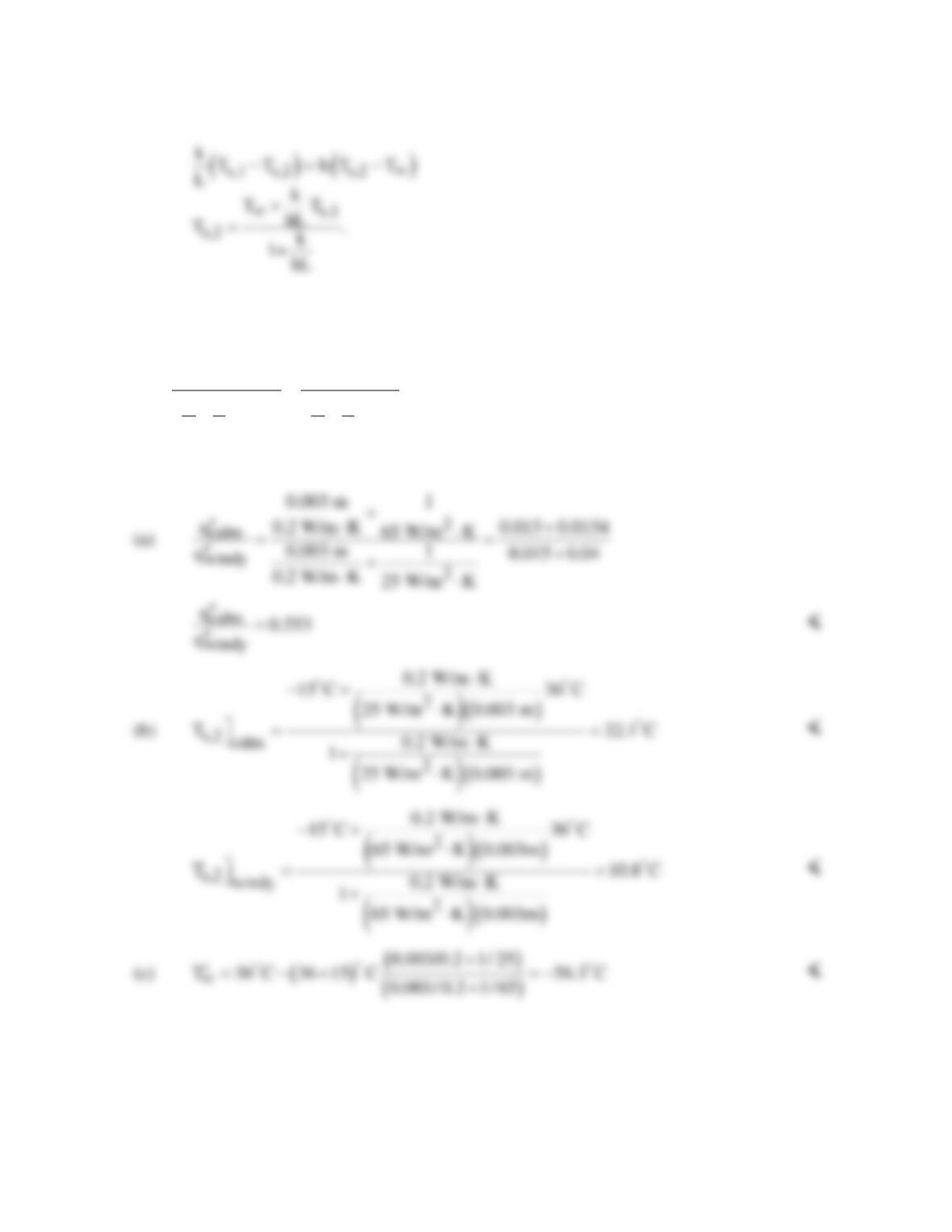
PROBLEM 3.9 (Cont.)
Hence,
To determine the wind chill effect, we must determine the heat loss for the windy day and use
it to evaluate the hypothetical ambient air temperature,
′
∞
T ,
which would provide the same
heat loss on a calm day, Hence,
s,1 s,1
windy calm
TT TT
qL1 L1
kh kh
∞∞
′
−−
′′ = =
++
From these relations, we can now find the results sought:
COMMENTS: The wind chill effect is equivalent to a decrease of Ts,2 by 11.3°C and
increase in the heat loss by a factor of (0.553)–1 = 1.81.
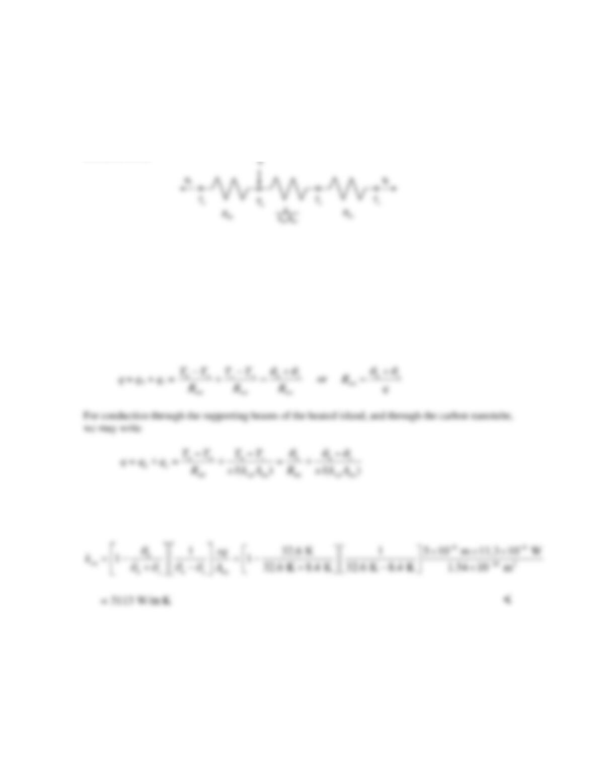
PROBLEM 3.10
KNOWN: Temperature of the heating island and sensing island, as well as the surrounding silicon
nitride wafer temperature of Example 3.4.
FIND: The thermal conductivity of the carbon nanotube, kcn, for the conditions of the problem
statement and Th = 332.6 K, without evaluating the thermal resistances of the supports.
SCHEMATIC:
ASSUMPTIONS: (1) Steady–state conditions, (2) Constant properties, (3) One-dimensional heat
transfer, (4) Isothermal heating and sensing islands, (5) Negligible radiation and convection effects.
ANALYSIS: We begin by defining an excess temperature,
θ
≡ T – T∞ and modifying the thermal
circuit as shown in the schematic. In the modified circuit, the total thermal resistance, Rtot, represents
the combined effects of the two beams that support either the heated island or the sensing island.
From the modified thermal circuit, it is evident that an expression for Rtot can be derived as
Substituting the expression for Rtot into the preceding equation, and rearranging the resulting
expression yields
COMMENTS: (1) The analysis is simplified if the heating island temperature is known. (2) This
solution is independent of the thermal resistance posed by the support beams, making the measured
thermal conductivity of the carbon nanotube less susceptible to experimental error.
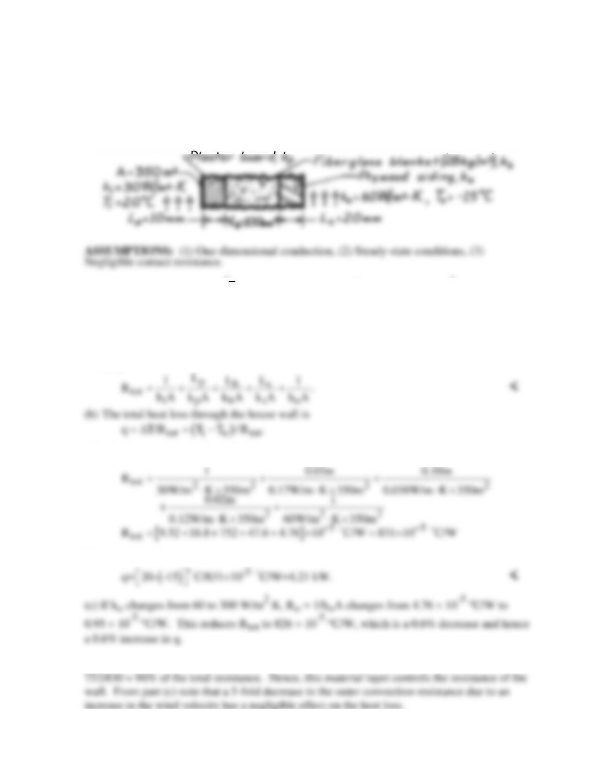
PROBLEM 3.11
KNOWN: Composite wall of a house with prescribed convection processes at inner and
outer surfaces.
FIND: (a) Expression for thermal resistance of house wall, Rtot; (b) Total heat loss, q(W); (c)
Effect on heat loss due to increase in outside heat transfer convection coefficient, ho; and (d)
Controlling resistance for heat loss from house.
SCHEMATIC:
PROPERTIES: Table A-3,
( ) ( )
( )
io
T T T / 2 20 15 C/2=2.5 C 300K :=+=− ≈
Fiberglass
blanket, 28 kg/m3, kb = 0.038 W/m⋅K; Plywood siding, ks = 0.12 W/m⋅K; Plasterboard, kp =
0.17 W/m⋅K.
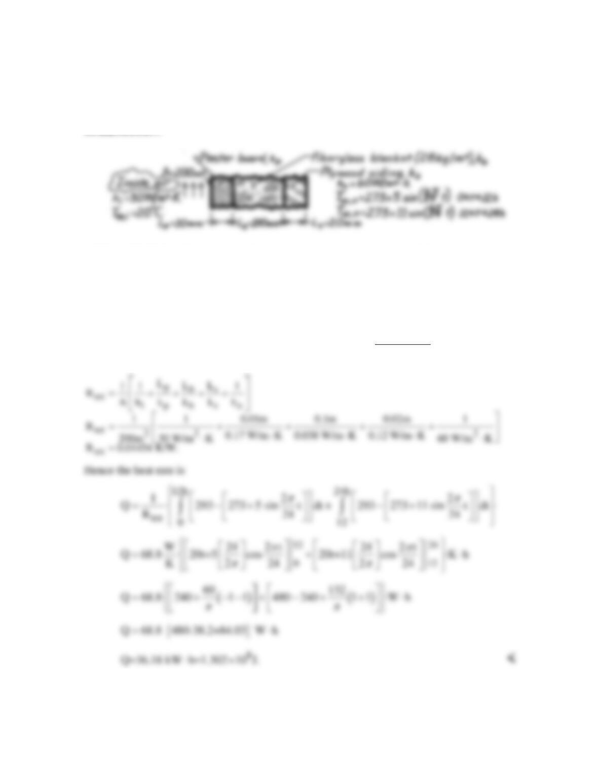
ANALYSIS: (a) The expression for the total thermal resistance of the house wall follows
from Eq. 3.18.
Substituting numerical values, find
The heat loss is then,
(d) From the expression for Rtot in part (b), note that the insulation resistance, Lb/kbA, is
PROBLEM 3.12
KNOWN: Composite wall of a house with prescribed convection processes at inner and
outer surfaces.
FIND: Daily heat loss for prescribed diurnal variation in ambient air temperature.
SCHEMATIC:
ASSUMPTIONS: (1) One-dimensional, steady-state conduction (negligible change in wall
thermal energy storage over 24h period), (2) Negligible contact resistance.
PROPERTIES: Table A-3, T ≈ 300 K: Fiberglas blanket (28 kg/m3), kb = 0.038 W/m⋅K;
Plywood, ks = 0.12 W/m⋅K; Plasterboard, kp = 0.17 W/m⋅K.
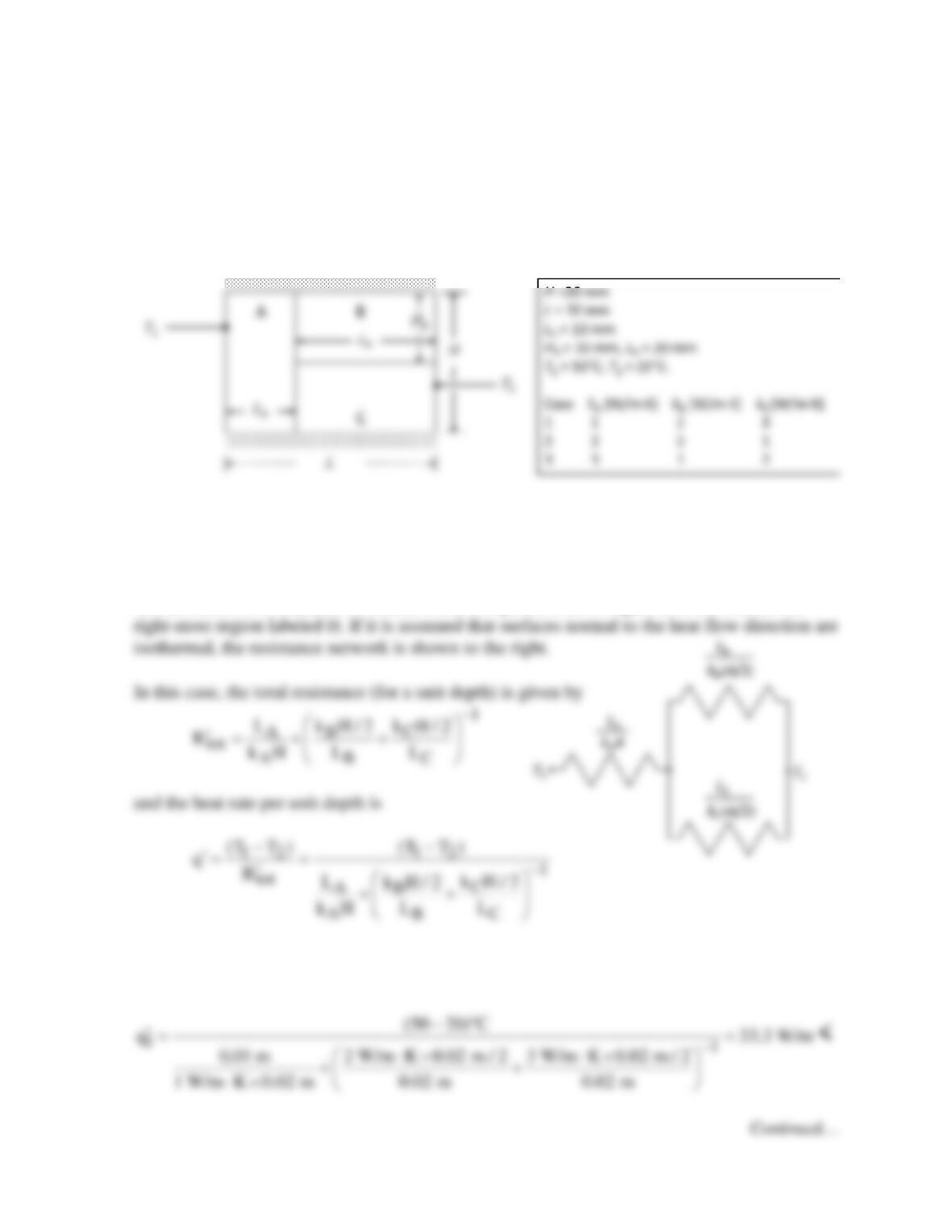
ANALYSIS: The heat loss may be approximated as
24h ,i ,o
tot
0
TT
Q dt where
R
∞∞
−
=∫
COMMENTS: From knowledge of the fuel cost, the total daily heating bill could be
determined. For example, at a cost of 0.18$/kW⋅h, the heating bill would be $6.52/day.
PROBLEM 3.13
KNOWN: Composite wall with known dimensions and thermal conductivities.
FIND: Heat rate per unit wall depth, and which of three cases yields the largest and smallest
heat rates.
SCHEMATIC:
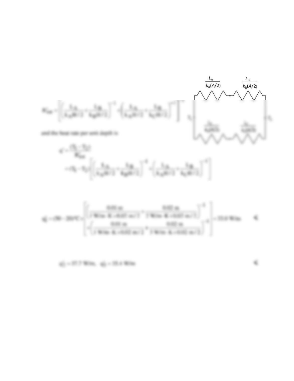
ASSUMPTIONS: (1) Surfaces normal to heat flow direction are isothermal or surfaces
parallel to the heat flow direction are adiabatic, (2) Steady-state conditions, (3) Negligible
contact resistance.
ANALYSIS: This scenario is similar to the composite wall of Figure 3.3, but without the
Substituting values for Case 1 yields
PROBLEM 3.13 (Cont.)
Repeating the calculation for the two other cases yields
23
q 40.0 W/m, q 36.0 W/m
′′
= =
<
On the other hand, if it is assumed that surfaces parallel to the heat flow direction are
adiabatic, the resistance network is shown to the right.
In this case, the total resistance (for a unit depth) is given by
Substituting values for Case 1 yields
Repeating the calculation for the two other cases yields
COMMENTS: The results are quite close between the two different methods for
approximating the thermal resistance network. This is because the thermal conductivities of
the three materials are the same order of magnitude. If the thermal conductivities differed
more dramatically, the results of the two methods wouldn’t agree as well.
PROBLEM 3.14
KNOWN: Dimensions and materials associated with a composite wall (2.5m × 6.5m, 10 studs each
2.5m high).
FIND: Wall thermal resistance.
SCHEMATIC:
PROPERTIES: Table A-3 (T ≈ 300K): Hardwood siding, kA = 0.094 W/m⋅K; Hardwood,
kB = 0.16 W/m⋅K; Gypsum, kC = 0.17 W/m⋅K; Insulation (glass fiber paper faced, 28 kg/m3),
kD = 0.038 W/m⋅K.
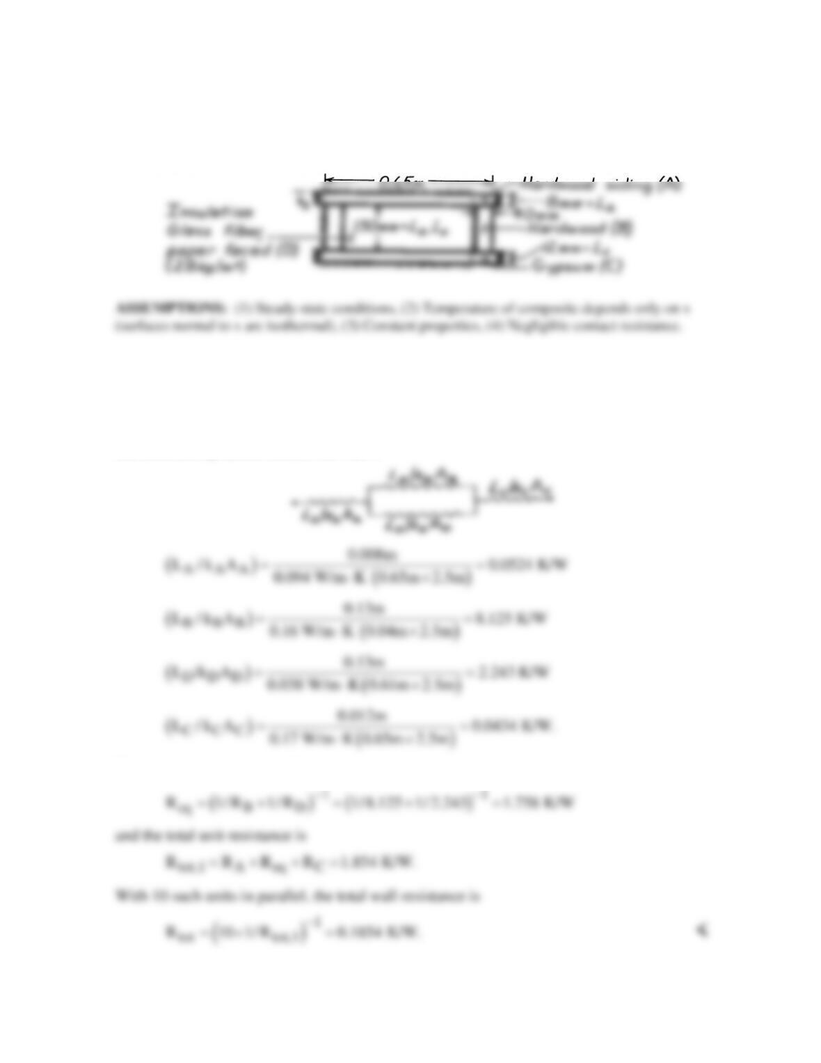
ANALYSIS: Using the isothermal surface assumption, the thermal circuit associated with a single
unit (enclosed by dashed lines) of the wall is
The equivalent resistance of the core is
COMMENTS: If surfaces parallel to the heat flow direction are assumed adiabatic, the thermal
circuit and the value of Rtot will differ.