PROBLEM 3.131 (Cont.)
The total thermal resistance is given by
where Equation 3.108 has been used to express the overall fin resistance. From Equations 3.104,
3.107, and 3.95,
Thus,
PROBLEM 3.131 (Cont.)
The system of equations from part (a) applies here, except that Equations 3 and 4 are replaced by the
revised versions
tot
Equations 1, 2, 3r, 4r, and 5 may be solved simultaneously to yield I = 2.04 A, and
COMMENTS: By adding the two heat sinks to the thermoelectric module, the power produced by the
module increases by a factor of 28. Not only does the power depend on the semiconductor properties
of the thermoelectric material, but also strongly on the thermal management of the module through, as
in this problem, addition of heat sinks.
PROBLEM 3.132
KNOWN: Dimensions of thermoelectric module. Convection conditions, thermoelectric module
performance parameters, load electrical resistance, contact resistance between thermoelectric module
and stove surface, emissivity of the exposed surface of the thermoelectric module, temperature of
surroundings.
FIND: Sketch of the equivalent thermal circuit and electrical power generated by the module.
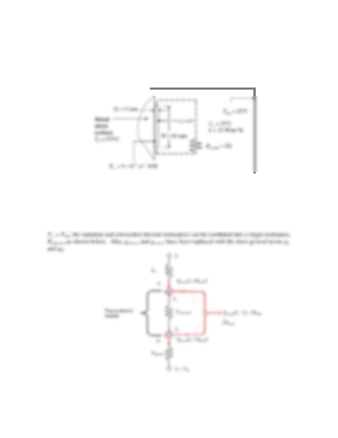
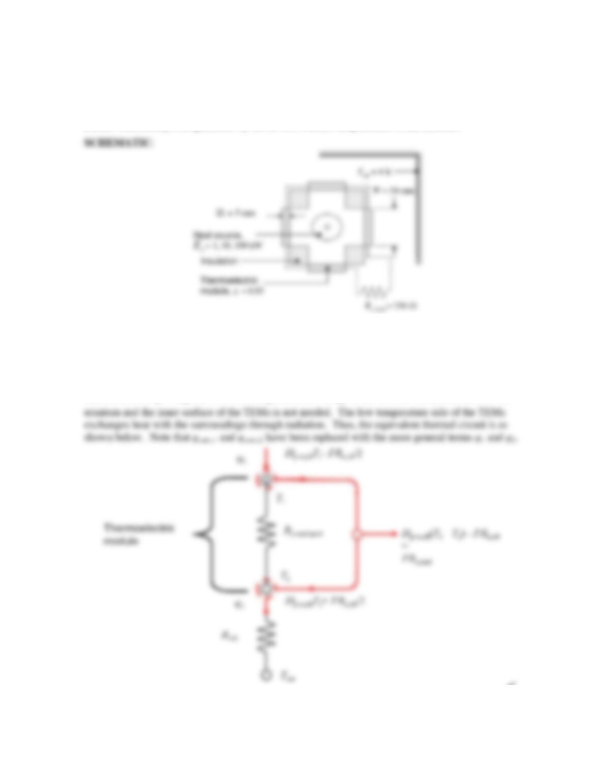
SCHEMATIC:
ASSUMPTIONS: (1) Steady–state, one-dimensional conduction, (2) Constant properties, (3) Large
surroundings.
ANALYSIS: The portion of the equivalent thermal circuit that describes the thermoelectric module is
the same as shown in Figure 3.24b. However, the external thermal resistances are different. The high
temperature side of the TEM is exposed to the stove surface through a contact resistance, Rt,c. The
low temperature side exchanges heat with the surroundings through radiation and convection. Since
<
Continued…
PROBLEM 3.132 (Cont.)
The two external resistances can be calculated as follows:
The radiation heat transfer coefficient, hr, depends on the unknown TEM surface temperature, T2.
This can be left as an unknown in solving the simultaneous equations.
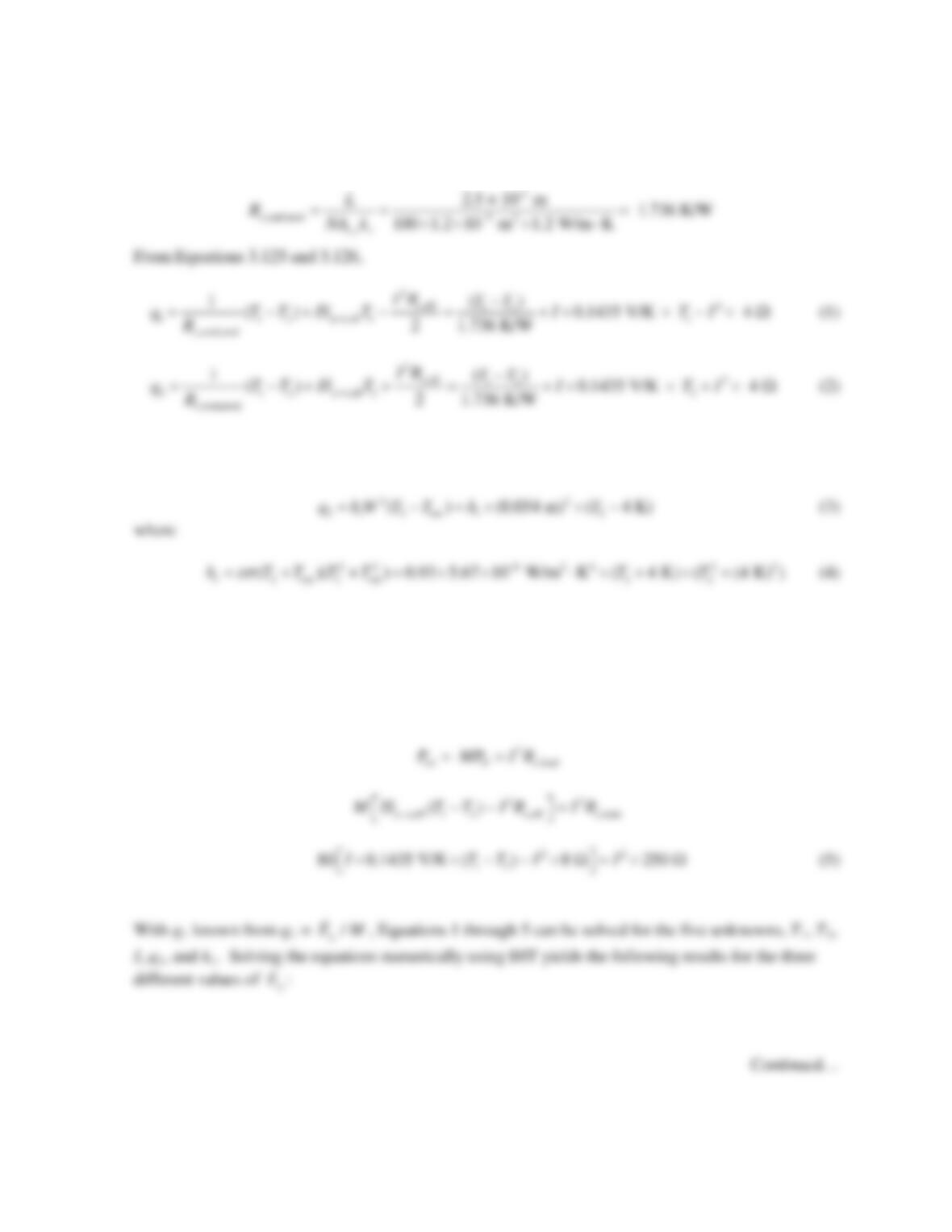
The analysis proceeds as in Example 3.12. The conduction resistance of one module is the same as in
the example, namely
Additional relationships can be written by considering heat transfer through the external resistances.
The electric power produced by the single module, PN, is equal to the electric power dissipated in the load
resistance. Equating the expression for PN from Equation 3.127 to the electric power dissipated in the load
PROBLEM 3.132 (Cont.)
Equations 1 through 6 may be solved simultaneously, for example using IHT, to yield I = 0.27 A, and
PN = I2Re,load = (0.27 A)2 × 3 W = 0.22 W <
COMMENTS: (1) Radiation is significant. If radiation heat transfer were neglected, the electrical
PROBLEM 3.133
KNOWN: Thermal energy generation rate. Dimensions of thermoelectric modules and total number
of modules. Thermoelectric module performance parameters, load electrical resistance, emissivity of
the exposed surface of the thermoelectric modules, deep space temperature.
FIND: Electrical power generated by the device. Surface temperatures of the modules.
ASSUMPTIONS: (1) Steady–state, one-dimensional conduction, (2) Constant properties, (3) Large
surroundings.
ANALYSIS: The portion of the equivalent thermal circuit that describes the thermoelectric module is
the same as shown in Figure 3.24b. The energy generated in the uranium is known, and under steady–
state conditions q1 =
/
g
EM
. As a consequence, knowledge of the thermal resistance between the
<
Continued…
PROBLEM 3.133 (Cont.)
The analysis proceeds as in Example 3.12. The conduction resistance of one module is the same as in
the example, namely
An additional relationship can be written by considering heat transfer by radiation to deep space.
The radiation heat transfer coefficient, hr, depends on the unknown TEM surface temperature, T2.
This can be left as an unknown in solving the simultaneous equations.
The electric power produced by all 80 modules, Ptot, is equal to the electric power dissipated in the
load resistance. Making use of Equation 3.127 and equating the total electrical power generated in the
M modules to the electric power dissipated in the load gives
PROBLEM 3.133 (Cont.)
g
E
(kW)
I (A) Ptot (W) T2 (K)
η
= P
N
/q
1
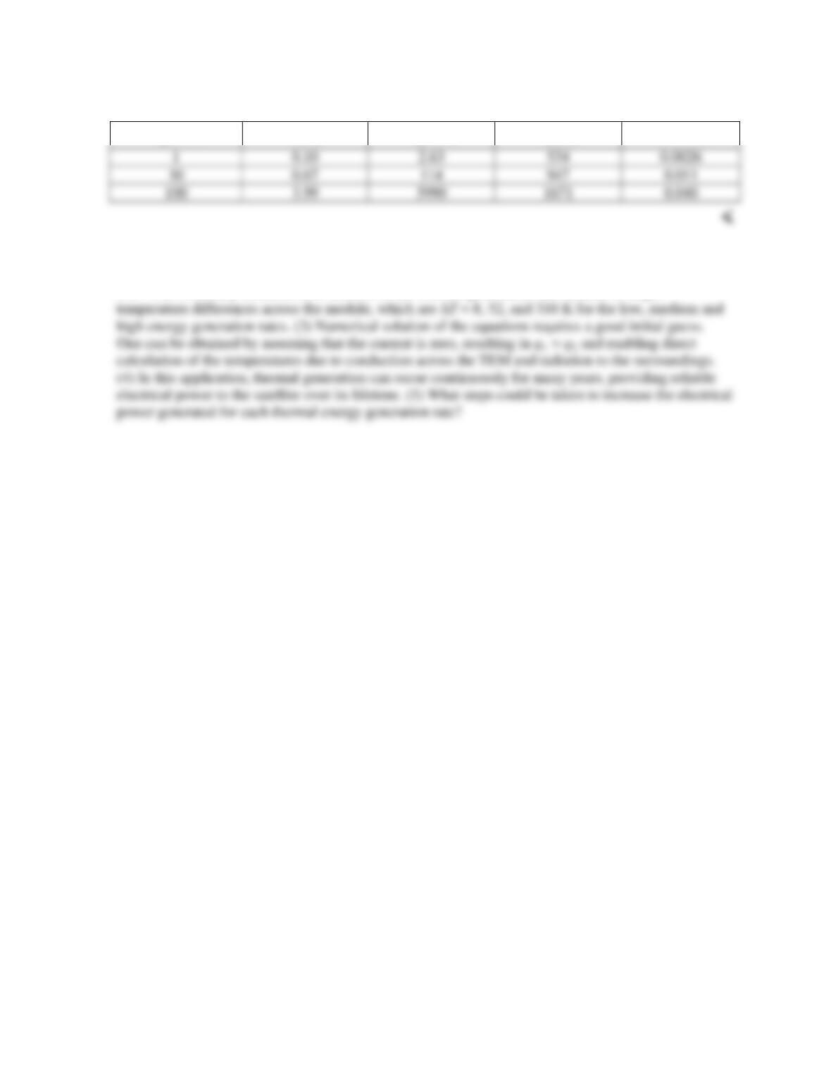
COMMENTS: (1) The temperature for the highest thermal energy generation rate is unacceptably
high. (2) The electrical energy generated by the device is relatively high, but the efficiency is quite
low. The efficiency increases as a function of the thermal generation rate because of larger
PROBLEM 3.134
KNOWN: Net radiation heat flux on absorber plate. Dimensions of thermoelectric modules, total
number of modules, spacing of module rows. Thermoelectric module performance parameters, load
electrical resistance. Water temperature and heat transfer coefficient.
FIND: Electrical power produced by one row of thermoelectric modules. Heat transfer rate to water.
SCHEMATIC:
Cover
ASSUMPTIONS: (1) Steady–state conditions, (2) Constant properties, (3) Negligible losses through
insulation, (4) Negligible losses by convection at absorber plate surface, (5) High thermal conductivity
tube wall creates uniform temperature around the tube perimeter, (6) Tubes of square cross section. (7)
Water temperature remains at 40°C.
ANALYSIS: The heat absorbed in the absorber plate is known, and under steady-state conditions all
of this heat must conduct along the absorber plate and enter the thermoelectric modules, so that the
heat associated with one module is given by
Continued…
PROBLEM 3.134 (Cont.)
The analysis proceeds as in Example 3.12. The conduction resistance of one module is the same as in
the example, namely
An additional relationship can be written by considering heat transfer by convection to the water. It is
assumed that heat exiting the thermoelectric modules conducts around the perimeter of the square tube
wall and enters the water uniformly over the entire tube wall area,
The electric power produced by all M = 20 modules, Ptot, is equal to the electric power dissipated in
the load resistance. Making use of Equation 3.127, and equating the total electrical power generated in
the M modules to the electric power dissipated in the load gives
COMMENTS: (1) This technology provides combined hot water and electricity generation and could
potentially displace photovoltaics. If hot water is stored in a thermal energy storage unit, it can be
used to generate electricity 24 hours per day, exploiting nighttime radiation loss to the cold sky. (2)
The heat entering the water will cause the water temperature to increase along a row of modules. This
would have to be accounted for in a more accurate analysis. (3) The electrical conversion efficiency is
PROBLEM 3.135
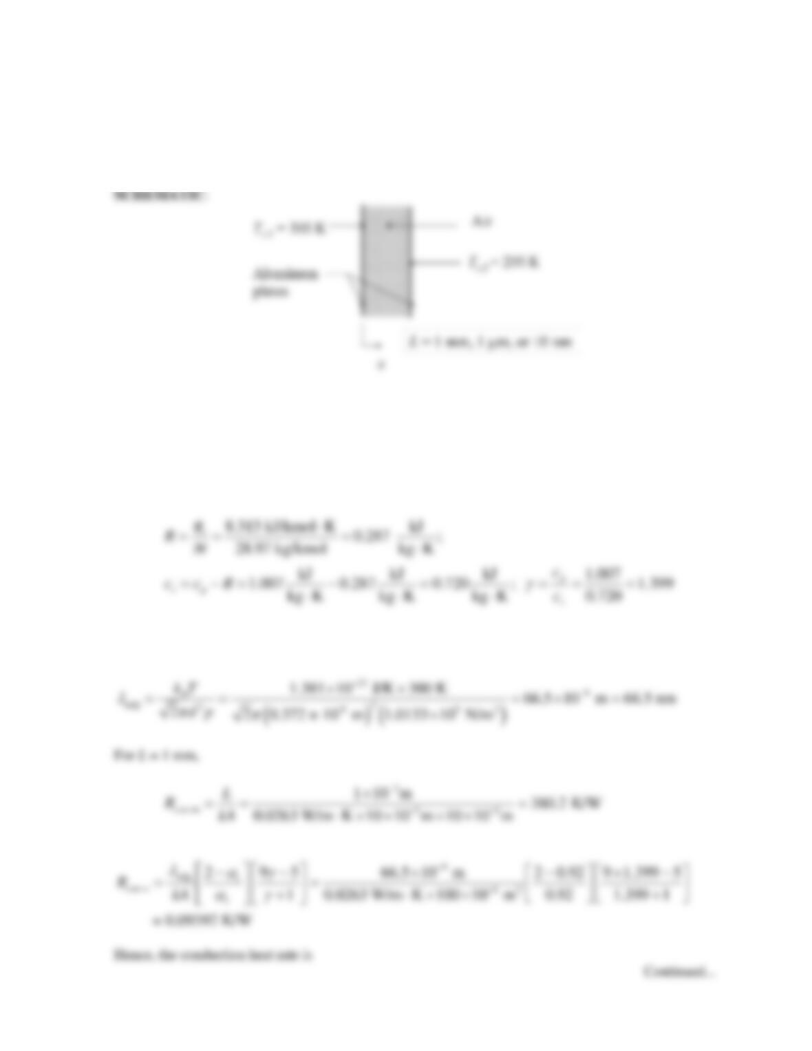
KNOWN: Size and temperatures of parallel aluminum plates. Spacing between the plates. Air
between the plates.
FIND: The conduction heat transfer rate through the air.
ASSUMPTIONS: (1) Ideal gas behavior.
PROPERTIES: Table A.4 (T = 300 K): Air; cp = 1007 J/kg⋅K, k = 0.0263 W/m∙K. Figure 2.8: Air; M
= 28.97 kg/kmol, d = 0.372 × 10⁻⁹ m.
ANALYSIS: For air, the ideal gas constant, specific heat at constant volume, and ratio of specific
heats are:
From Equation 2.11 the mean free path of air is
PROBLEM 3.135 (Cont.)
Hence, the conduction heat rate is
For L = 10 nm,
Hence, the conduction heat rate is
COMMENT: If the molecule-surface collision resistance were to be neglected, the heat rates would
be q = 0.0263 W, 26.3 W, and 2632 W for the L = 1 mm, 1 mm and 10 nm plate spacings, respectively.
Hence, molecule–surface collisions are negligible for large plate spacings, and dominant at small plate
spacings.
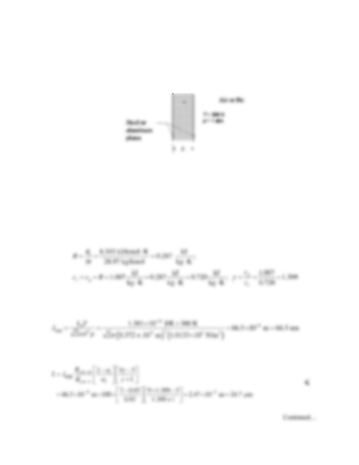
PROBLEM 3.136
KNOWN: Air or helium between steel and aluminum parallel plates, respectively. Gas temperature
and pressure. Thermal accommodation coefficient values.
FIND: The separation distance, L, above which Rt,m-s/Rt,m-m is less than 0.01 for (a) air and (b) helium.
SCHEMATIC:
ASSUMPTIONS: (1) Ideal gas behavior, (2) One-dimensional conduction.
PROPERTIES: Table A.4 (T = 300 K): Air; cp = 1007 J/kg⋅K, k = 0.0263 W/m∙K. He; cp = 5193
J/kg⋅K, k = 0.170 W/m∙K Figure 2.8: Air; M = 28.97 kg/kmol, d = 0.372 × 10⁻⁹ m. He; M = 4.003
kg/kmol, d = 0.219 × 10⁻⁹ m.
ANALYSIS:
(i) For air, the ideal gas constant, specific heat at constant volume, and ratio of specific heats are:
From Equation 2.11 the mean free path of air is
From Section 3.7.3 the plate separation, L, is