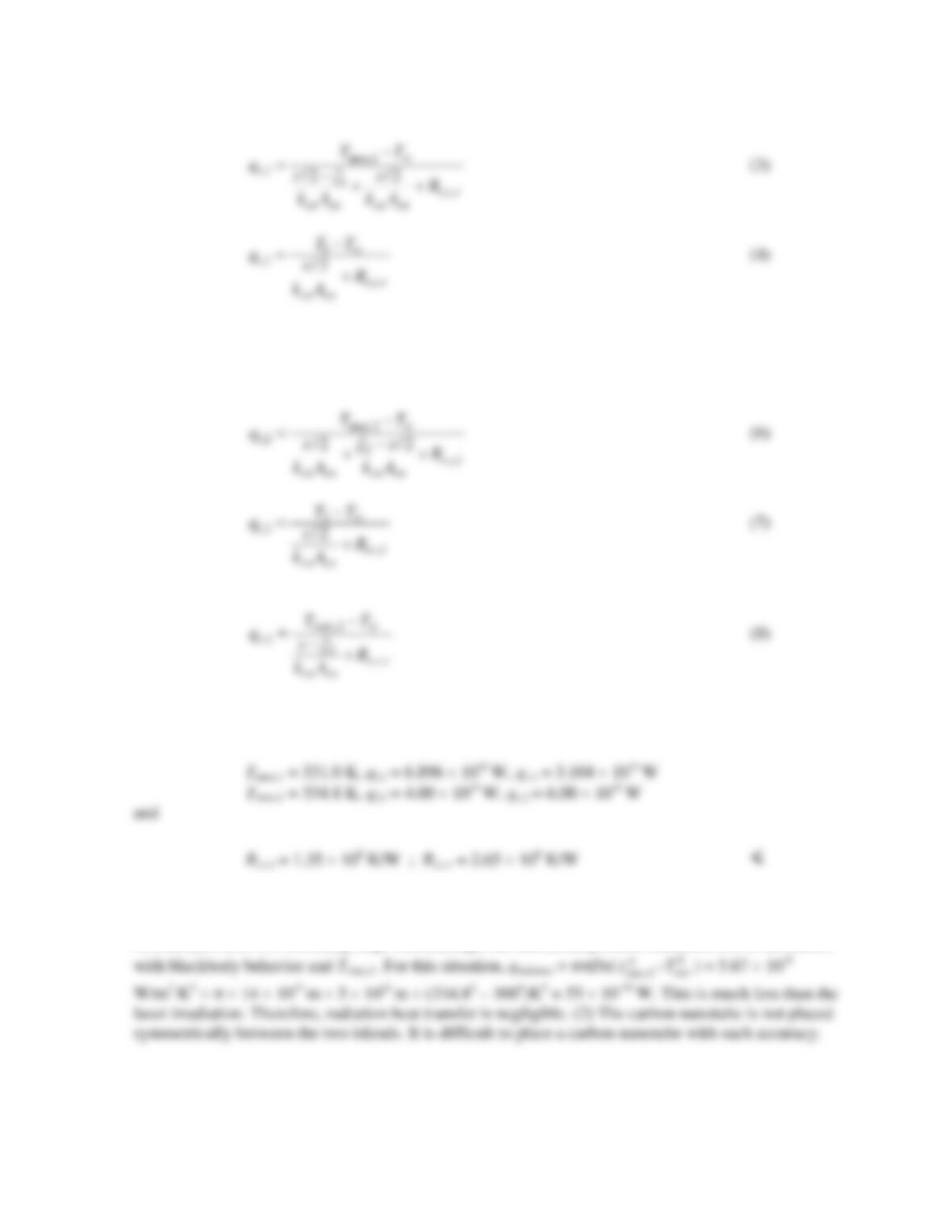
PROBLEM 3.96 (Cont.)
For irradiation of the right side of the nanotube (bottom circuit),
,2 ,2lr
qq q= +
(5)
With kcn = 3100 W/m⋅K, Acn = 1.54 × 10⁻¹⁶ m2,
ξ
1 = 1.5 µm, T1 = 324.5 K, ξ2 = 3.5 µm, and T2 =
326.4 K, Equations (1) through (8) may be solved simultaneously to yield
COMMENTS: (1) Assuming large surroundings, the maximum possible radiation loss is associated
PROBLEM 3.97
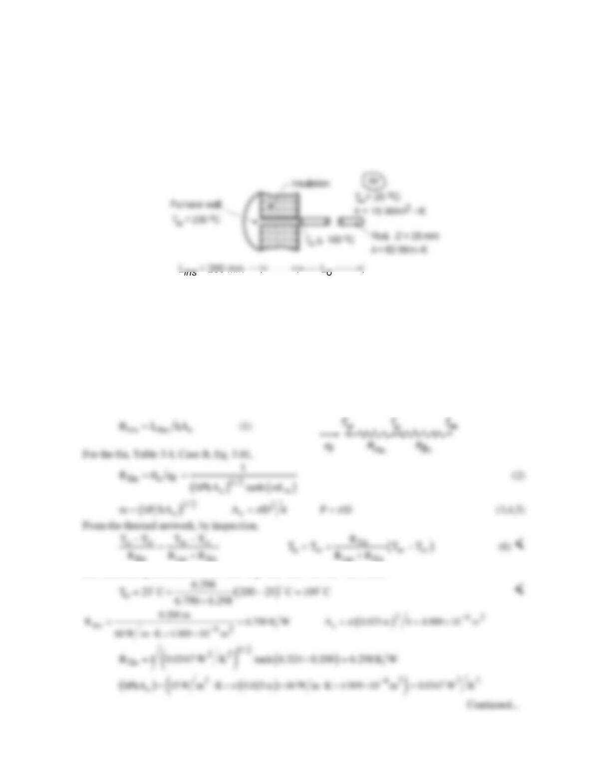
KNOWN: Rod protruding normally from a furnace wall covered with insulation of thickness Lins
with the length Lo exposed to convection with ambient air.
FIND: (a) An expression for the exposed surface temperature To as a function of the prescribed
thermal and geometrical parameters. (b) Will a rod of Lo = 100 mm meet the specified operating
limit, T0 ≤ 100°C? If not, what design parameters would you change?
SCHEMATIC:
ASSUMPTIONS: (1) Steady-state conditions, (2) One-dimensional conduction in rod, (3) Negligible
thermal contact resistance between the rod and hot furnace wall, (4) Insulated section of rod, Lins ,
experiences no lateral heat losses, (5) Convection coefficient uniform over the exposed portion of the
rod, Lo, (6) Adiabatic tip condition for the rod and (7) Negligible radiation exchange between rod
and its surroundings.
ANALYSIS: (a) The rod can be modeled as a thermal network comprised of two resistances in
series: the portion of the rod, Lins , covered by insulation, Rins , and the portion of the rod, Lo,
experiencing convection, and behaving as a fin with an adiabatic tip condition, Rfin . For the insulated
section:
fin ins fin ins fin
(b) Substituting numerical values into Eqs. (1) – (6) with Lo = 200 mm,
PROBLEM 3.97 (Cont.)
( ) ( )
( )
1/ 2
2 42 1
1/ 2
c
m hP kA 15 W m K 0.025 m 60 W m K 4.909 10 m 6.324 m
π
−−
= = ⋅× ⋅× × =
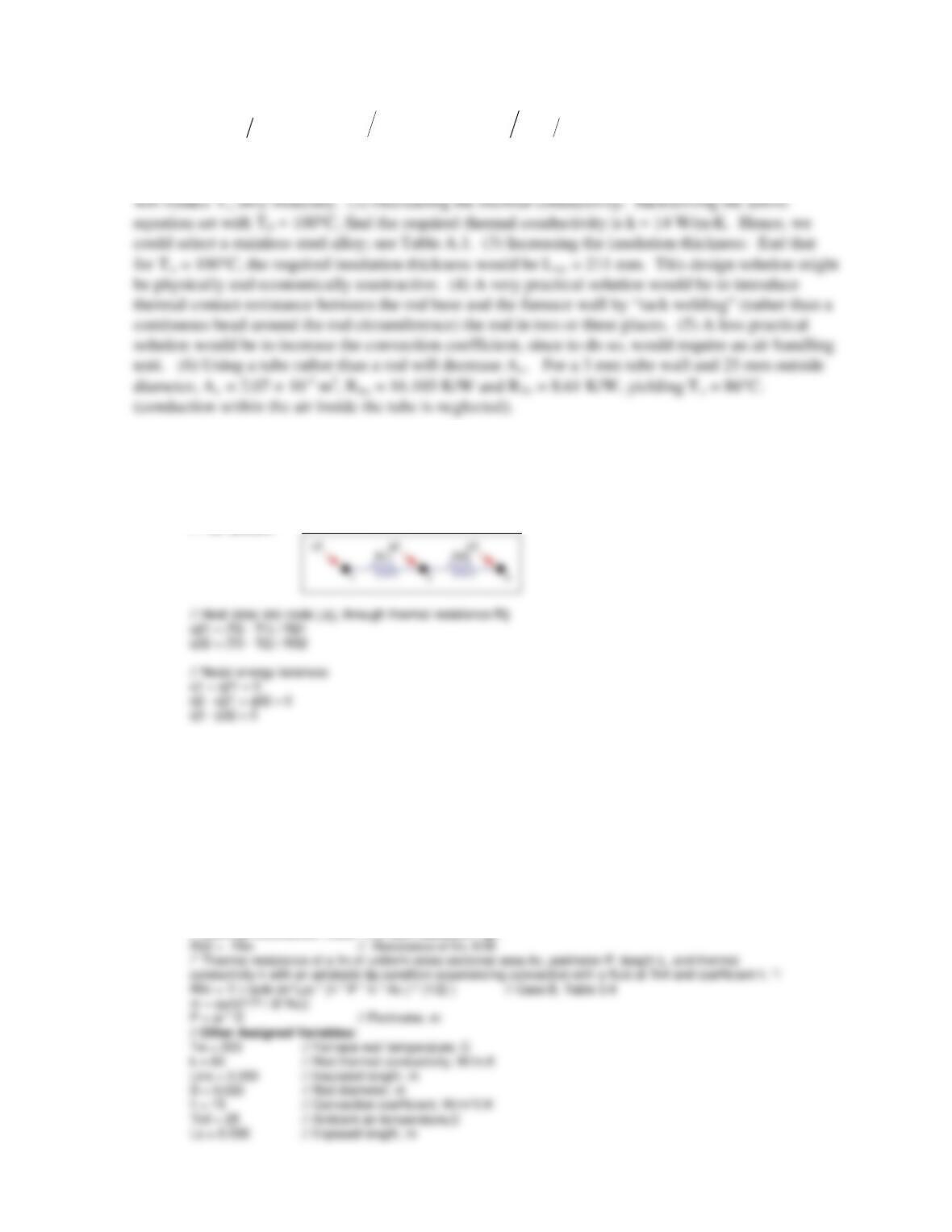
Consider the following design changes aimed at reducing To ≤ 100°C. (1) Increasing length of the fin
portions: with Lo = 400 and 600 mm, To is 102.8°C and 102.3°C, respectively. Hence, increasing Lo
COMMENTS: (1) Would replacing the rod by a thick-walled tube provide a practical solution?
(2) The IHT Thermal Resistance Network Model and the Thermal Resistance Tool for a fin with an
adiabatic tip were used to create a model of the rod. The Workspace is shown below.
// Thermal Resistance Network Model:
// The Network:
/* Assigned variables list: deselect the qi, Rij and Ti which are unknowns; set qi = 0 for embedded nodal
points at which there is no external source of heat. */
T1 = Tw // Furnace wall temperature, C
//q1 = // Heat rate, W
T2 = To // To, beginning of rod exposed length
q2 = 0 // Heat rate, W; node 2; no external heat source
T3 = Tinf // Ambient air temperature, C
//q3 = // Heat rate, W
// Thermal Resistances:
// Rod – conduction resistance
R21 = Lins / (k * Ac) // Conduction resistance, K/W
Ac = pi * D^2 / 4 // Cross sectional area of rod, m^2
// Thermal Resistance Tools – Fin with Adiabatic Tip:
PROBLEM 3.98
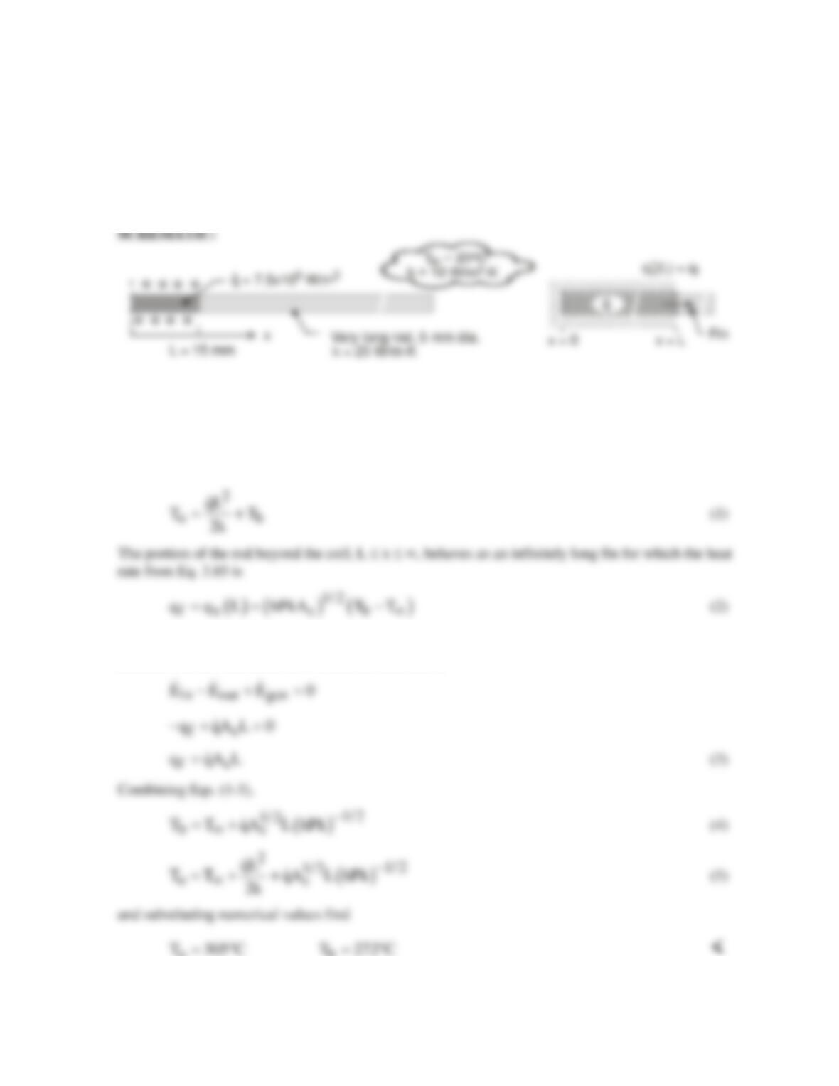
KNOWN: Very long rod (D, k) subjected to induction heating experiences uniform volumetric
generation
( )
q
over the center, 30-mm long portion. The unheated portions experience convection
(T∞, h).
FIND: Calculate the temperature of the rod at the mid-point of the heated portion within the coil, To,
and at the edge of the heated portion, Tb.
ASSUMPTIONS: (1) Steady-state conditions, (2) One-dimensional conduction with uniform
q
in
portion of rod within the coil; no convection from lateral surface of rod, (3) Exposed portions of rod
behave as infinitely long fins, and (4) Constant properties, (5) Neglect radiation.
ANALYSIS: (a) and (b) The portion of the rod within the coil, 0 ≤ x ≤ + L, experiences one-
dimensional conduction with uniform generation. From Eq. 3.48,
where P = πD and Ac = πD2/4. From an overall energy balance on the imbedded portion of the rod as
illustrated in the schematic above, find the heat rate as
ob
COMMENT: Assuming
0.8ε=
and Tsur = T∞ = 20°C, hrad = 14.6 W/m2·K. Hence, radiation is
significant and would serve to substantially reduce both To and Tb.
PROBLEM 3.99
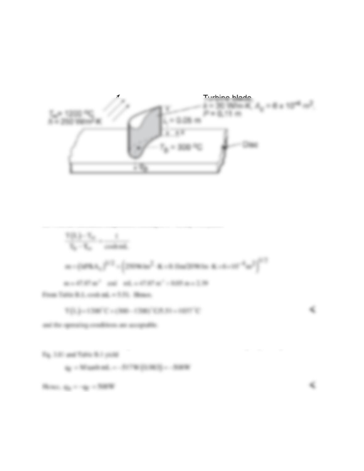
KNOWN: Dimensions and thermal conductivity of a gas turbine blade. Temperature and convection
coefficient of gas stream. Temperature of blade base and maximum allowable blade temperature.
FIND: (a) Whether blade operating conditions are acceptable, (b) Heat transfer to blade coolant.
SCHEMATIC:
ASSUMPTIONS: (1) One-dimensional, steady-state conduction in blade, (2) Constant k, (3) Adiabatic
blade tip, (4) Negligible radiation.
ANALYSIS: Conditions in the blade are determined by Case B of Table 3.4.
(a) With the maximum temperature existing at x = L, Eq. 3.80 yields
(b) With
( )
( ) ( )
1/ 2
2 42
1/ 2
cb
M hPkA 250W/m K 0.11m 20W/m K 6 10 m 900 C 517W
−
= Θ= ⋅× × ⋅×× − =−
,
COMMENTS: Radiation losses from the blade surface and convection from the tip will contribute to
reducing the blade temperatures.
PROBLEM 3.100
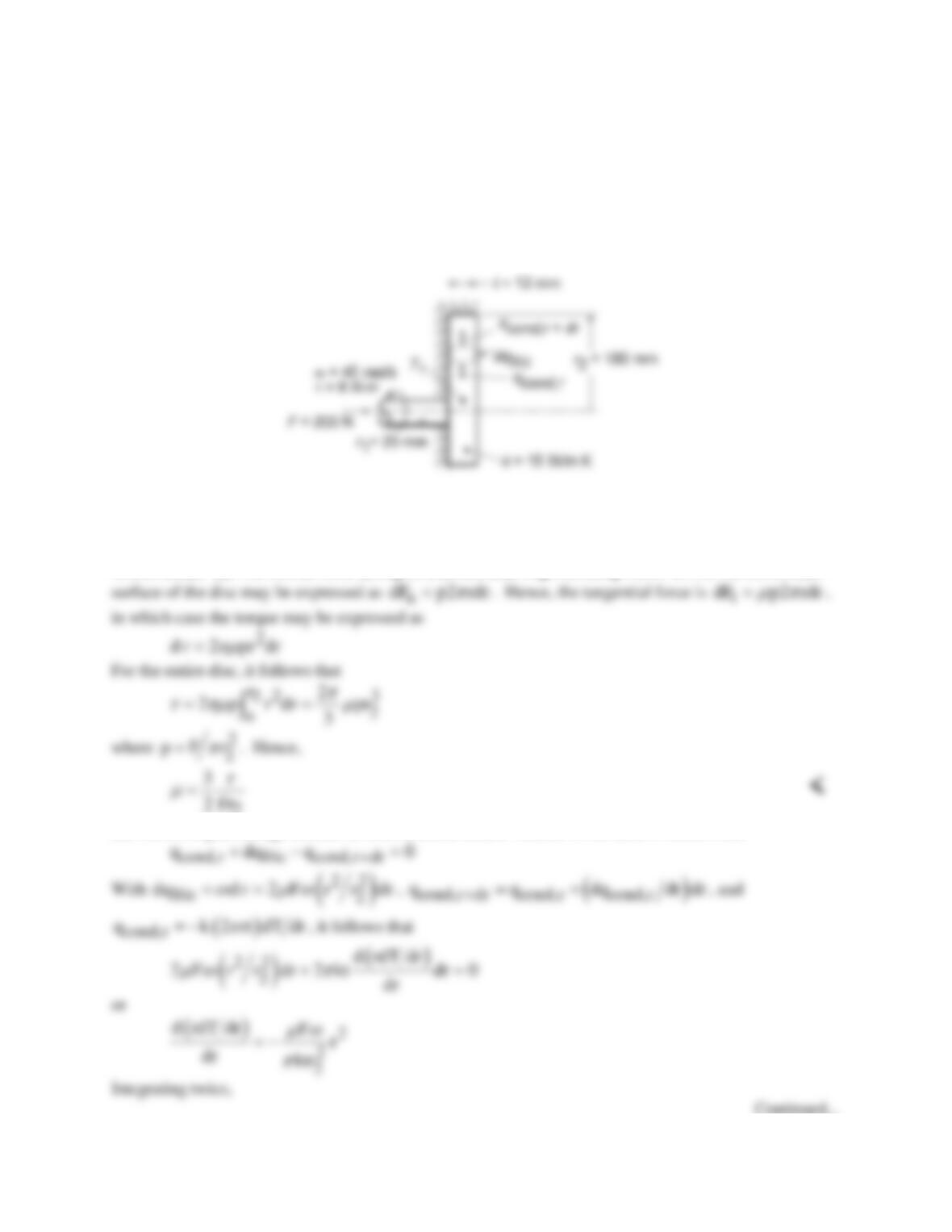
KNOWN: Dimensions of disc/shaft assembly. Applied angular velocity, force, and torque. Thermal
conductivity and inner temperature of disc.
FIND: (a) Expression for the friction coefficient µ, (b) Radial temperature distribution in disc, (c) Value
of µ for prescribed conditions.
SCHEMATIC:
ASSUMPTIONS: (1) Steady-state conditions, (2) One-dimensional radial conduction, (3) Constant k,
(4) Uniform disc contact pressure p, (5) All frictional heat dissipation is transferred to shaft from base of
disc.
ANALYSIS: (a) The normal force acting on a differential ring extending from r to r+dr on the contact
2
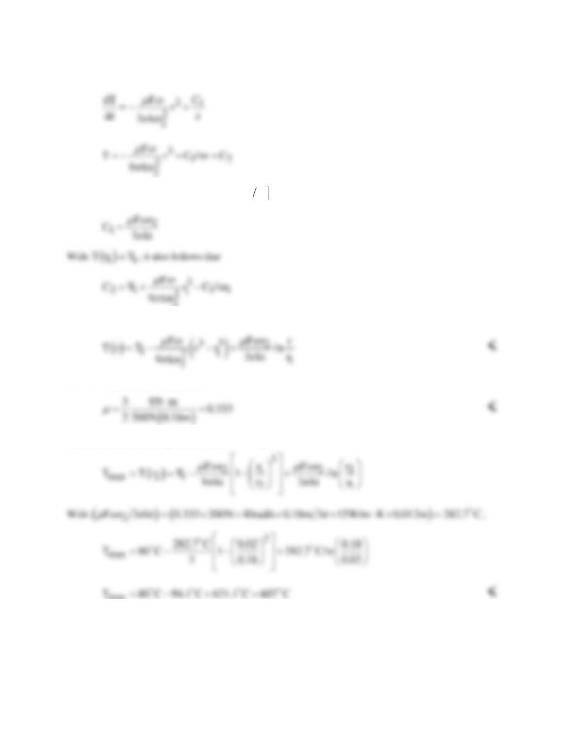
(b) Performing an energy balance on a differential control volume in the disc, it follows that
Continued…
PROBLEM 3.100 (Cont.)
Since the disc is well insulated at
2
2r
r r , dT dr 0= =
and
2
Hence,
(c) For the prescribed conditions,
Since the maximum temperature occurs at r = r2,
max
COMMENTS: The maximum temperature is excessive, and the disks should be actively cooled (by
convection) at their outer surfaces.
PROBLEM 3.101
KNOWN: Extended surface of rectangular cross–section with heat flow in the longitudinal direction.
FIND: Determine the conditions for which the transverse (y–direction) temperature difference is
negligible compared to the temperature difference between the surface and the environment, such that
the 1-D analysis of Section 3.6.1 is valid by finding: (a) An expression for the conduction heat flux at
the surface,
( )
y
q t,
′′
in terms of Ts and To, assuming the transverse temperature distribution is
parabolic, (b) An expression for the convection heat flux at the surface for the x-location; equate the
two expressions, and identify the parameter that determines the ratio (To – Ts)/(Ts – T∞); and (c)
Developing a criterion for the validity of the 1-D assumption used to model an extended surface.
SCHEMATIC:
ASSUMPTIONS: (1) Steady-state conditions, (2) Uniform convection coefficient and (3) Constant
properties.
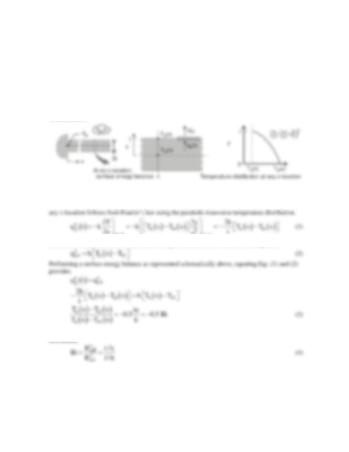
ANALYSIS: (a) Referring to the schematics above, the conduction heat flux at the surface y = t at
yt yt
t
==
(b) The convection heat flux at the surface of any x-location follows from the rate equation
where Bi = ht/k, the Biot number, represents the ratio of the conduction to the convection thermal
(c) The transverse temperature difference (Ts – To) will be negligible compared to the temperature
difference between the surface and the environment (Ts – T∞) when Bi << 1, say, 0.1, an order of
magnitude smaller. This is the criterion to validate the one–dimensional assumption used to model
extended surfaces.
COMMENTS: The coefficient 0.5 in Eq. (3) is a consequence of the parabolic distribution
assumption. This distribution represents the simplest polynomial expression that could approximate
the real distribution.
PROBLEM 3.102
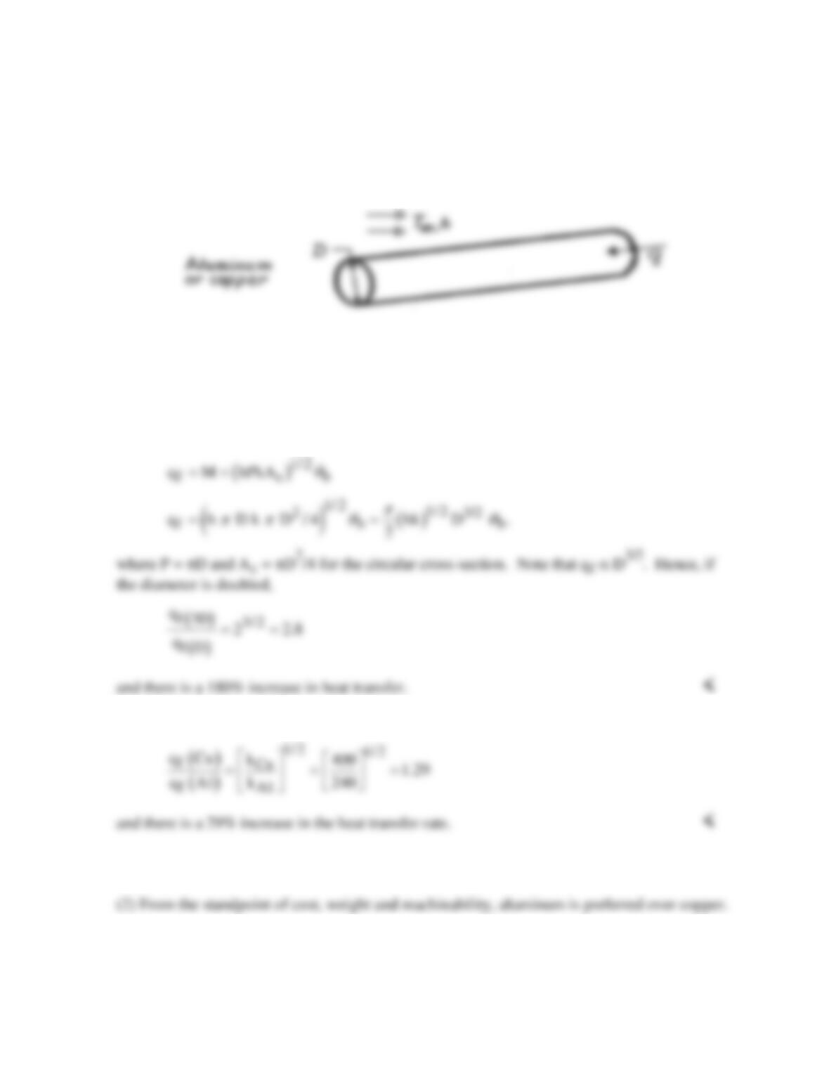
KNOWN: Long, aluminum cylinder acts as an extended surface.
FIND: (a) Increase in heat transfer if diameter is doubled and (b) Increase in heat transfer if
copper is used in place of aluminum.
SCHEMATIC:
ASSUMPTIONS: (1) Steady–state conditions, (2) One-dimensional conduction, (3) Constant
properties, (4) Uniform convection coefficient, (5) Rod is infinitely long.
PROPERTIES: Table A-1, Aluminum (pure): k = 240 W/m⋅K; Table A-1, Copper (pure): k
= 400 W/m⋅K.
ANALYSIS: (a) For an infinitely long fin, the fin heat rate from Table 3.4 is
(b) In changing from aluminum to copper, since qf α k1/2, it follows that
COMMENTS: (1) Because fin effectiveness is enhanced by maximizing P/Ac = 4/D, the use
of a larger number of small diameter fins is preferred to a single large diameter fin.
PROBLEM 3.103
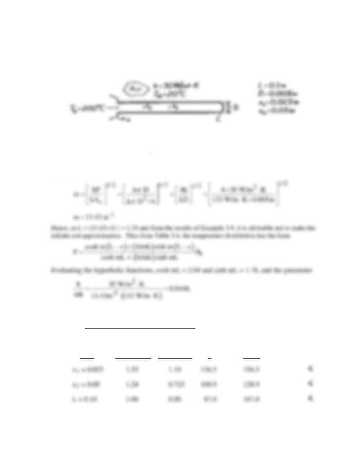
KNOWN: Length, diameter, base temperature and environmental conditions associated with a brass rod.
FIND: Temperature at specified distances along the rod.
SCHEMATIC:
ASSUMPTIONS: (1) Steady–state conditions, (2) One–dimensional conduction, (3) Constant properties, (4)
Negligible radiation, (5) Uniform convection coefficient h.
PROPERTIES: Table A-1, Brass
()
T 110 C : k 133 W/m K.= = ⋅
ANALYSIS: Evaluate first the fin parameter
with θb = 180°C the temperature distribution has the form
( ) ( )
()
cosh m L x 0.0168 sinh m L x 180 C .
2.07
θ
−+ −
=
The temperatures at the prescribed locations are tabulated below.
x(m) cosh m(L-x) sinh m(L–x) θ T(°C)
COMMENTS: If the rod were approximated as infinitely long: T(x1) = 148.7°C, T(x2) =
112.0°C, and T(L) = 67.0°C. The assumption would therefore result in significant
underestimates of the rod temperature.
PROBLEM 3.104
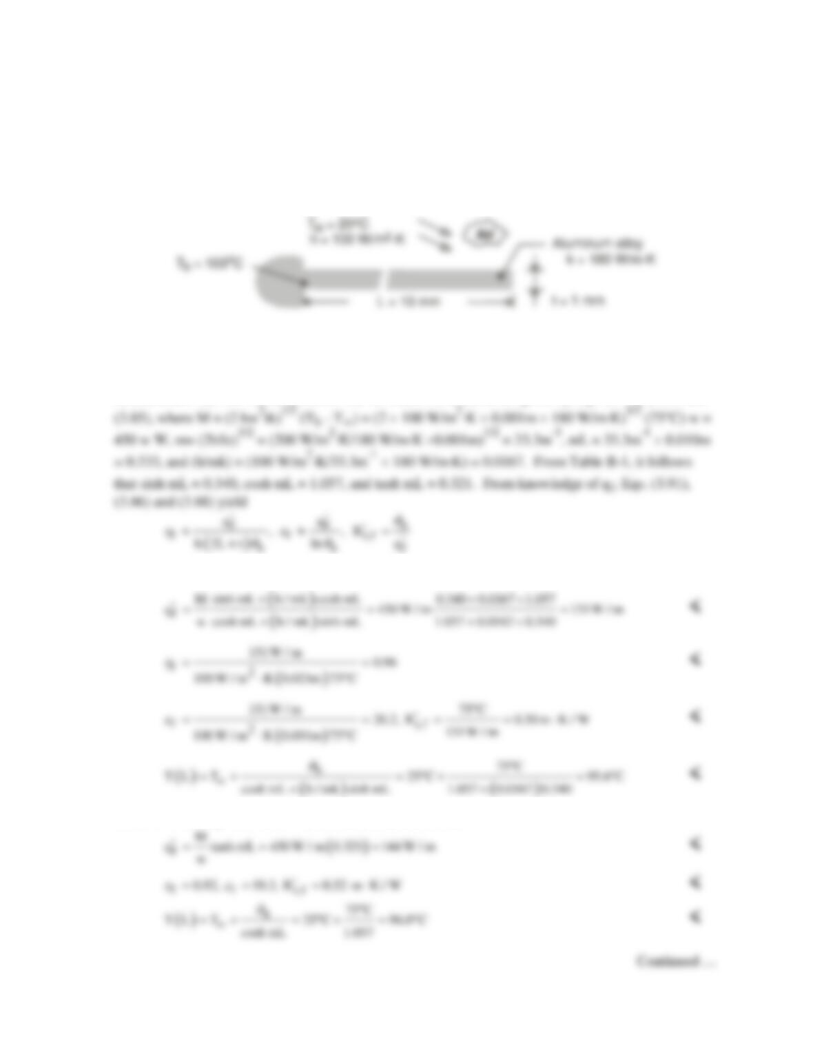
KNOWN: Thickness, length, thermal conductivity, and base temperature of a rectangular fin. Fluid
temperature and convection coefficient.
FIND: (a) Heat rate per unit width, efficiency, effectiveness, thermal resistance, and tip temperature
for different tip conditions, (b) Effect of convection coefficient and thermal conductivity on the heat
rate.
SCHEMATIC:
ASSUMPTIONS: (1) Steady-state, (2) One-dimensional conduction along fin, (3) Constant
properties, (4) Negligible radiation, (5) Uniform convection coefficient, (6) Fin width is much longer
than thickness (w >> t).
ANALYSIS: (a) The fin heat transfer rate for Cases A, B and D are given by Eqs. (3.77), (3.81) and
Case A: From Eq. (3.77), (3.91), (3.86), (3.88) and (3.75),
Case B: From Eqs. (3.81), (3.91), (3.86), (3.88) and (3.80)
PROBLEM 3.104 (Cont.)
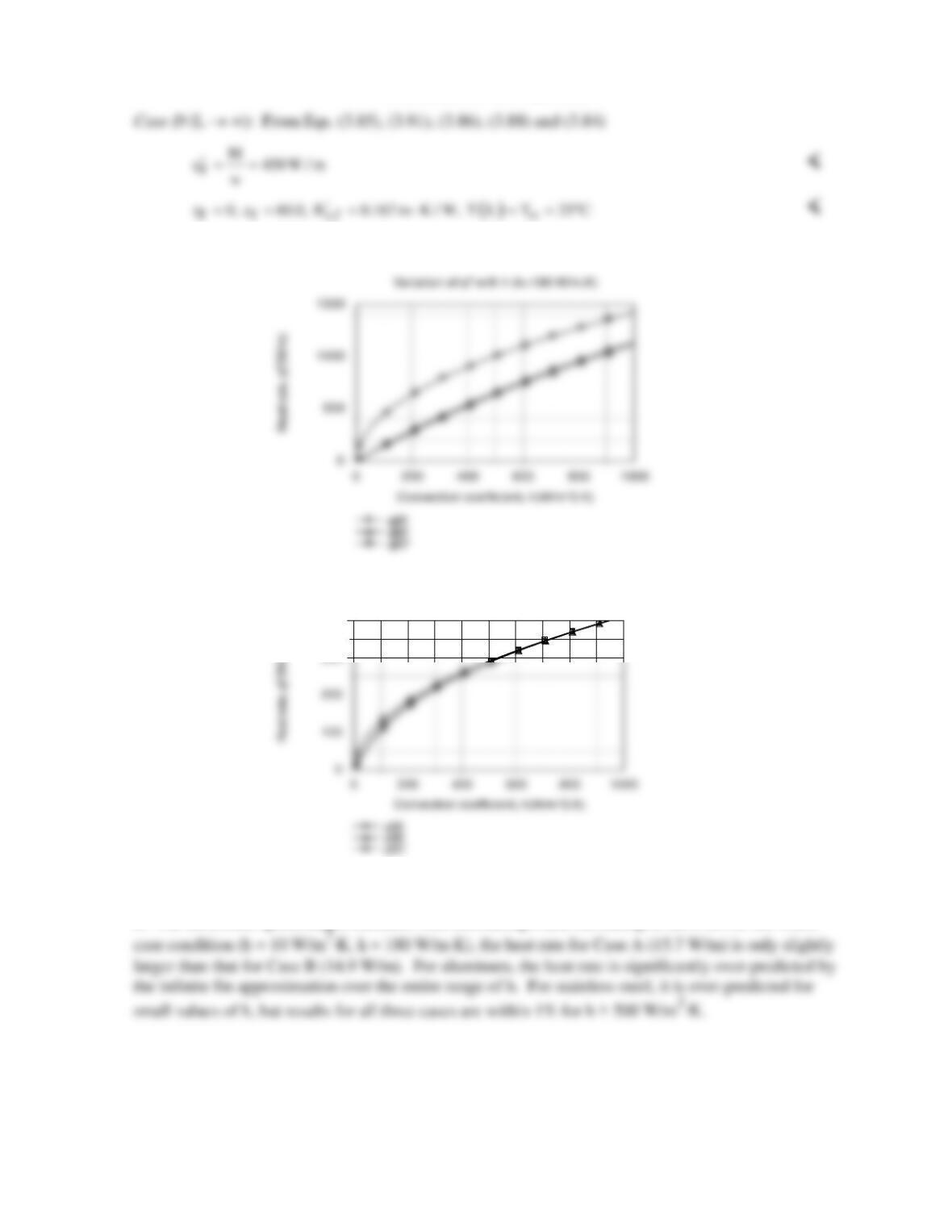
(b) The effect of h on the heat rate is shown below for the aluminum and stainless steel fins.
For both materials, there is little difference between the Case A and B results over the entire range of
h. The difference (percentage) increases with decreasing h and increasing k, but even for the worst
COMMENTS: From the results of Part (a), we see there is a slight reduction in performance
(smaller values of
ff f
q , and ,
hε
′
as well as a larger value of
t,f
R)
′
associated with insulating the tip.
Although hf = 0 for the infinite fin,
f
q′
and εf are substantially larger than results for L = 10 mm,
indicating that performance may be significantly improved by increasing L.
Variation of qf‘ with h (k=15W/m.K)
300
400
PROBLEM 3.105
KNOWN: Thermal conductivity and diameter of a pin fin. Value of the heat transfer coefficient and
fin efficiency.
FIND: (a) Length of fin, (b) Fin effectiveness.
SCHEMATIC:
ASSUMPTIONS: (1) Steady–state, one-dimensional conditions, (2) Negligible radiation heat
transfer, (3) Constant properties, (4) Convection from fin tip.
PROPERTIES: Given, Aluminum Alloy: k = 160 W/m⋅K.
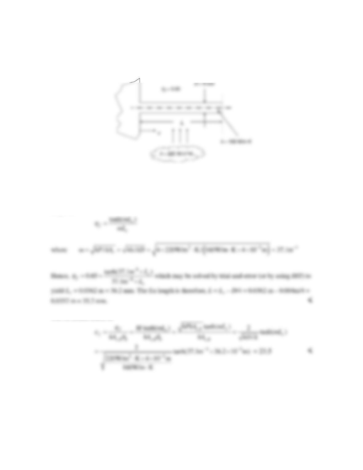
ANALYSIS: For an active fin tip, the efficiency may be expressed in terms of the corrected fin
length as:
The fin effectiveness is:
COMMENTS: The values of the fin effectiveness and fin efficiency are independent of the base or
fluid temperatures.
PROBLEM 3.106
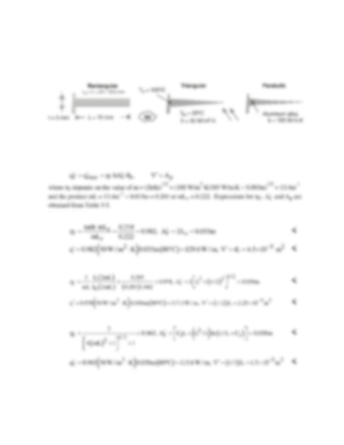
KNOWN: Length, thickness and temperature of straight fins of rectangular, triangular and parabolic
profiles. Ambient air temperature and convection coefficient.
FIND: Heat rate per unit width, efficiency and volume of each fin.
SCHEMATIC:
ASSUMPTIONS: (1) Steady-state, (2) One-dimensional conduction, (3) Constant properties, (4)
Negligible radiation, (5) Uniform convection coefficient.
ANALYSIS: For each fin,
Rectangular Fin:
Triangular Fin:
Parabolic Fin:
COMMENTS: Although the heat rate is slightly larger (~10%) for the rectangular fin than for the
triangular or parabolic fins, the heat rate per unit volume (or mass) is larger and largest for the
triangular and parabolic fins, respectively.
PROBLEM 3.107
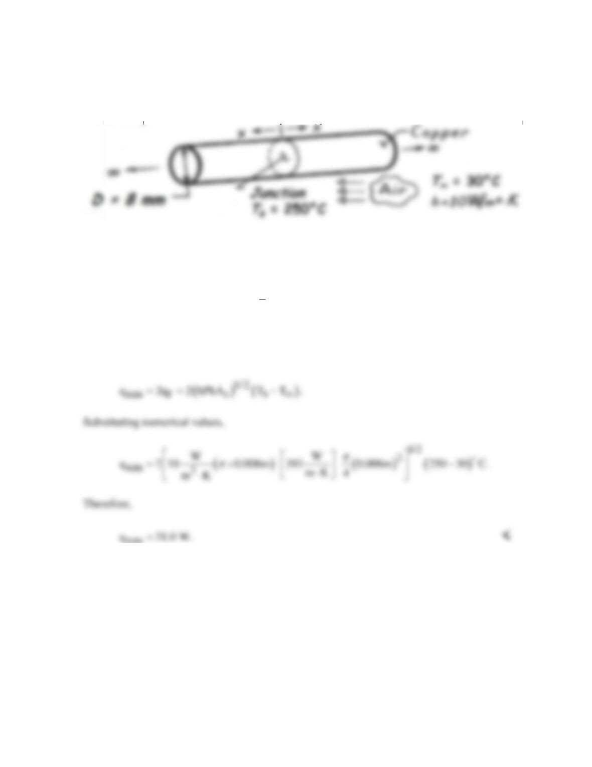
KNOWN: Melting point of solder used to join two long copper rods.
FIND: Minimum power needed to solder the rods.
SCHEMATIC:
ASSUMPTIONS: (1) Steady-state conditions, (2) One-dimensional conduction along the
rods, (3) Constant properties, (4) No internal heat generation, (5) Negligible radiation
exchange with surroundings, (6) Uniform h, and (7) Infinitely long rods.
PROPERTIES: Table A-1: Copper
( )
T 250 30 / 2 C 400K: k 393 W/m K.=+ ≈= ⋅
ANALYSIS: The junction must be maintained at 250°C while energy is transferred by
conduction from the junction (along both rods). The minimum power is twice the fin heat rate
for an infinitely long fin,
min
COMMENTS: Radiation losses from the rods may be significant, particularly near the
junction, thereby requiring a larger power input to maintain the junction at 250°C.
PROBLEM 3.108
KNOWN: Dimensions and end temperatures of pin fins.
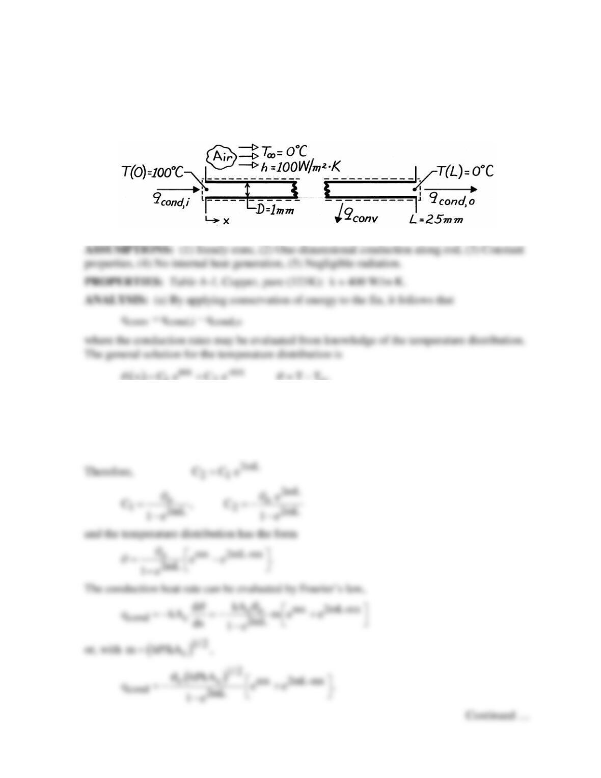
FIND: (a) Heat transfer by convection from a single fin and (b) Total heat transfer from a 1
m2 surface with fins mounted on 4mm centers.
SCHEMATIC:
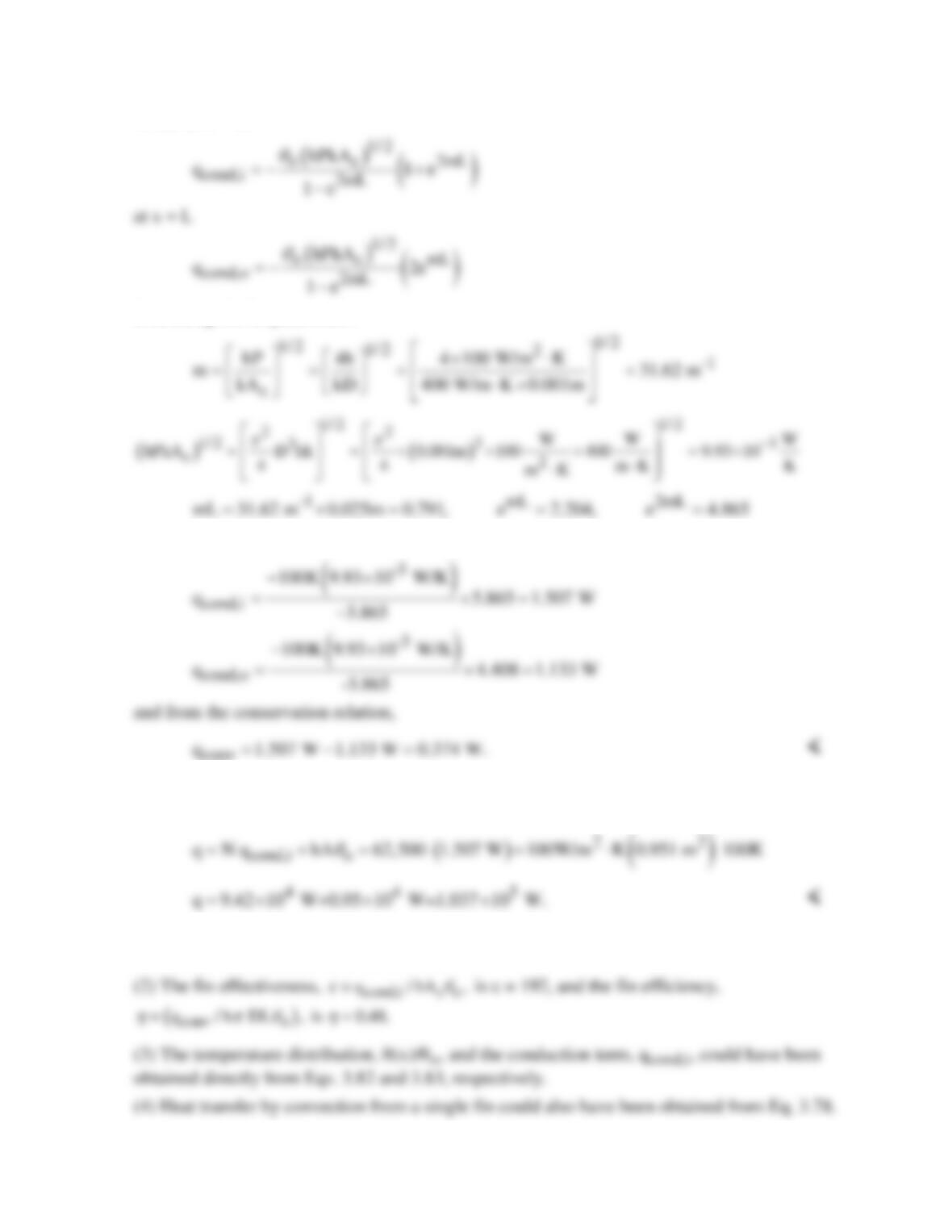
( )
12
∞
The boundary conditions are θ(0) ≡ θo = 100°C and θ(L) = 0. Hence
o12
CC
θ
= +
mL -mL
12
0 C e C e= +
PROBLEM 3.108 (Cont.)
Hence at x = 0,
Evaluating the fin parameters:
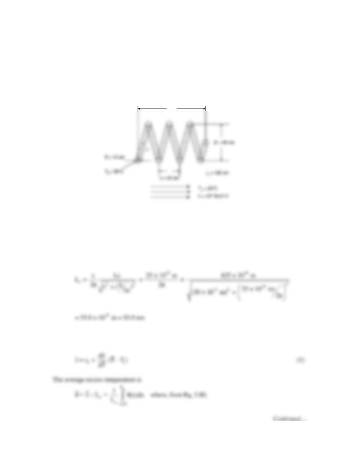
The conduction heat rates are
conv
(b) The total heat transfer rate is the heat transfer from N = 250×250 = 62,500 rods and the
heat transfer from the remaining (bare) surface (A = 1m2 – NAc). Hence,
COMMENTS: (1) The fins, which cover only 5% of the surface area, provide for more than
90% of the heat transfer from the surface.
PROBLEM 3.109
KNOWN: Dimensions of a nanospring, dependence of pitch upon temperature.
FIND: Actuation distance of the spring in response to heating of its end, accuracy to which the
actuation length can be controlled.
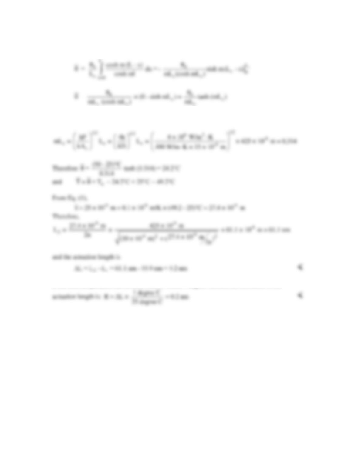
SCHEMATIC:
L
L
ASSUMPTIONS: (1) Constant properties, (2) Steady-state conditions, (3) One-dimensional heat
transfer, (4) Adiabatic tip, (5) Negligible radiation heat transfer, (6) Negligible impact of
nanoscale heat transfer effects.
PROPERTIES: Table A.2, silicon carbide (300 K): k = 490 W/m⋅K.
ANALYSIS: When the nanospring is at Ti = 25°C, the spring length is
Since the average spring pitch varies linearly with the average temperature, the average pitch of
the heated spring is
PROBLEM 3.109 (Cont.)
For a particular spring,
If the base temperature can be controlled to within 1 degree Celsius, the resolution of the
COMMENTS: (1) The actuation distance and its resolution are extremely small. (2) Application
of other tip conditions will lead to different predictions of the actuation distance.
PROBLEM 3.110
KNOWN: Diameter and length of an aluminum pin fin. Base and ambient temperatures, value of
the convection heat transfer coefficient.
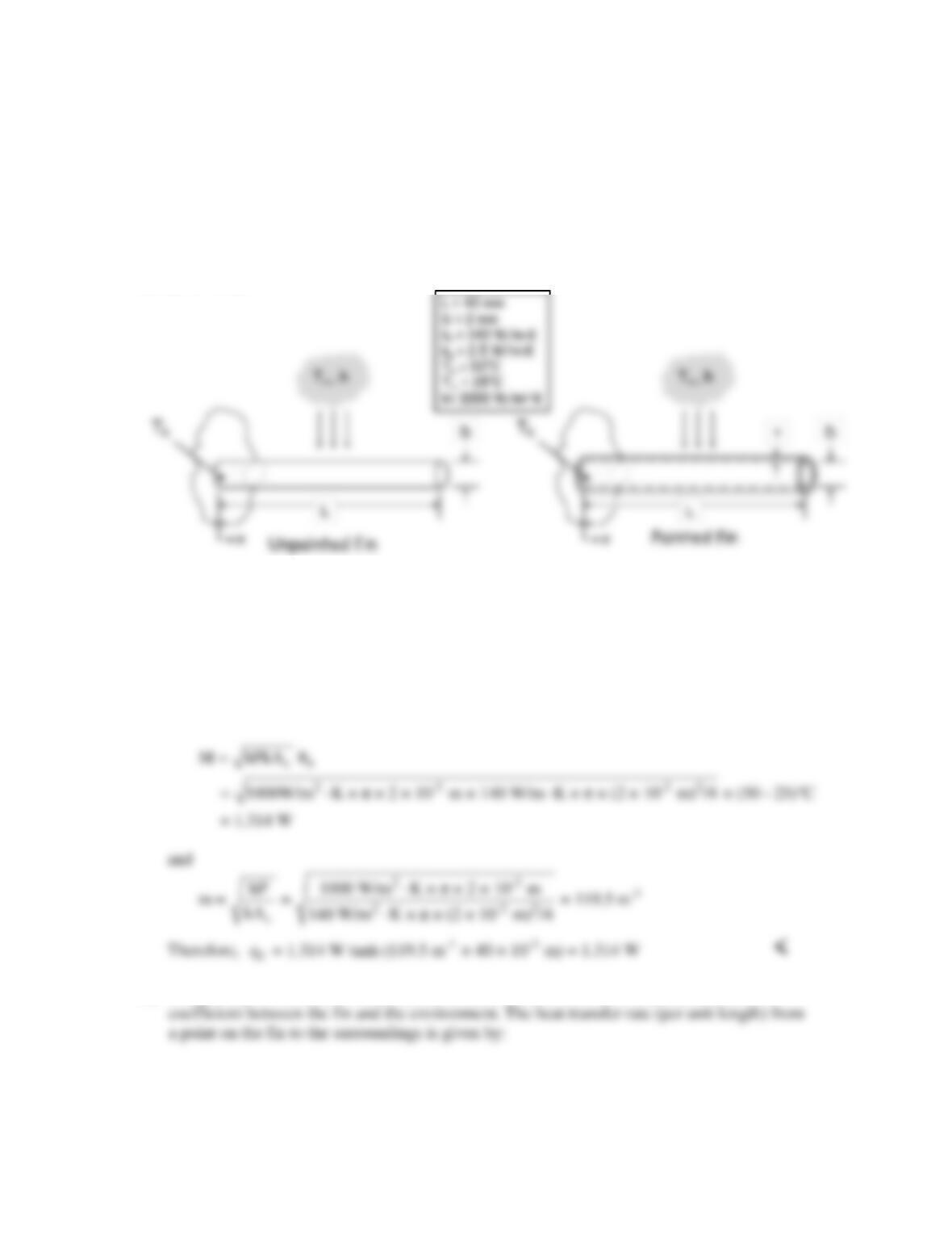
FIND: (a) Fin heat transfer rate with an adiabatic tip, (b) Thickness of paint needed to maximize
fin heat transfer rate. Compare heat transfer rate with and without paint.
SCHEMATIC:
ASSUMPTIONS: (1) Constant properties, (2) Steady–state conditions, (3) Temperature nearly
uniform across fin cross section, (4) Negligible radiation heat transfer, (5) Negligible heat
conduction along paint layer, (6) Negligible contact resistance.
PROPERTIES: Given, kf = 140 W/m∙K, kp = 2.5 W/m∙K.
ANALYSIS:
(a) The fin heat transfer rate is given by Eq. 3.81; qf = M tanh mL, where
(b) The paint can be treated as a thermal resistance that modifies the overall heat transfer
Continued…