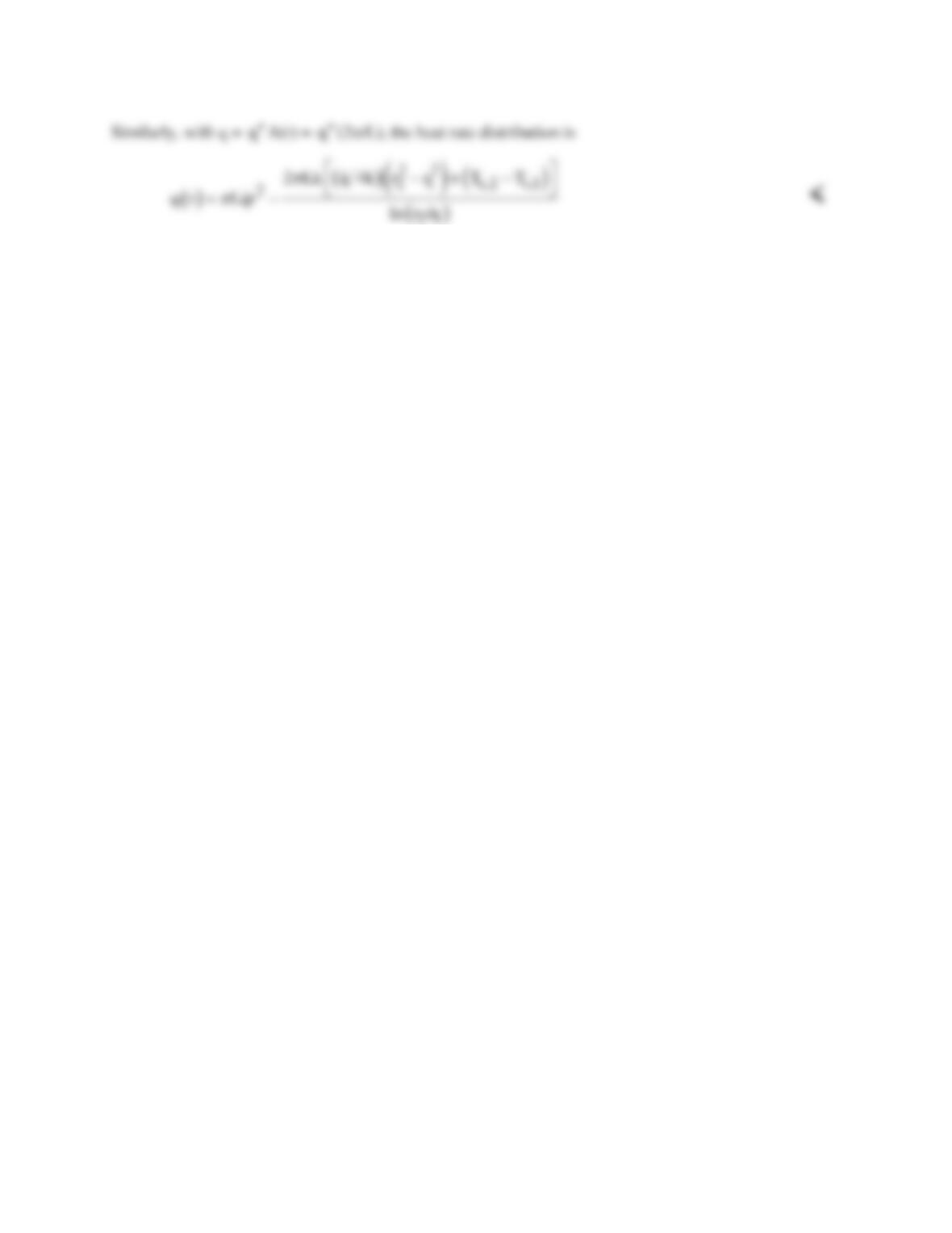
PROBLEM 3.71 (Cont.)
COMMENT: An overall energy balance on the cylindrical shell can be expressed as
( )
qr
21
q(r ) =−
()
22
Lq qV
21
rr
π
−=
where V is the volume of the shell. Thus, the energy balance expresses that the net
rate at which energy leaves the shell is equal to the rate of energy generated within the shell.
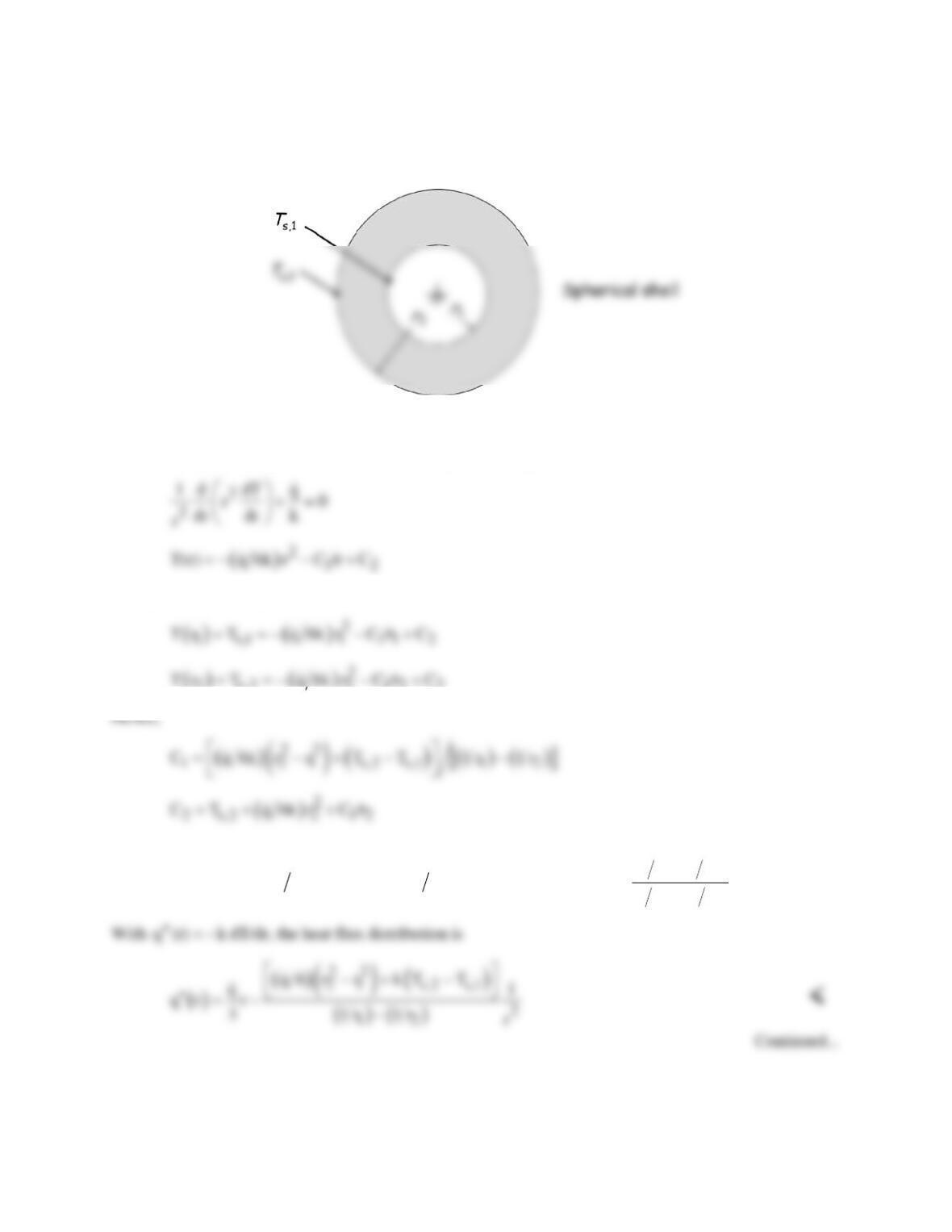
PROBLEM 3.72
KNOWN: Spherical shell with uniform heat generation and surface temperatures.
FIND: Radial distributions of temperature, heat flux and heat rate.
SCHEMATIC:
ASSUMPTIONS: (1) One-dimensional, steady-state conduction, (2) Uniform heat generation, (3)
Constant k.
ANALYSIS: For the spherical shell, the heat equation and general solution are
Applying the boundary conditions, it follows that
2 s,2 2 1 2 2
and
( ) ( )
()
( )
()
( )
( ) ( )
( ) ( )
22 22 2
s,2 2 2 1 s,2 s,1 12
1r 1r
T r T q 6k r r q 6k r r T T 1r 1r
−
= + −− −+ − −
<
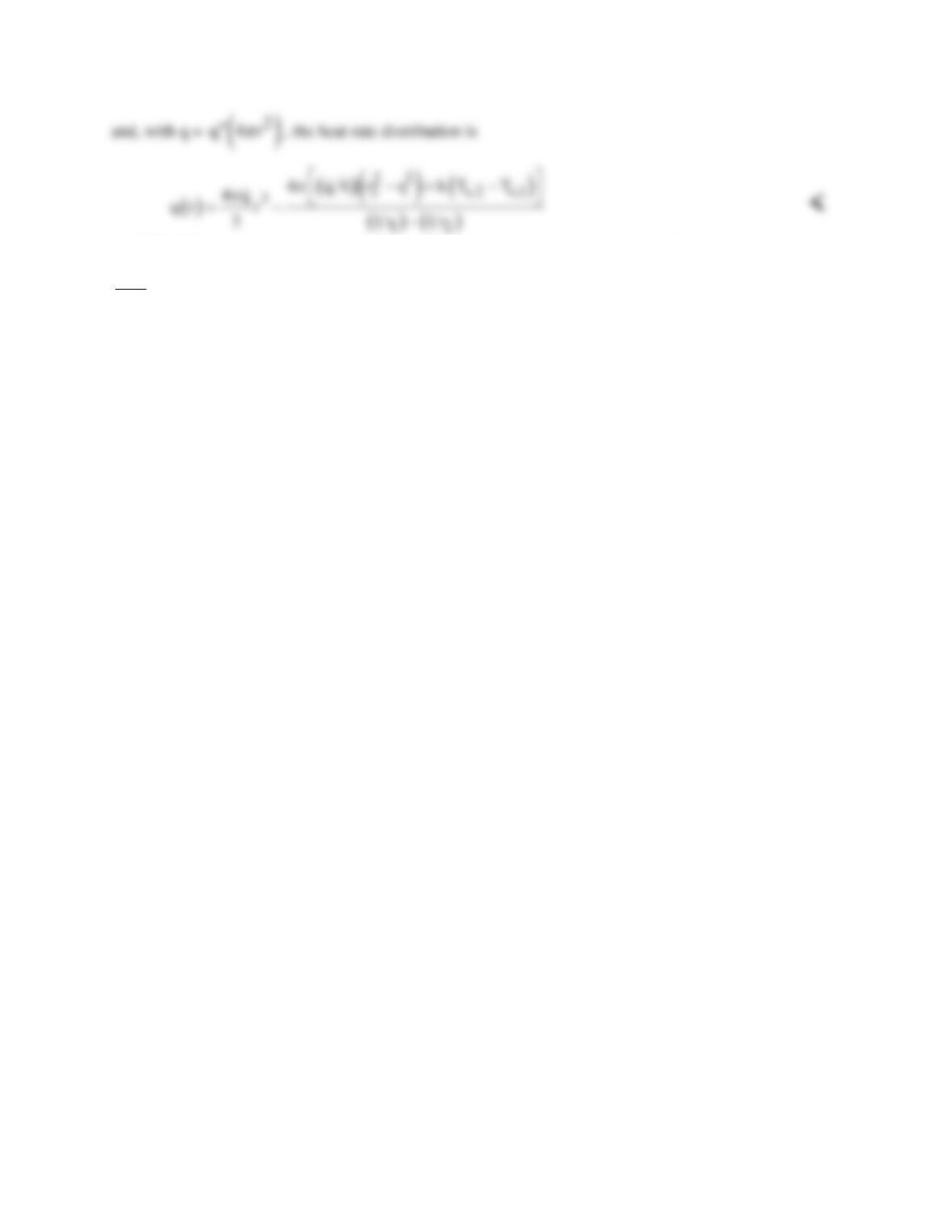
PROBLEM 3.72 (Cont.)
COMMENT: An overall energy balance on the sphere can be expressed as
( )
qr
21
q(r ) =−
()
4q 33
21
3r r qV
π
−=
where V is the volume of the spherical shell. Thus, the energy balance expresses
that the net rate at which energy leaves the shell is equal to the rate of energy generated within the shell.
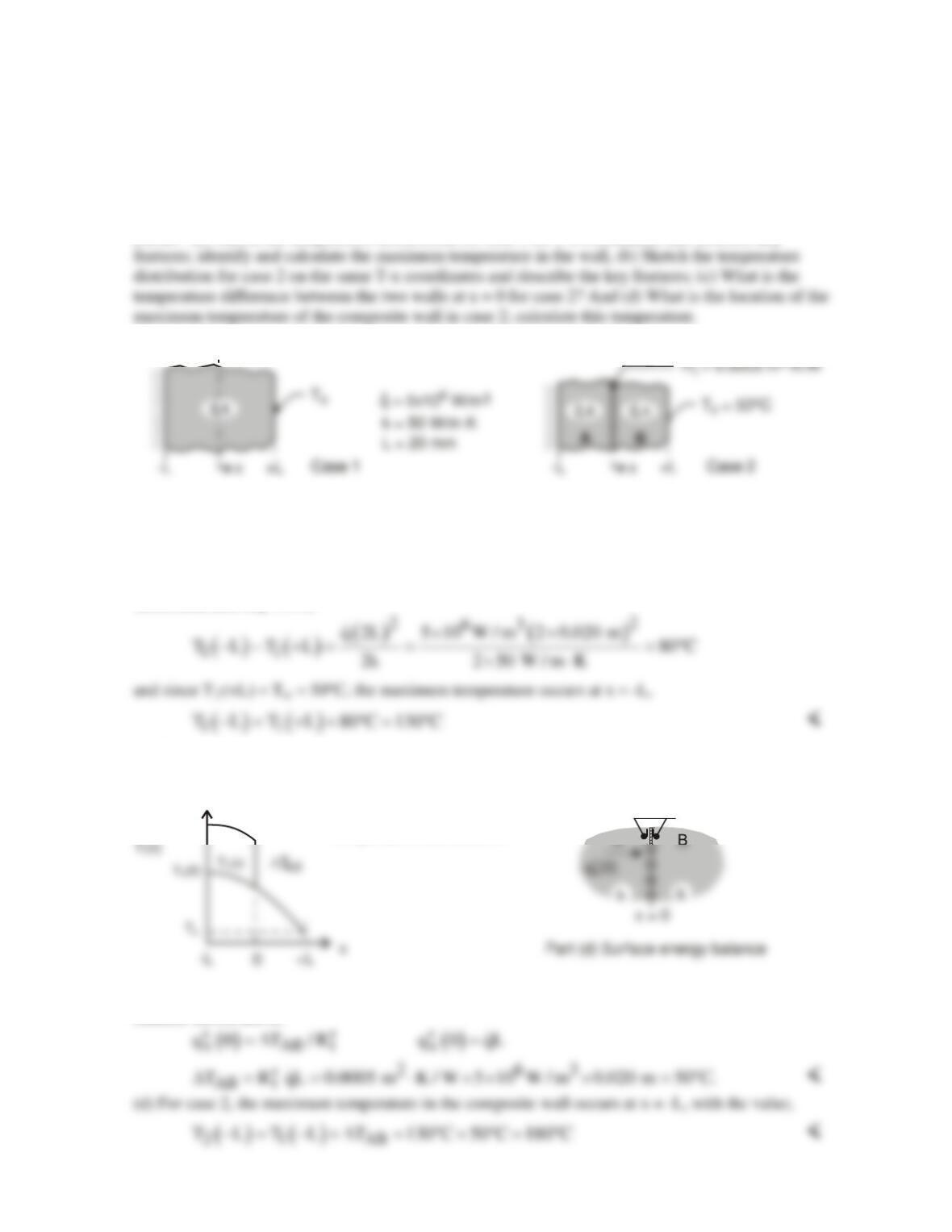
PROBLEM 3.73
KNOWN: Plane wall of thickness 2L, thermal conductivity k with uniform energy generation
q.
For case 1, boundary at x = -L is perfectly insulated, while boundary at x = +L is maintained at To =
50°C. For case 2, the boundary conditions are the same, but a thin dielectric strip with thermal
resistance
2
t
R 0.0005 m K / W
′′ = ⋅
is inserted at the mid–plane.
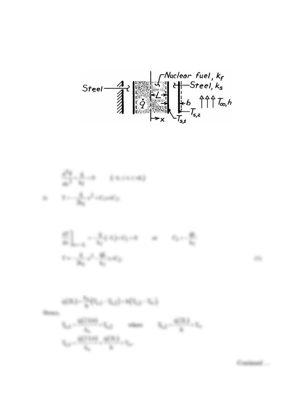
FIND: (a) Sketch the temperature distribution for case 1 on T-x coordinates and describe key
SCHEMATIC:
2
ASSUMPTIONS: (1) Steady-state conditions, (2) One-dimensional conduction in the plane and
composite walls, and (3) Constant properties.
ANALYSIS: (a) For case 1, the temperature distribution, T1(x) vs. x, is parabolic as shown in the
schematic below and the gradient is zero at the insulated boundary, x = –L. From Eq. 3.48 (see
discussion after Eq. 3.49),
(b) For case 2, the temperature distribution, T2(x) vs. x, is piece-wise parabolic, with zero gradient at
x = –L and a drop across the dielectric strip, ∆TAB. The temperature gradients at either side of the
dielectric strip are equal.
∆
T
AB
T (0)
2
T (x)
2
Parts (a,b)
Temperature distributions
(c) For case 2, the temperature drop across the thin dielectric strip follows from the surface energy
balance shown above.
PROBLEM 3.74
KNOWN: Geometry and boundary conditions of a nuclear fuel element.
FIND: (a) Expression for the temperature distribution in the fuel, (b) Form of temperature
distribution for the entire system.
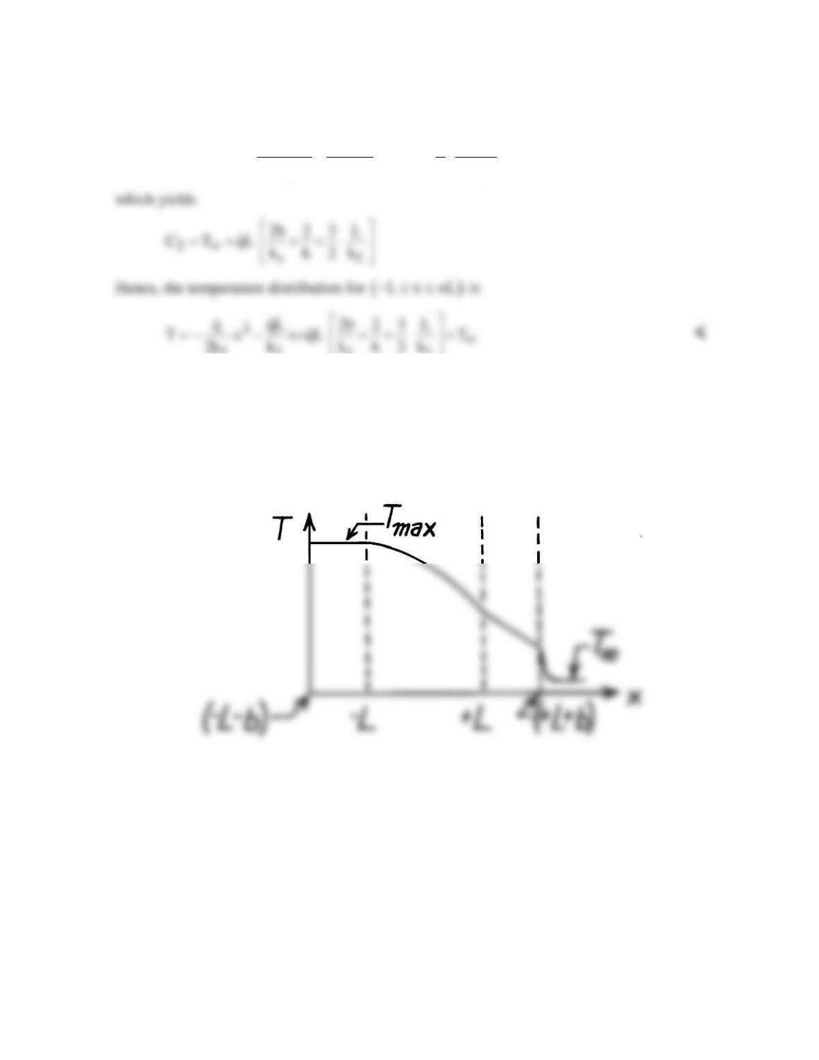
SCHEMATIC:
ASSUMPTIONS: (1) One-dimensional heat transfer, (2) Steady-state conditions, (3)
Uniform generation, (4) Constant properties, (5) Negligible contact resistance between fuel
and cladding.
ANALYSIS: (a) The general solution to the heat equation, Eq. 3.44,
The insulated wall at x = – (L+b) dictates that the heat flux at x = – L is zero (for an energy
balance applied to a control volume about the wall,
in out
E E 0).= =
Hence
The value of Ts,1 may be determined from the energy conservation requirement that
g cond conv
Eq q ,= =
or on a unit area basis.
PROBLEM 3.74 (Cont.)
Hence from Eq. (1),
( ) ( ) ( )
()
2
s,1 2
sf
qL
q 2 Lb q 2 L 3
TL T T C
k h 2k
∞
= = + +=− +
ff s f
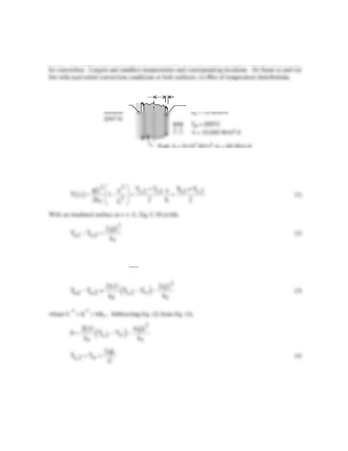
(b) For the temperature distribution shown below,
( )
( )
max
L b x L: dT/dx=0, T=T
L x +L: | dT/dx | with x
+L x L+b: dT/dx is const.
− − ≤ ≤−
−≤≤ ↑ ↑
≤≤
PROBLEM 3.75
KNOWN: Thermal conductivity, heat generation and thickness of fuel element. Thickness and
thermal conductivity of cladding. Surface convection conditions.
FIND: (a) Temperature distribution in fuel element with one surface insulated and the other cooled
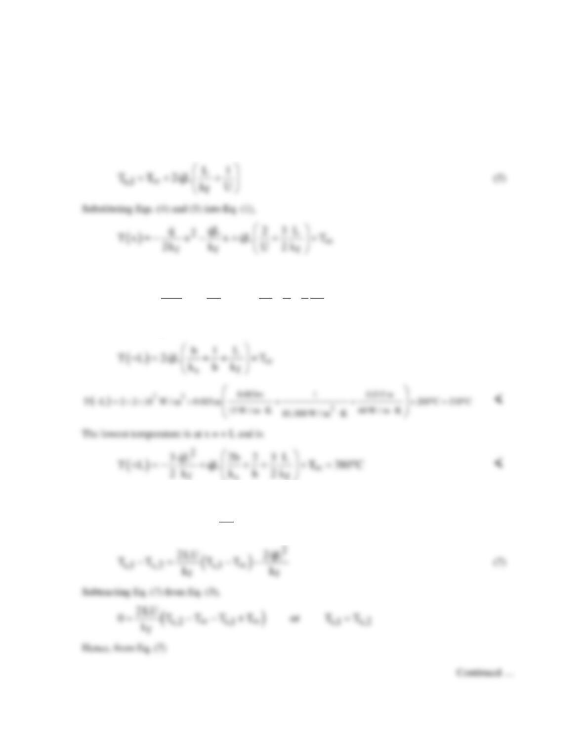
SCHEMATIC:
L = 0.15 m b = 0.003 m
Fuel, q = 2×10 W/m , k = 60 W/m-K
Cladding
Insulated
ASSUMPTIONS: (1) One-dimensional heat transfer, (2) Steady–state, (3) Uniform generation, (4)
Constant properties, (5) Negligible contact resistance.
ANALYSIS: (a) From Eq. C.1,
and with convection at x = L + b, Eq. C.13 yields
( ) ( )
f
s,2 s,2 s,1
k
UTTqL TT
2L
∞
−=− −
Continued …
15 mm
PROBLEM 3.75 (Cont.)
Alternatively, this result could have been found from an energy balance on the wall which equates the
generated heat to the heat leaving at L+b,
s,2
2qL U(T T )
∞
= −
Substituting Eq. (4) into Eq. (2)
Or,
( )
2
ff s f
q qL 2b 2 3 L
T x x x qL T
2k k k h 2 k ∞
=− − + ++ +
(6) <
The maximum temperature occurs at x = – L and is
(b) If a convection condition is maintained at x = – L, Eq. C.12 reduces to
( ) ( )
f
s,1 s,2 s,1
k
U T T qL T T
2L
∞− =−− −
PROBLEM 3.75 (Cont.)
s,1 s,2 s
qL 1 b
T T T qL T
U hk
∞∞
= =+= + +
(8)
Substituting into Eq. (1), the temperature distribution is
The minimum temperature at x = ± L is
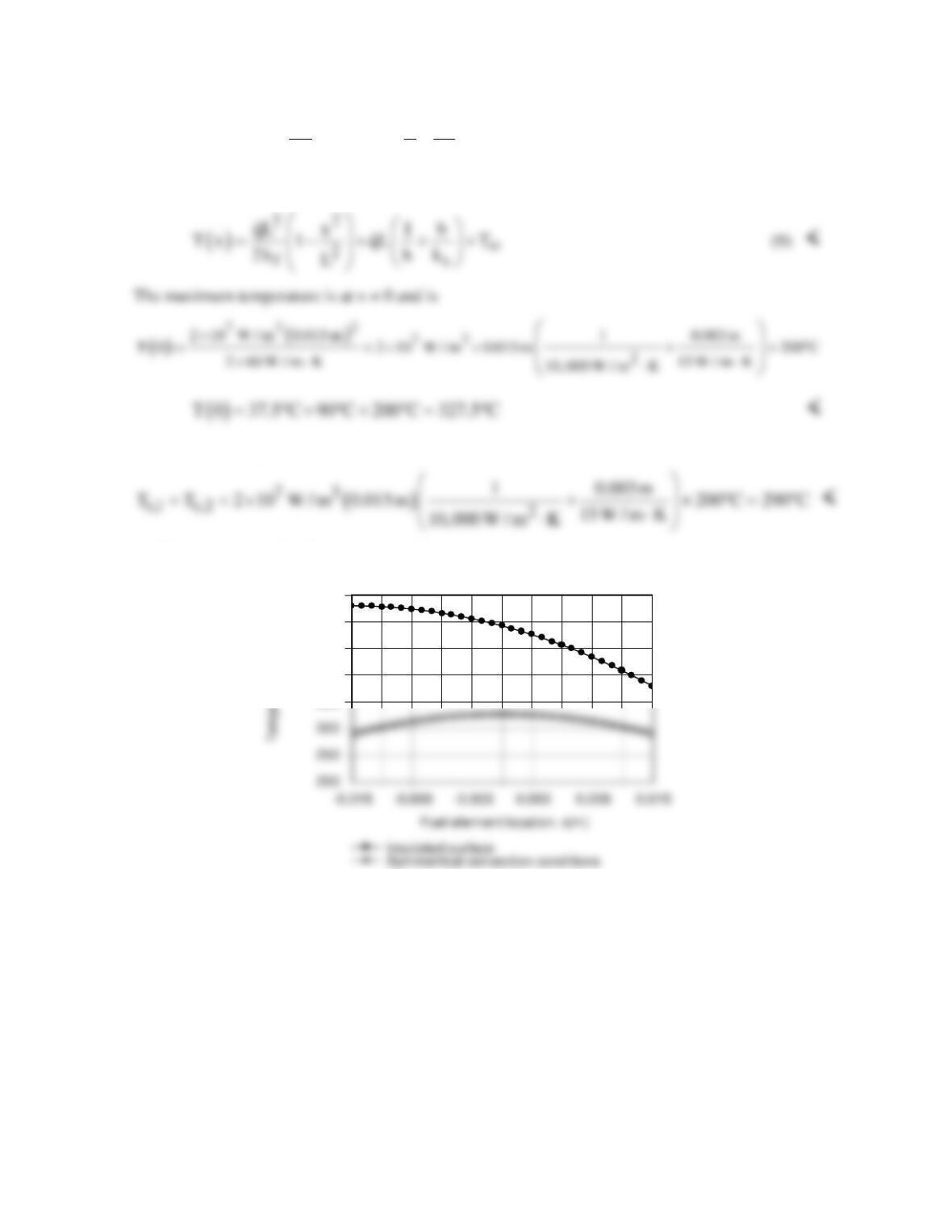
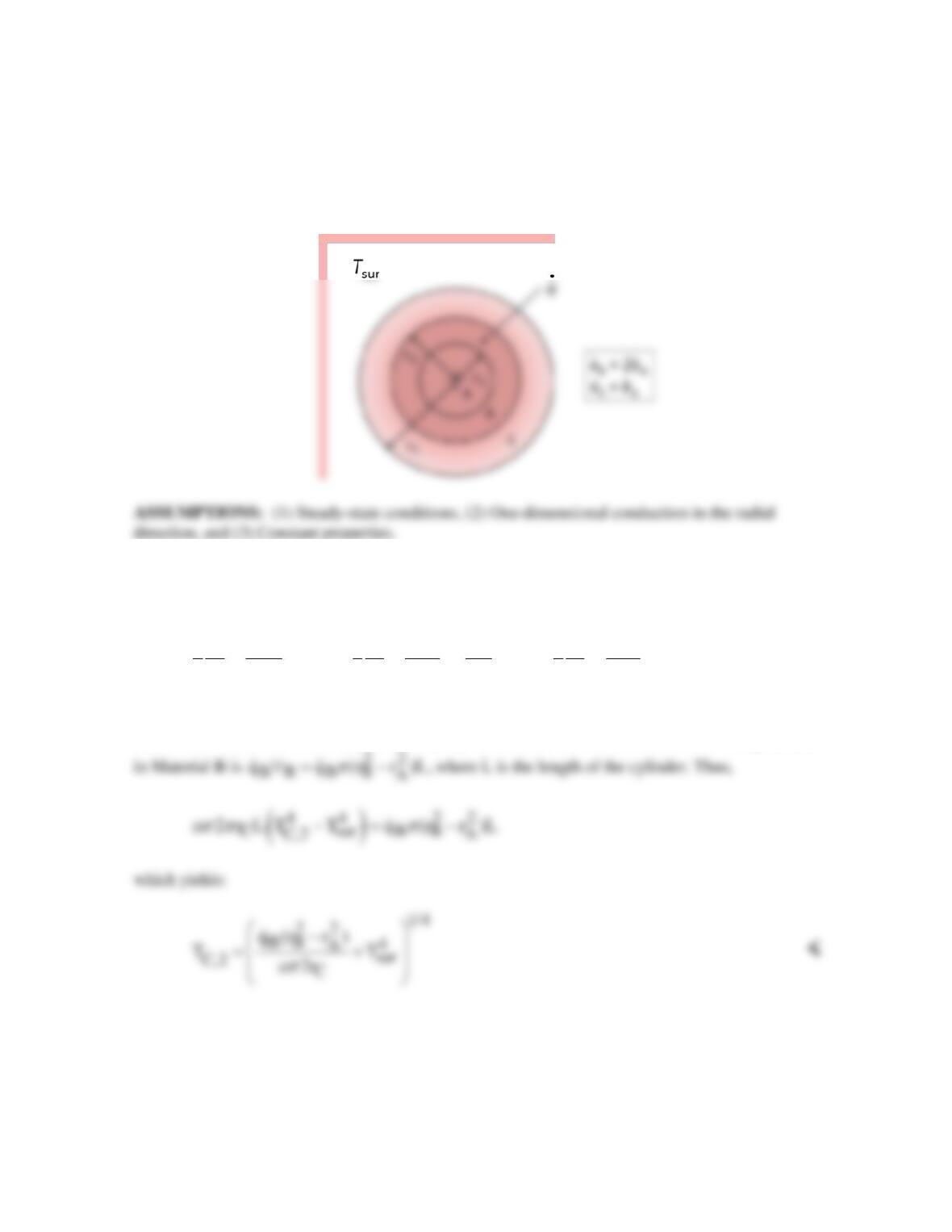
(c) The temperature distributions are as shown.
The amount of heat generation is the same for both cases, but the ability to transfer heat from both
surfaces for case (b) results in lower temperatures throughout the fuel element.
COMMENTS: Note that for case (a), the temperature in the insulated cladding is constant and
equivalent to Ts,1 = 530°C.
350
400
450
500
550
PROBLEM 3.76
KNOWN: Three-layer composite cylinder with specified dimensions, thermal conductivities, and
contact resistances, with uniform energy generation
q
in one layer. Radiation loss at the surface.
FIND: (a) Heat equation in each material, (b) Temperature at surface of Material C; (c) Sketch of
temperature distribution, and (d) Sketch of heat flux distribution.
SCHEMATIC:
ANALYSIS: (a) The heat equation in cylindrical radial coordinates with heat generation and
constant thermal conductivity is given in Equation 3.54. There is heat generation in Material B, but
not in Materials A and C. Therefore the heat equations can be written:
C
A BB
B
dT
dT dT q
1d 1d 1d
r 0, r 0, r 0
r dr dr r dr dr k r dr dr
= += =
<
(b) The temperature at the surface, T(rC), can be found by recognizing that the heat generated in
Material B must leave the composite cylinder by radiation at the surface. The rate of heat generation
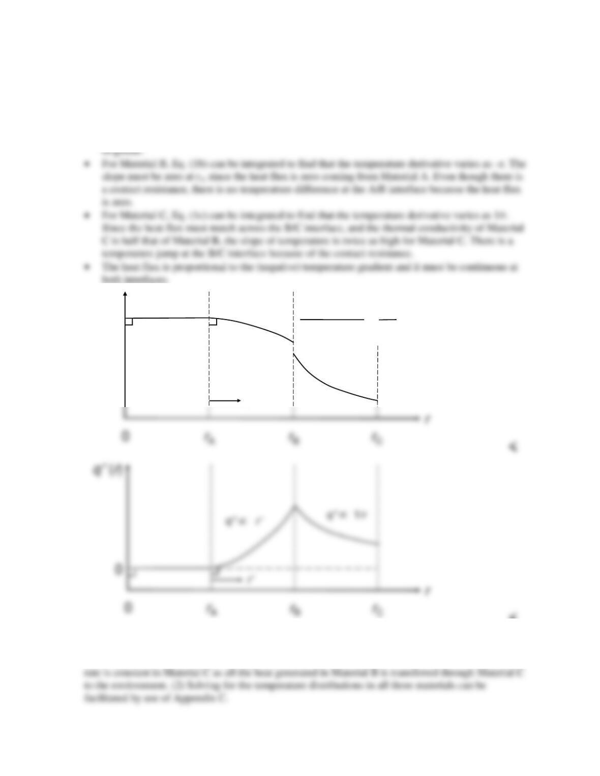
(c,d) The sketches are shown below. These sketches can be developed through the following
considerations:
Continued …
PROBLEM 3.76 (Cont.)
• For Material A, the differential equation, Eq. (1a), can be multiplied by r and integrated once to
give
A1
dT / dr C .=
Recognizing that the point r = 0 is a symmetry point, the temperature
gradient at r = 0 must be zero, therefore C1 = 0. Thus TA is a constant. From a more physical
perspective, there can be no heat transfer within Material A because it only has one surface; if
heat enters at that surface, it has nowhere to go. If heat leaves at that surface, it has nowhere to
T(r)
dT/dr –r’
dT/dr 1/r
∝
∝
r’
dTC/dr |r= rB
dTB/dr |r= rB
kB
kC
== 2
<
COMMENTS: (1) The heat transfer rate is zero in Material A. The heat transfer rate increases as
radius squared in Material B as more generated heat must exit toward Material C. The heat transfer
PROBLEM 3.77
KNOWN: Plane wall with prescribed nonuniform volumetric generation having one
boundary insulated and the other isothermal.
FIND: Temperature distribution, T(x), in terms of x, L, k,
oo
q and T .
SCHEMATIC:
ASSUMPTIONS: (1) Steady-state conditions, (2) One-dimensional conduction in x-
direction, (3) Constant properties.
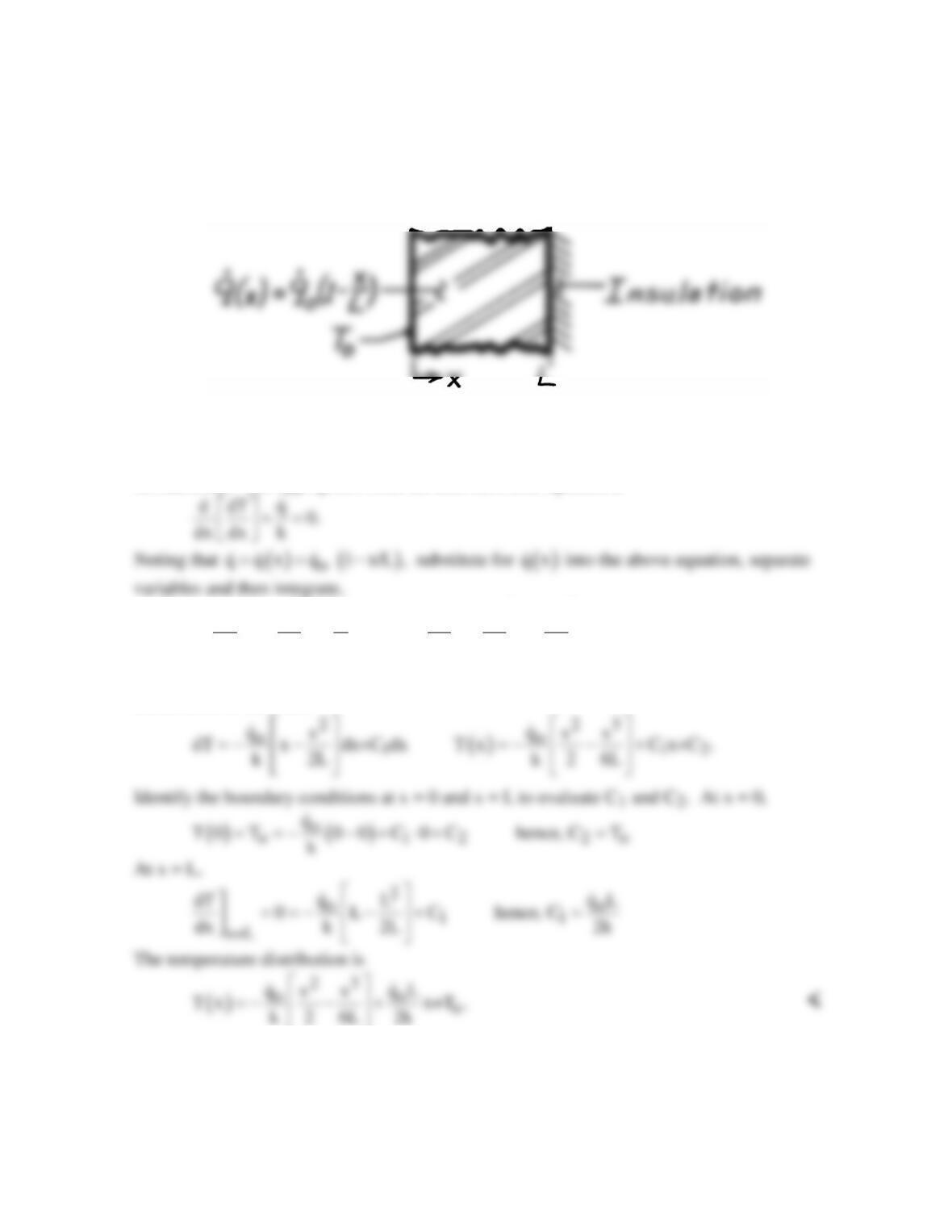
ANALYSIS: The appropriate form the heat diffusion equation is
2
oo
1
qq
dT x dT x
d 1 dx x C .
dx k L dx k 2L
=− − =− −+
Separate variables and integrate again to obtain the general form of the temperature
distribution in the wall,
COMMENTS: It is good practice to test the final result for satisfying BCs. The heat flux at
x = 0 can be found using Fourier’s law or from an overall energy balance
L
out g out o
0
E E qdV to obtain q q L/2.
′′
= = =
∫
PROBLEM 3.78
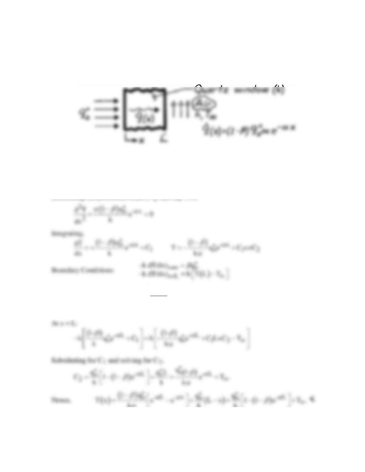
KNOWN: Distribution of volumetric heating and surface conditions associated with a quartz
window.
FIND: Temperature distribution in the quartz.
SCHEMATIC:
ASSUMPTIONS: (1) Steady-state conditions, (2) One-dimensional conduction, (3)
Negligible radiation emission and convection at inner surface (x = 0) and negligible emission
from outer surface, (4) Constant properties.
ANALYSIS: The appropriate form of the heat equation for the quartz is obtained by
substituting the prescribed form of
q
into Eq. 3.44.
Hence, at x = 0:
( )
o1 o
1o
1-
k qC q
k
C q /k
ββ
′′ ′′
− +=
′′
= −
k kh
α
COMMENTS: The temperature distribution depends strongly on the radiative coefficients, α
and β. For α → ∞ or β = 1, the heating occurs entirely at x = 0 (no volumetric heating).
PROBLEM 3.79
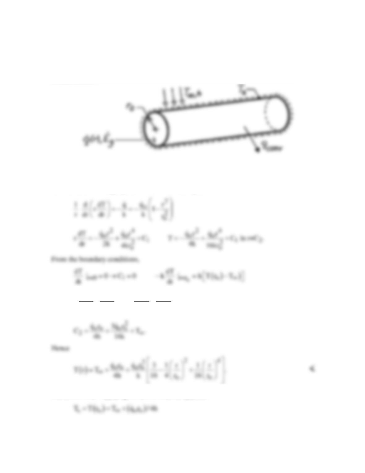
KNOWN: Radial distribution of heat dissipation in a cylindrical container of radioactive
wastes. Surface convection conditions.
FIND: Radial temperature distribution.
SCHEMATIC:
ASSUMPTIONS: (1) Steady-state conditions, (2) One-dimensional conduction, (3) Constant
properties, (4) Negligible temperature drop across container wall.
ANALYSIS: The appropriate form of the heat equation is
22
oo oo oo oo 2
qr qr qr qr
h CT
2 4 4k 16k
∞
+ − =− + +−
COMMENTS: Applying the above result at ro yields
The same result may be obtained by applying an energy balance to a control surface about the
container, where
g conv
Eq .=
The maximum temperature exists at r = 0.
PROBLEM 3.80
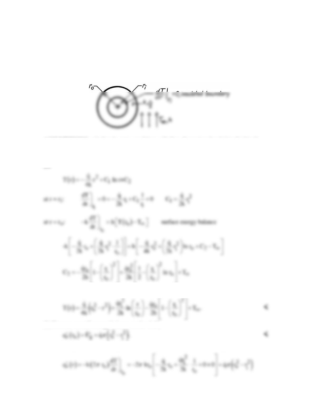
KNOWN: Cylindrical shell with uniform volumetric generation is insulated at inner surface
and exposed to convection on the outer surface.
FIND: (a) Temperature distribution in the shell in terms of
io
r , r , q, h, T and k,
∞
(b)
Expression for the heat rate per unit length at the outer radius,
( )
o
qr .
′
SCHEMATIC:
ASSUMPTIONS: (1) Steady-state conditions, (2) One-dimensional radial (cylindrical)
conduction in shell, (3) Uniform generation, (4) Constant properties.
ANALYSIS: (a) The general form of the temperature distribution and boundary conditions
are
Hence,
(b) From an overall energy balance on the shell,
Alternatively, the heat rate may be found using Fourier’s law and the temperature distribution,
PROBLEM 3.81
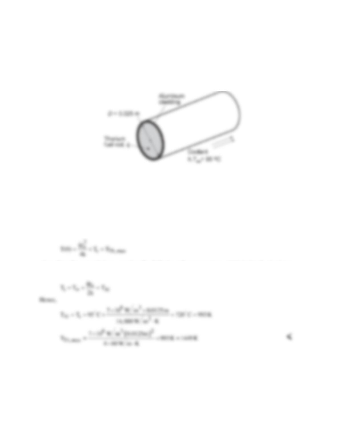
KNOWN: Energy generation in an aluminum-clad, thorium fuel rod under specified operating
conditions.
FIND: (a) Whether prescribed operating conditions are acceptable, (b) Effect of
q
and h on acceptable
operating conditions.
SCHEMATIC:
ASSUMPTIONS: (1) One-dimensional conduction in r-direction, (2) Steady-state conditions, (3)
Constant properties, (4) Negligible temperature gradients in aluminum and contact resistance between
aluminum and thorium.
PROPERTIES: Table A-1, Aluminum, pure: M.P. = 933 K; Table A-1, Thorium: M.P. = 2023 K, k ≈
60 W/m⋅K.
ANALYSIS: (a) System failure would occur if the melting point of either the thorium or the aluminum
were exceeded. From Eq. 3.58, the maximum thorium temperature, which exists at r = 0, is
where, from the energy balance equation, Eq. 3.60, the surface temperature, which is also the aluminum
temperature, is
Although TTh,max < M.P.Th and the thorium would not melt, Tal > M.P.Al and the cladding would melt
under the proposed operating conditions. The problem could be eliminated by decreasing
q
or ro,
increasing h or using a cladding material with a higher melting point.
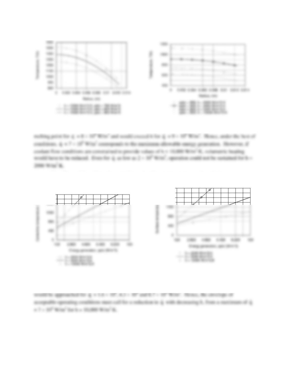
(b) Using the one-dimensional, steady-state conduction model (solid cylinder) of the IHT software, the
following radial temperature distributions were obtained for parametric variations in
q
and h.
Continued…
PROBLEM 3.81 (Cont.)
For h = 10,000 W/m2⋅K, which represents a reasonable upper limit with water cooling, the temperature of
the aluminum would be well below its melting point for
q
= 7 × 10⁸ W/m3, but would be close to the
q
q
The effects of
q
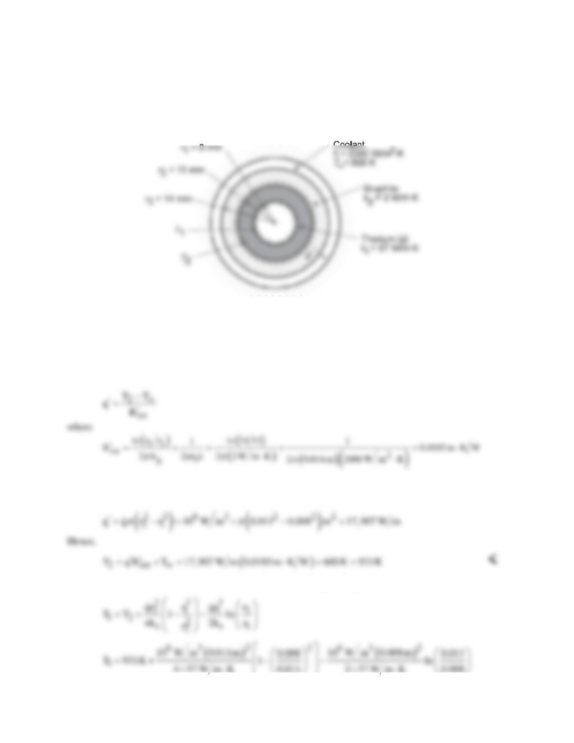
and h on the centerline and surface temperatures are shown below.
2000
1600
2000
For h = 2000 and 5000 W/m2⋅K, the melting point of thorium would be approached for
q
≈ 4.4 × 10⁸ and
8.5 × 10⁸ W/m3, respectively. For h = 2000, 5000 and 10,000 W/m2⋅K, the melting point of aluminum
q
q
COMMENTS: Note the problem which would arise in the event of a loss of coolant, for which case h
would decrease drastically.
PROBLEM 3.82
KNOWN: Materials, dimensions, properties and operating conditions of a gas-cooled nuclear reactor.
FIND: (a) Inner and outer surface temperatures of fuel element, (b) Temperature distributions for
different heat generation rates and maximum allowable generation rate.
SCHEMATIC:
ASSUMPTIONS: (1) Steady-state conditions, (2) One-dimensional conduction, (3) Constant properties,
(4) Negligible contact resistance, (5) Negligible radiation.
PROPERTIES: Table A.1, Thorium: Tmp ≈ 2000 K; Table A.2, Graphite: Tmp ≈ 2300 K.
ANALYSIS: (a) The outer surface temperature of the fuel, T2, may be determined from the rate
equation
and the heat rate per unit length may be determined by applying an energy balance to a control surface
about the fuel element. Since the interior surface of the element is essentially adiabatic, it follows that
With zero heat flux at the inner surface of the fuel element, Eq. C.14 yields
4 57 W m K 0.011 2 57 W m K 0.008
×⋅ ×⋅
Continued…
PROBLEM 3.82 (Cont.)
1
T 931K 25 K 18 K 938 K= +−=
<
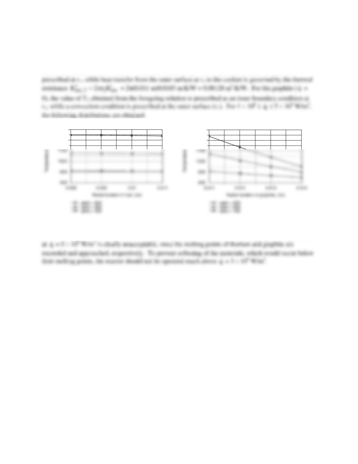
(b) The temperature distributions may be obtained by using the IHT model for one-dimensional, steady-
state conduction in a hollow tube. For the fuel element (
q
> 0), an adiabatic surface condition is
2100
2500
2100
2500
The comparatively large value of kt yields small temperature variations across the fuel element,
while the small value of kg results in large temperature variations across the graphite. Operation
q
q
COMMENTS: A contact resistance at the thorium/graphite interface would increase temperatures in the
fuel element, thereby reducing the maximum allowable value of
q
.
q
PROBLEM 3.83
KNOWN: Long rod experiencing uniform volumetric generation encapsulated by a circular
sleeve exposed to convection.
FIND: (a) Temperature at the interface between rod and sleeve and on the outer surface, (b)
Temperature at center of rod.
ASSUMPTIONS: (1) One-dimensional radial conduction in rod and sleeve, (2) Steady–state
conditions, (3) Uniform volumetric generation in rod, (4) Negligible contact resistance
between rod and sleeve.
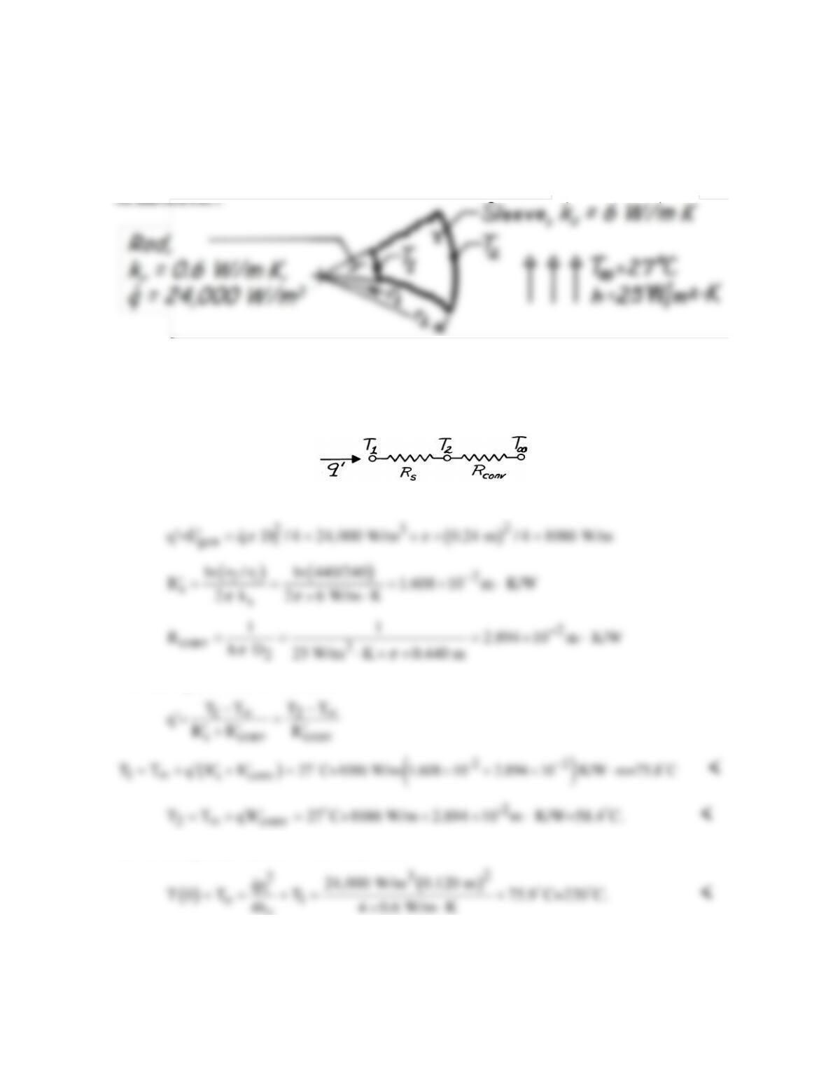
ANALYSIS: (a) Construct a thermal circuit for the sleeve,
where
The rate equation can be written as
(b) The temperature at the center of the rod is
r
COMMENTS: The thermal resistances due to conduction in the sleeve and convection are
comparable. Will increasing the sleeve outer diameter cause the surface temperature T2 to
increase or decrease?