24.48fth=
or
Problem 3.124
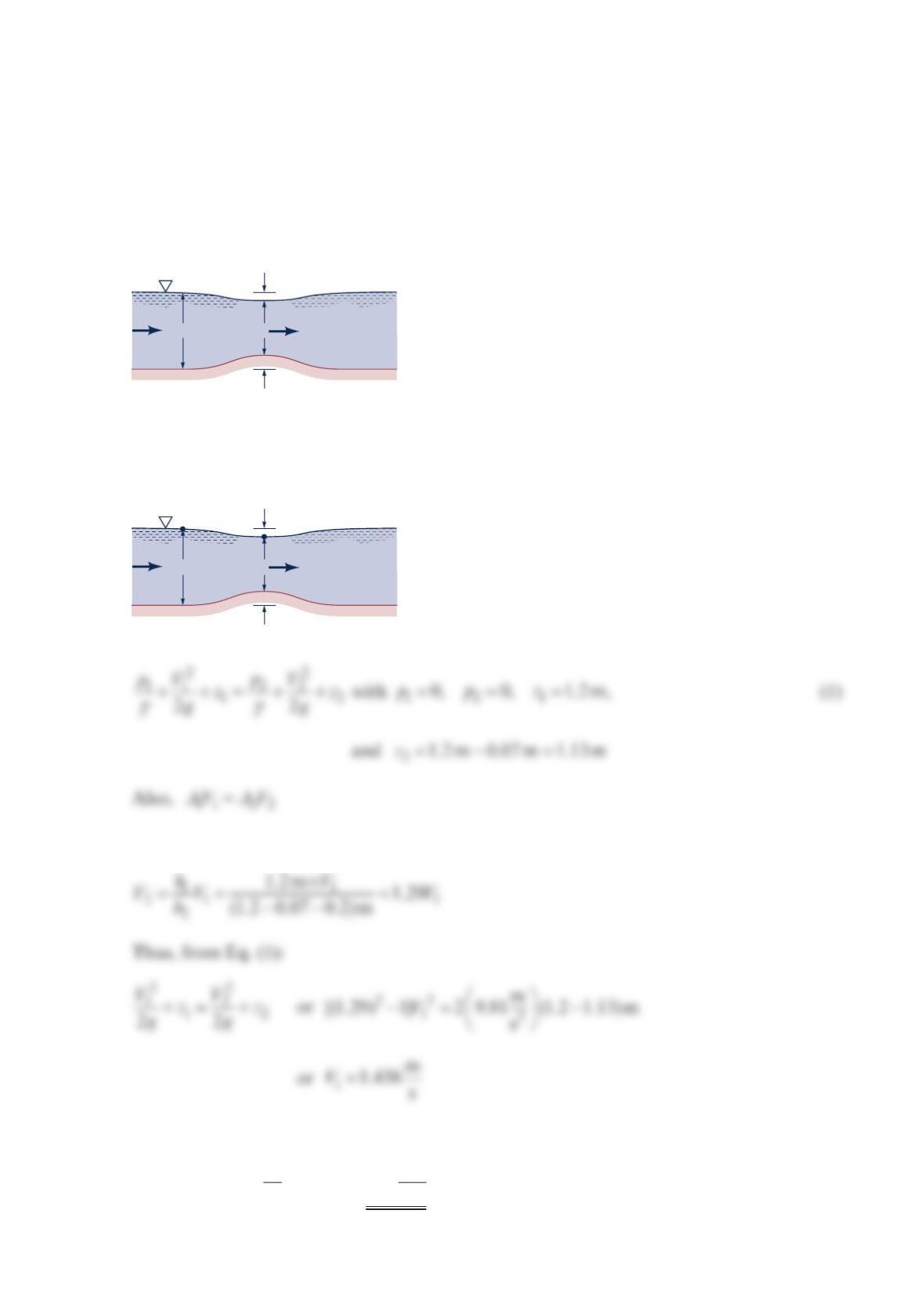
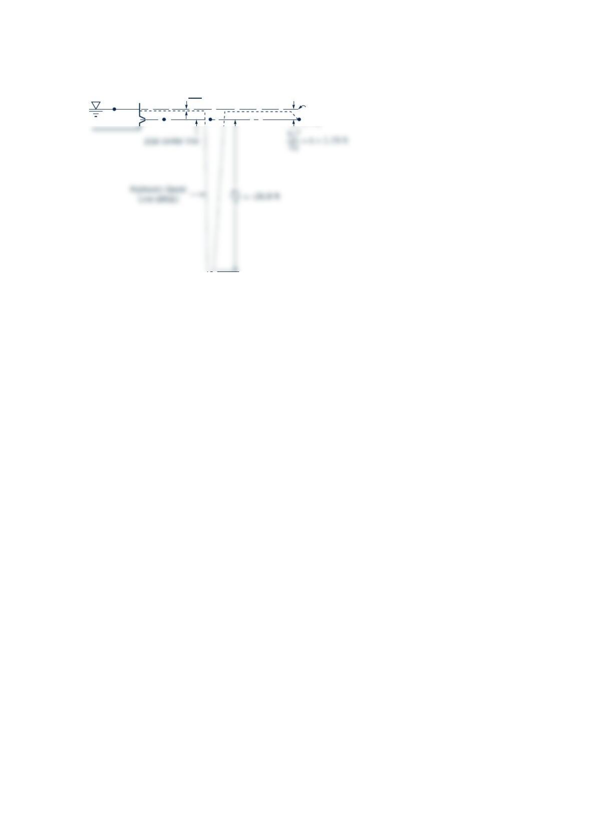
Water flows in a rectangular channel that is 2.0 m wide as shown in the figure below. The
upstream depth is 70 mm . The water surface rises 40 mm as it passes over a portion where
the channel bottom rises10 mm . If viscous effects are negligible, what is the flowrate?
Solution 3.124
Also,
11 2 2
AV A V=
or
Q
10 mm
100 mm
70 mm
100 mm
70 mm
(1)
(2)
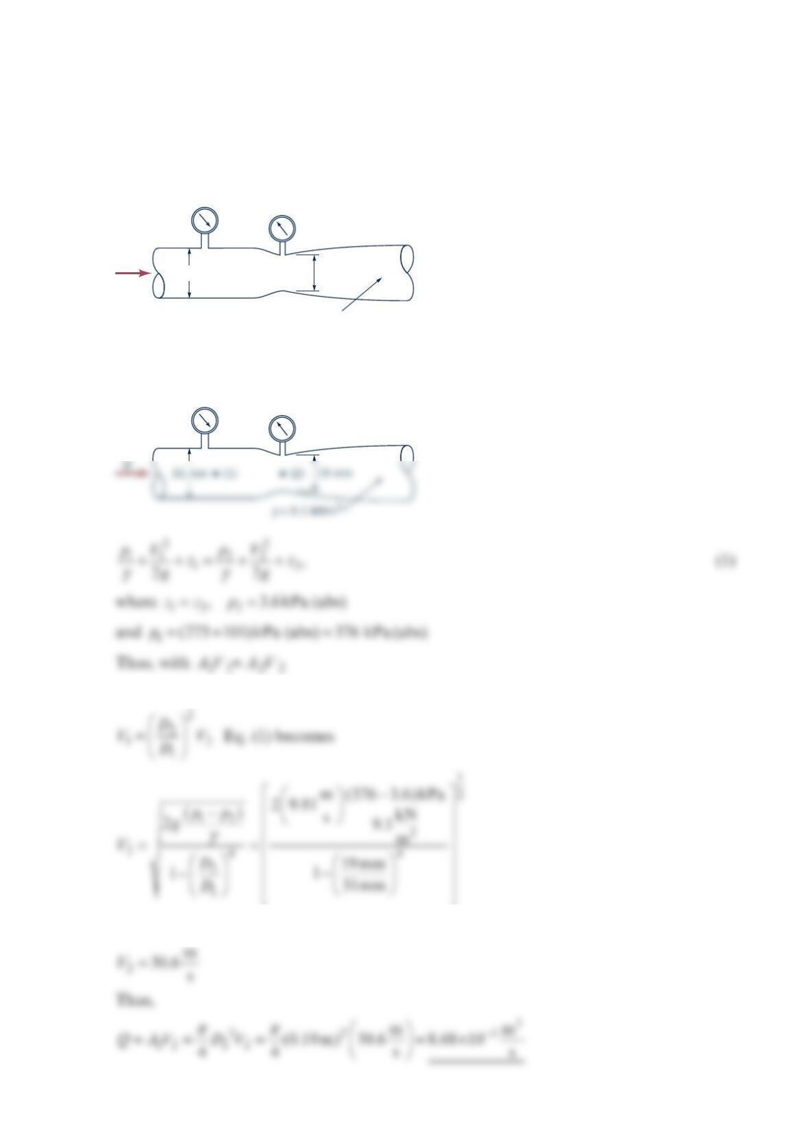
Problem 3.126
A Venturi meter with a minimum diameter of 3in. is to be used to measure the flowrate of
water through a 4-in.-diameter pipe. Determine the pressure difference indicated by the
pressure gage attached to the flowmeter if the flowrate is
3
ft
0.5 s and viscous effects are
negligible.
Solution 3.126
Thus, since
2
22
11
,
AD
AD
=
V1V2
Problem 3.127
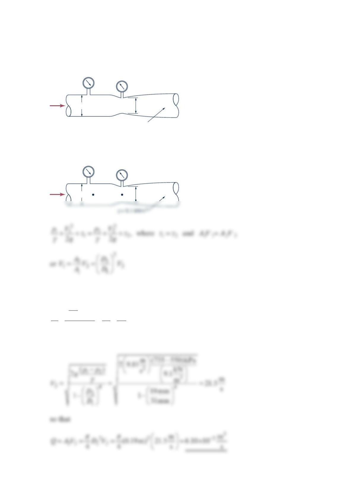
Determine the flowrate through the Venturi meter shown in the figure below if ideal condi-
tions exist.
Solution 3.127
Thus,
4
2
222
1
122
22
DV
D
p
pV
gg
γγ
+=+
or
p
1 = 735 kPa
p
2 = 550 kPa
Q
19 mm
31 mm
γ
= 9.1 kN/m3
p
1 = 735 kPa
p
2 = 550 kPa
Q
19 mm
31 mm
(1) (2)
Problem 3.128
For what flowrate through the Venturi meter shown in the figure below will cavitation
begin if 1275kPap= gage, atmospheric pressure is 101kPa (abs), and the vapor pressure is
3.6 kPa (abs) if ideal conditions exist?
Solution 3.128
or
or
Q
19 mm
31 mm
γ
= 9.1 kN/m
3
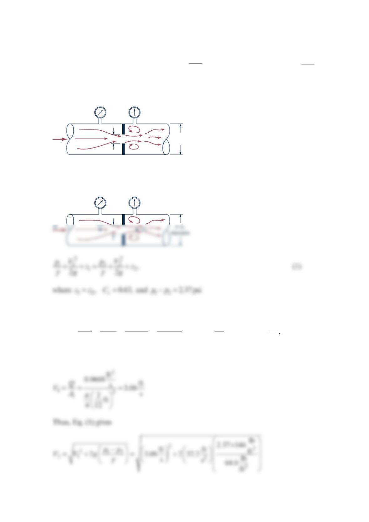
Problem 3.129
What diameter orifice hole, d, is needed if under ideal conditions the flowrate through the
orifice meter of the figure below is to be gal
3
0min of seawater with 12 2
lb
2.37 in.
p
p−= ? The
contraction coefficient is assumed to be 0.63 .
Solution 3.129
With
33 3
3
gal 1min 231in. 1ft ft
30 0.0668
min 60s 1gal s
1728in
Q
==
and 3
lb
64.0 ft
γ
=
it follows that
p
1
p
2
2-in.
diameter
d
Q
p
1
p
2
d
or
2
ft
18.8 s
V
=
Thus, since
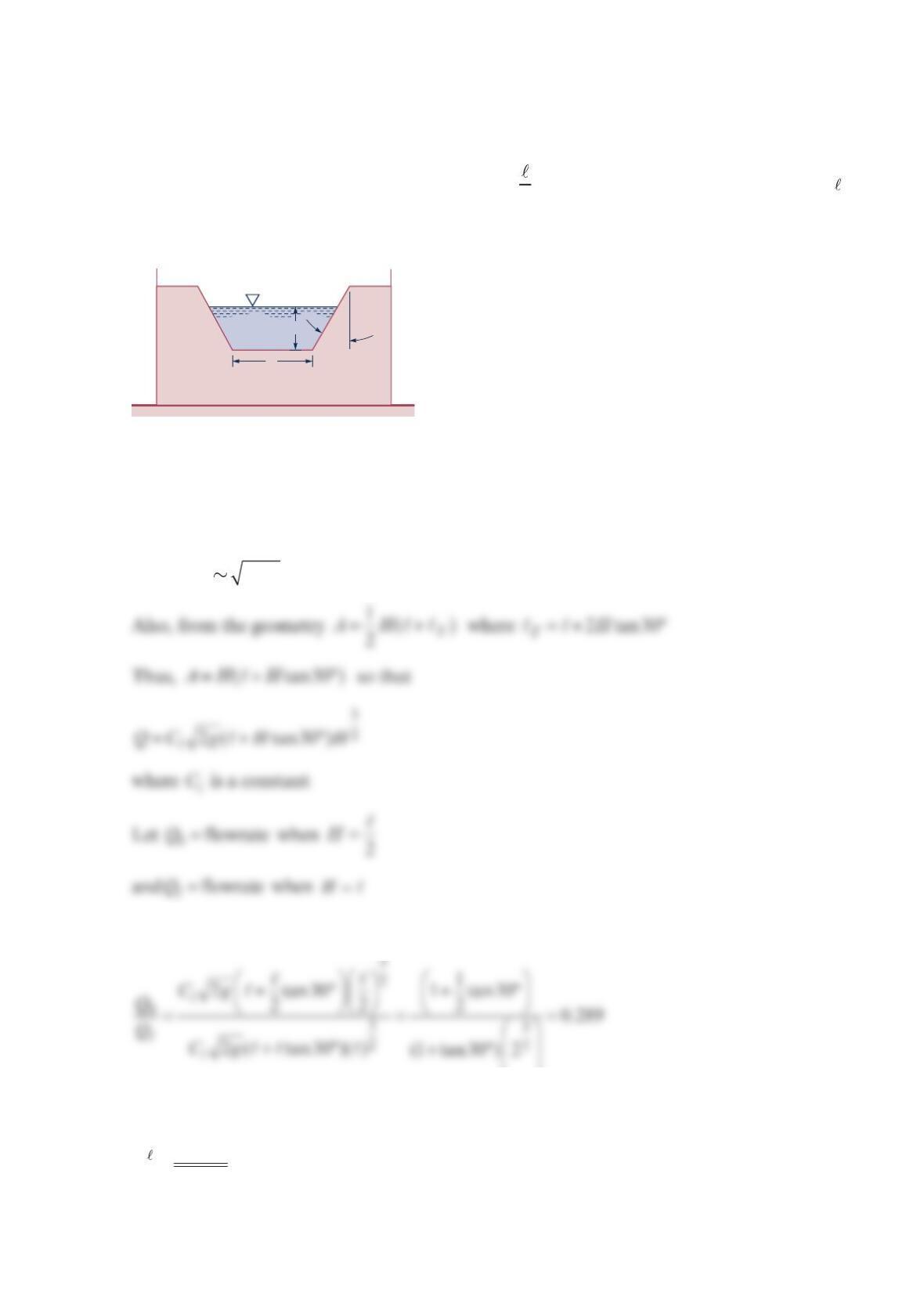
Problem 3.130
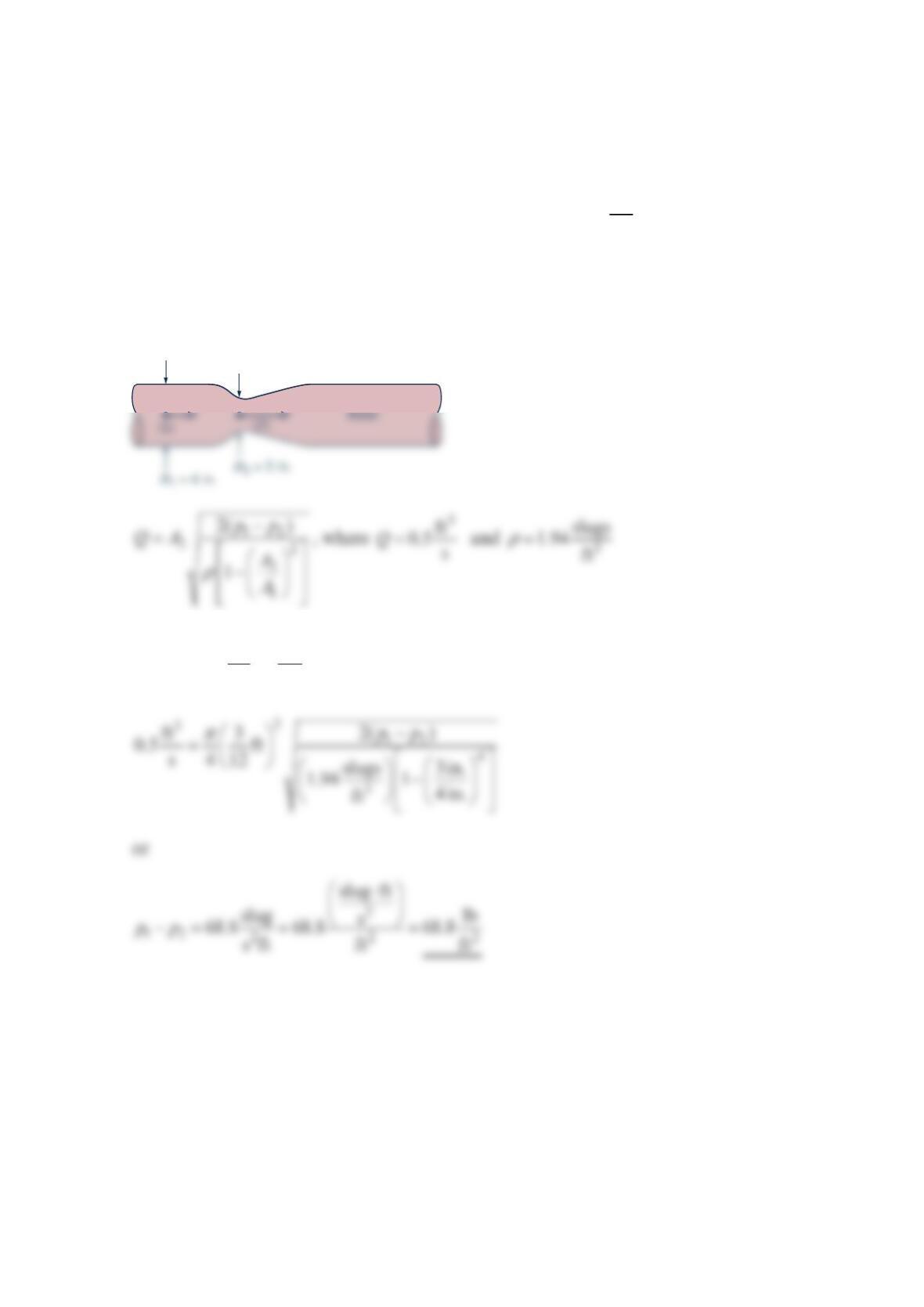
A weir of trapezoidal cross section is used to measure the flowrate in a channel as shown in
the figure below. If the flowrate is 0
Qwhen 2
H=, what flowrate is expected when H=?
Solution 3.130
QAV= where it is expected that V is a function of the head, H.
That is, 2VgH
Thus,
or
0
3.46QQ=
H
30°
ℓ
Problem 3.131
The flowrate in a water channel is sometimes determined by use of a device called a Venturi
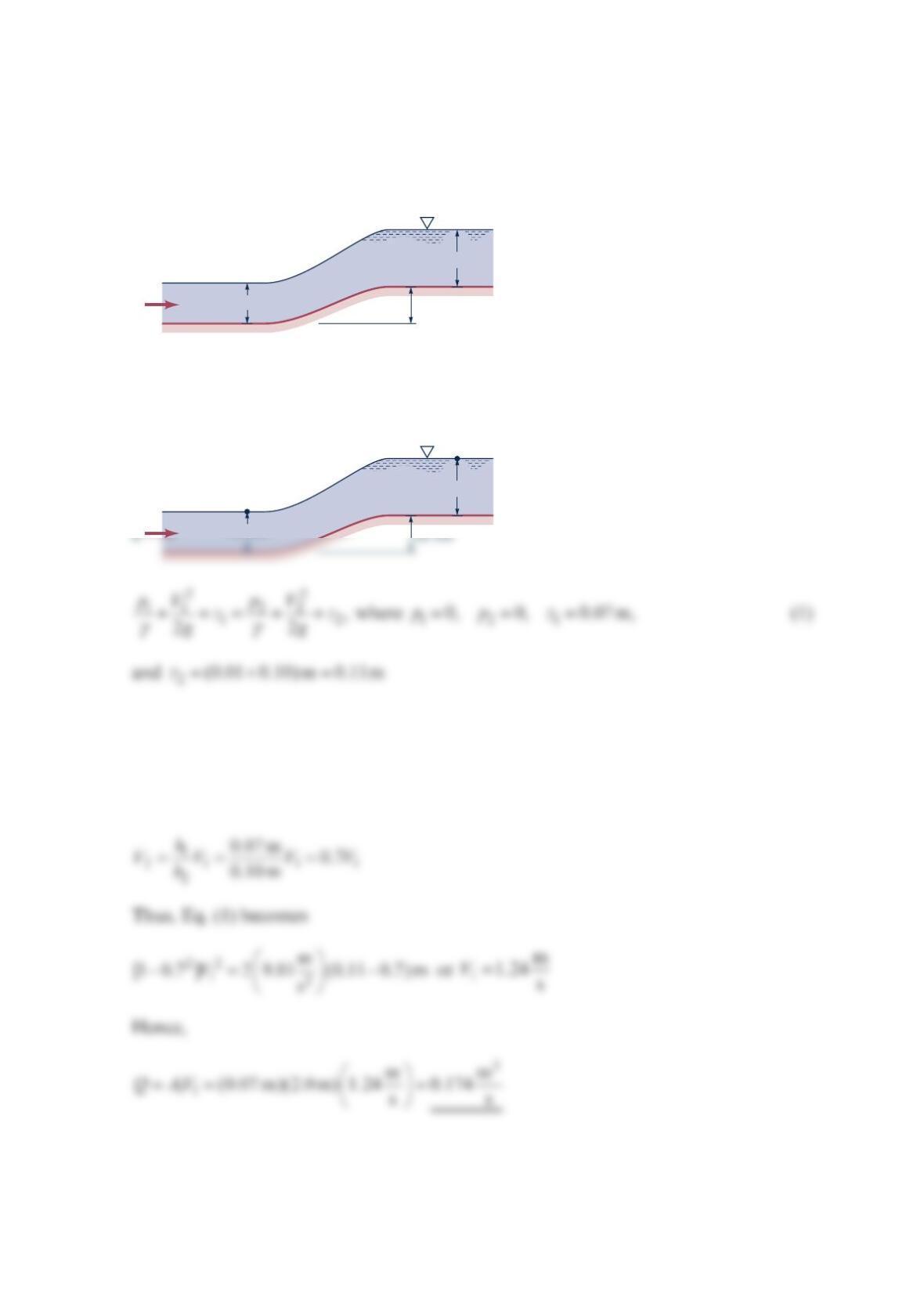
flume. As shown in the figure below, this device consists simply of a bump on the bottom of
the channel. If the water surface dips a distance of 0.07 m for the conditions shown, what
is the flowrate per width of the channel? Assume the velocity is uniform and viscous effects
are negligible.
Solution 3.131
or
Hence,
2
11
mm
1.438 (1.2 m) 1.73
ss
ghV
== =
0.07 m
0.2 m
1.2 m
V
2
V
1
0.07 m
0.2 m
1.2 m
V
2
V
1
(1) (2)
Problem 3.132
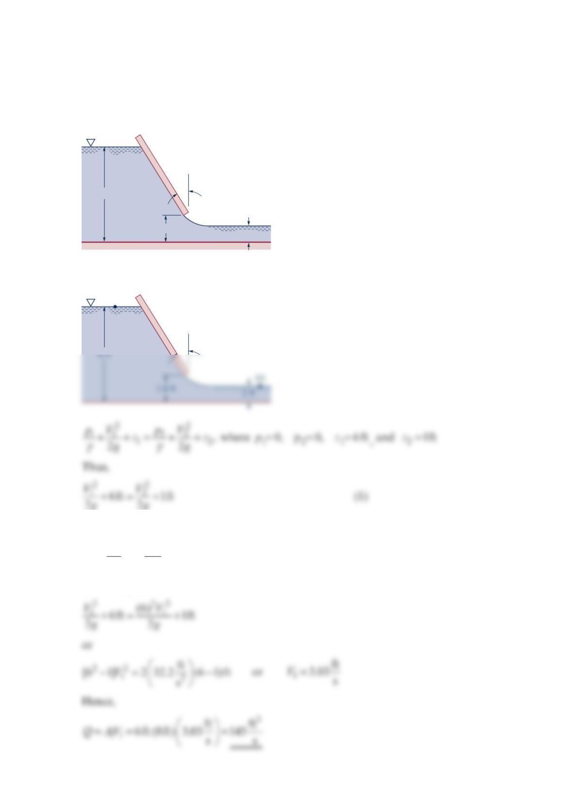
Water flows under the inclined sluice gate shown in the figure below. Determine the
flowrate if the gate is 8ft wide.
Solution 3.132
But 11 2 2
,AV A V= or
1
21 11
2
6ft 6
1ft
A
VVVV
A
== =
Hence, Eq. (1) becomes
6 ft
1.6 ft 1 ft
30°
30°
(1)
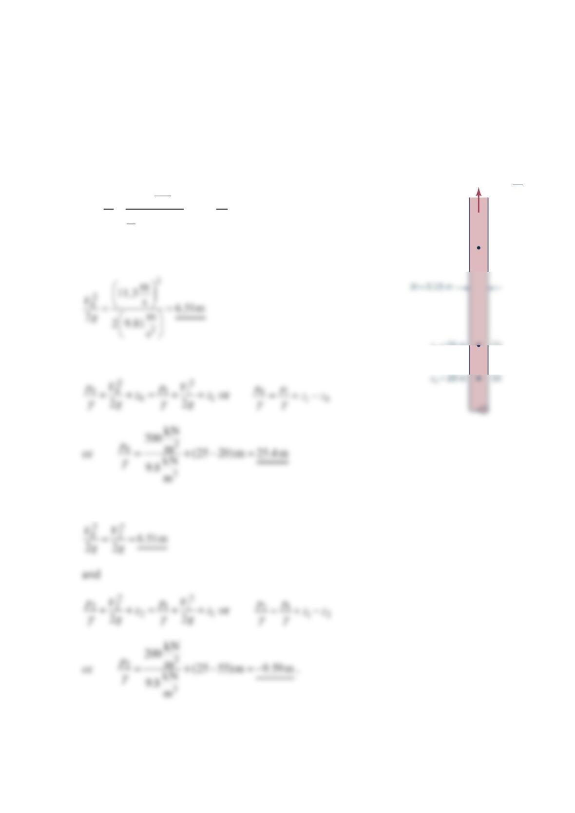
Problem 3.133
Water flows in a vertical pipe of 0.15 m diameter at a rate of 3
0.2 m / s and a pressure of
200 kPa at an elevation of 25 m . Determine the velocity head and pressure head at
elevations of 20 and 55 m .
Solution 3.133
3
02
2
m
0.2 m
s11.3 s
(0.15m)
4
Q
VVV
A
π
== = = =
At point (0):
and
Similarly, at point (2):
(2)
(1)
z2
= 55 m
z1
= 25 m
p1
= 200 kPa
Q
= 0.2 s
m
3
Problem 3.134
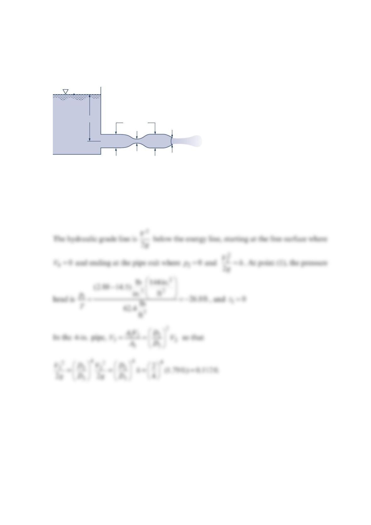
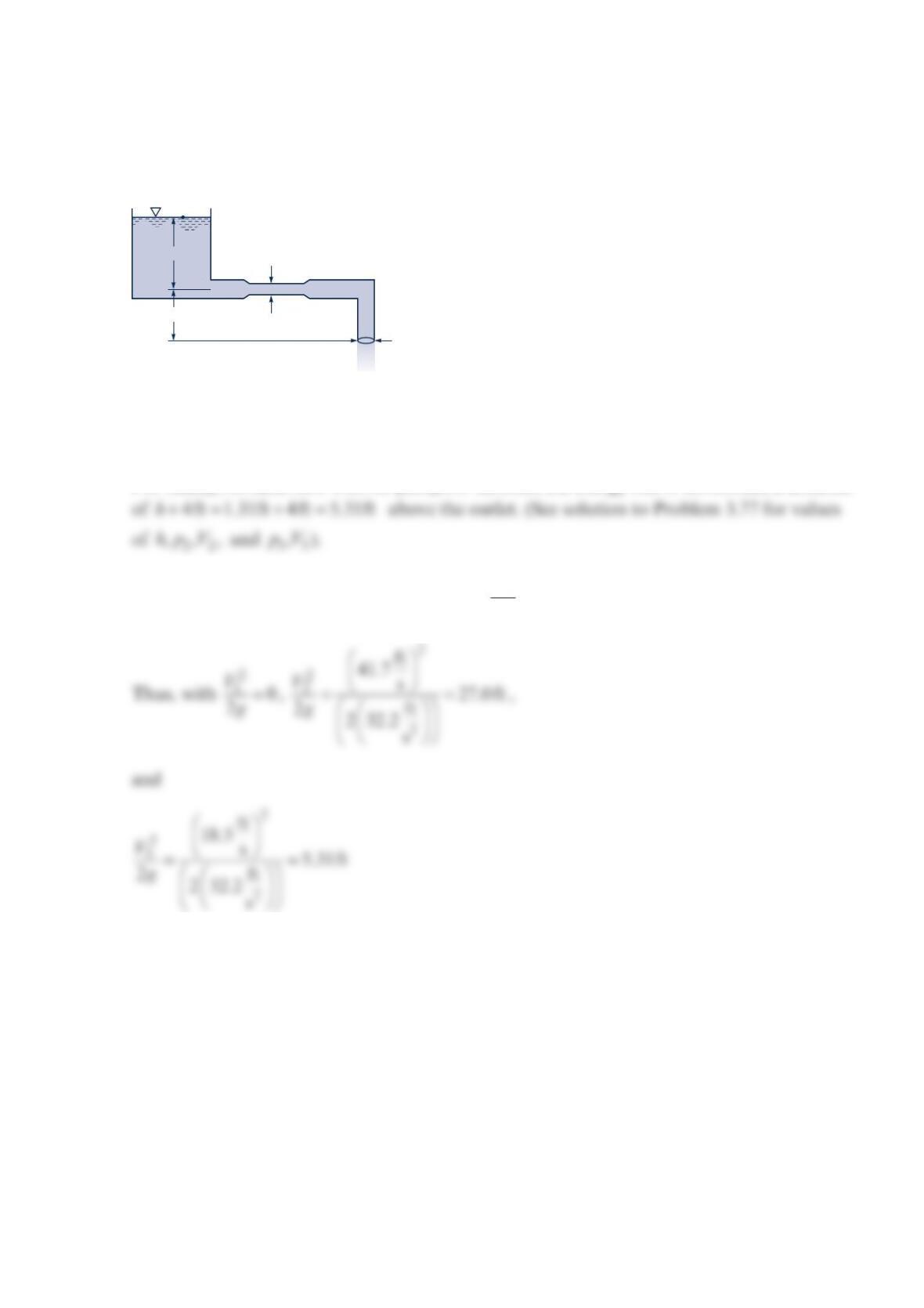
Water flows from a large tank as shown in the figure below. Atmospheric pressure is
14.5psia . Draw the energy line and the hydraulic grade line for the flow.
Solution 3.134
For inviscid flow with no pumps or turbines, the energy line is horizontal, a distance h
above the outlet. From Problem 3.90, we obtain 1.79fth=.
D
3 = 4 in.
D
1 = 1 in.
D
2 = 2 in.
h
(0)
(2)
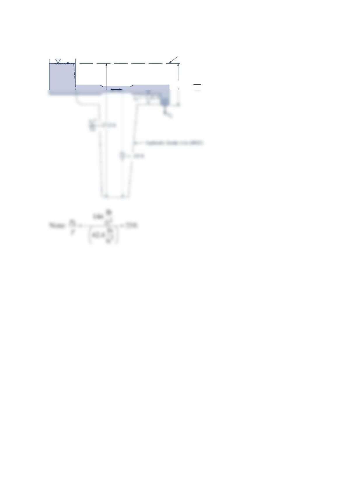
The corresponding EL and HGL are drawn to scale below.
(3)
(0) Energy Line (
EL
)
(1) (2)
2
g
V
3
2
= 0.112 ft
z
= 0
Problem 3.135
Water flows steadily with negligible viscous effects through the pipe shown in the figure be-
low. Draw the energy line and hydraulic grade line for the flow.
Solution 3.135
For steady, inviscid flow with no pumps or turbines the energy line is horizontal, a distance
The hydraulic grade line is one velocity head,
2
2
V
g, below the energy line.
4-in.-diameter thin-walled tubing
6 in.
h
4 ft
(1)
(2)
(3)
The following EL and HGL are obtained:
(1)
(2)
Energy Line (
EL
)
2
g
V
3
2
5.31 ft =
V
2
z
2
= 0
Problem 3.137
The following table lists typical flight speeds for two aircraft. For which of these conditions
would it be reasonable to use the incompressible Bernoulli’s equation to study the aerody-
namics associated with their flight? Explain.
Flight speed (km/hr)
Aircraft Cruise Landing approach
Boeing 787 913 214
F-22 fighter 1960 250
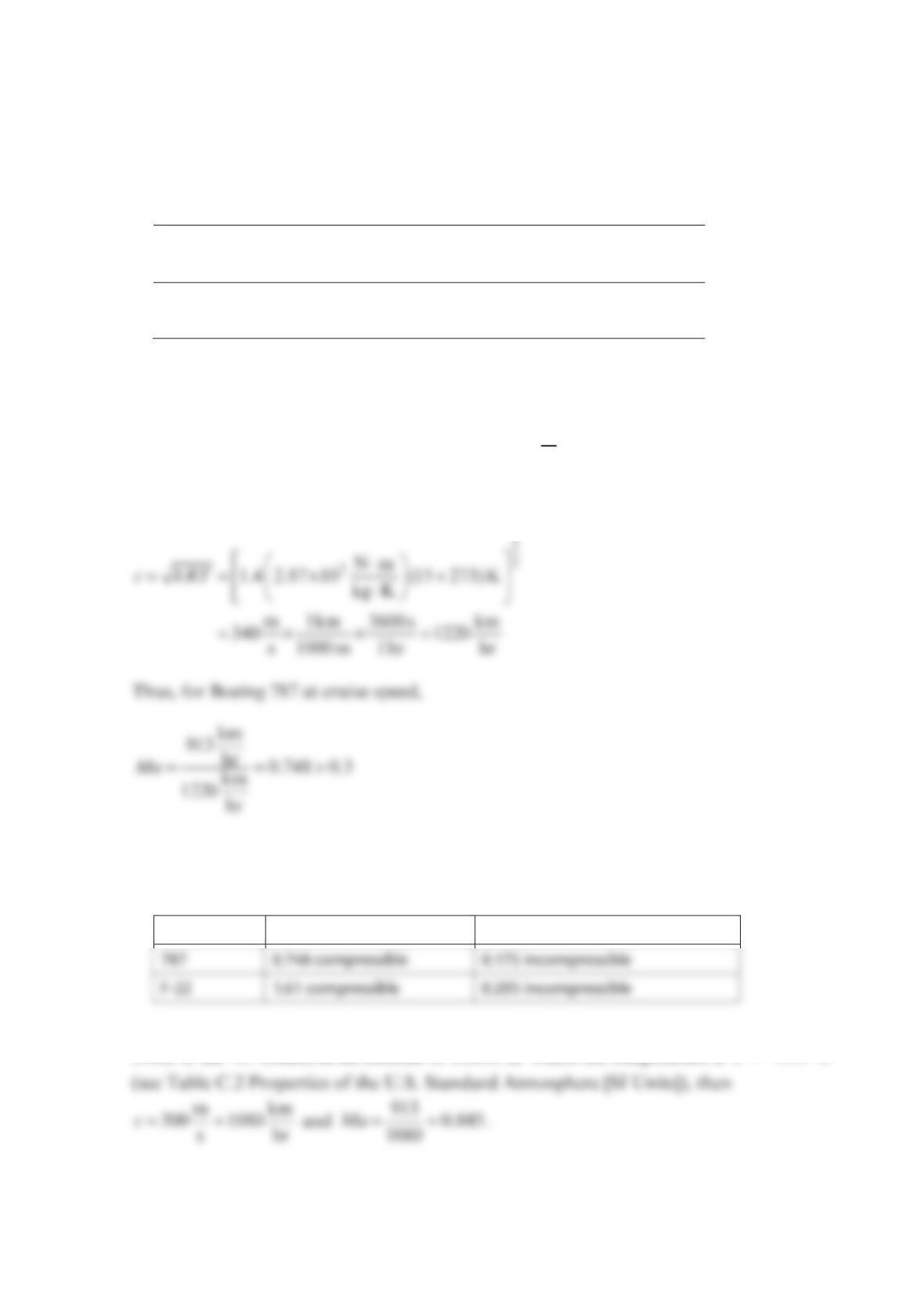
Solution 3.137
Assume incompressible equations are valid if 0.3
V
Ma c
=< .
For standard sea level conditions, 15°CT= so that
so that it is not reasonable to use incompressible analysis.
The table below gives results for the four conditions given above.
Aircraft Cruise Ma Landing approach Ma
Note: If the 787 cruises at an altitude of 10,000 m where the temperature is 49.9°CT=−
Problem 3.138
A meteorologist uses a Pitot-static tube to measure the wind speed in a tornado. Based on
the damage caused by the storm, the tornado is rated as EF5 on the Enhanced Fujita Scale.
This means that the wind speed is estimated to be in the range of 261 to 318 mph. Is it rea-
sonable to use the incompressible Pitot-tube equation [Eq. (3.16)] to determine the actual
wind speed, or must compressible effects to taken into account? Explain.
Solution 3.138
For air at standard conditions, ft
1117 s
c≈ (see Table B.3 Physical Properties of Air at
Standard Atmospheric Pressure)