Chap. 25 Foundations in Rocks and Intermediate Geomaterials
25.1 A site is underlain by a shale having the following properties and characteristics:
• Average uniaxial compressive strength of intact rock = 34 MPa
• Average RQD = 77%
• Average discontinuity spacing = 0.5 m
• Discontinuities are slightly rough, with slightly weathered walls, lengths between 3 and
10 m, and with narrow openings and no filling
• Dry, with occasional localized dampness
• Average unit weight = 24.0 kN/m3
Estimate for this shale the total RMR rating, GSI, Hoek–Brown failure criterion assuming the
rock is undisturbed, intact rock deformation modulus, rock mass deformation modulus, and the
rock mass Poisson’s ratio.
Solution
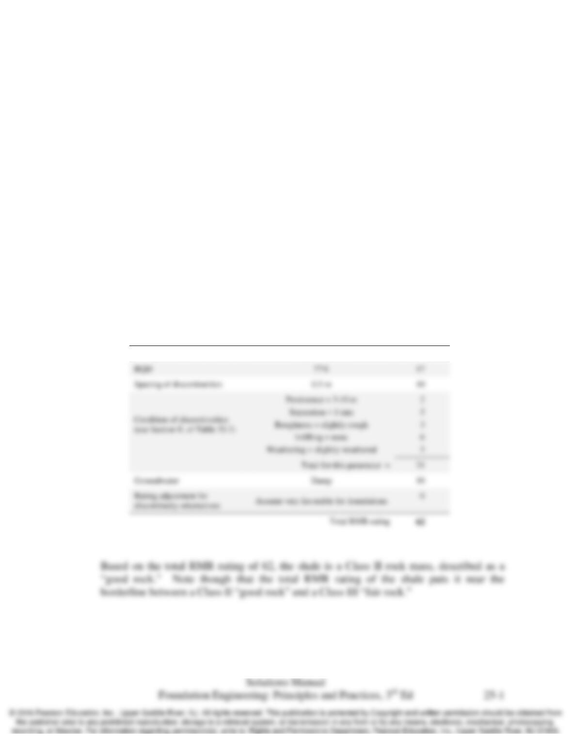
Use Table 25.2 to obtain RMR ratings for different parameters and the total RMR rating:
Parameter Value/Condition Rating
Strength of intact rock material σci = 34 MPa 4
Chap. 25 Foundations in Rocks and Intermediate Geomaterials
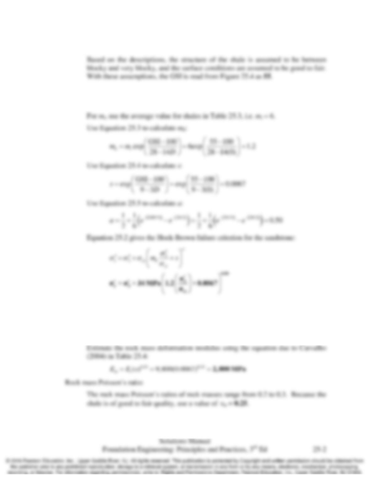
Use Figure 25.4 to estimate the GSI value for the sandstone:
Hoek-Brown failure criterion:
Because the rock mass is undisturbed, D = 0.
Intact rock deformation modulus:
Estimate the intact rock deformation modulus using Table 25.5 and mean value
for shale: Ei = 1,420 ksi or 9,800 MPa
Rock mass deformation modulus:
25.2 A site is underlain by a granite having the following properties and characteristics:
• Average uniaxial compressive strength of intact rock = 260 MPa
• Average RQD = 80%
• Average discontinuity spacing = 1.1 m
• Discontinuities are tight and rough, with slightly weathered walls and lengths between 3
and 10 m
• Dry
• Average unit weight = 25.9 kN/m3
Estimate for this granite the total RMR rating, GSI, Hoek–Brown failure criterion assuming the
rock is undisturbed, intact rock deformation modulus, rock mass deformation modulus, and the
rock mass Poisson’s ratio.
Solution
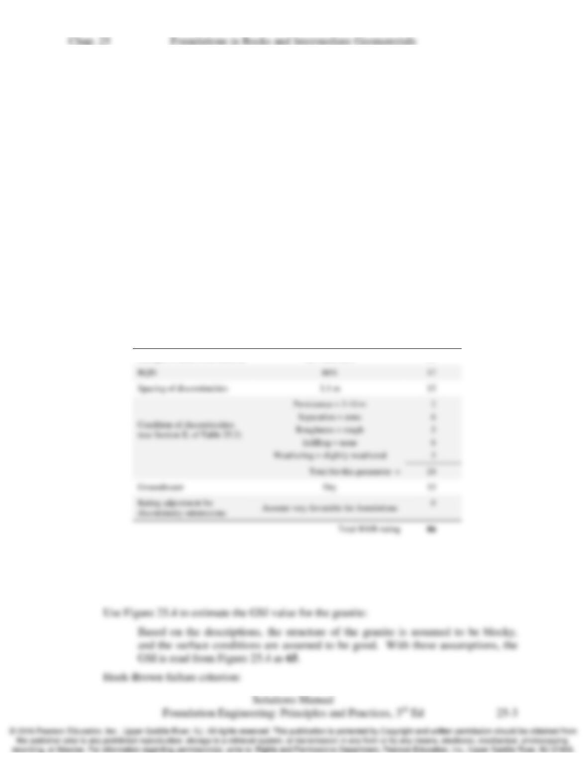
Use Table 25.2 to obtain RMR ratings for different parameters and the total RMR rating:
Parameter Value/Condition Rating
Strength of intact rock material σci = 260 MPa 15
Based on the total RMR rating of 86, the granite is a Class I rock mass, described as a
“very good rock.”
Chap. 25 Foundations in Rocks and Intermediate Geomaterials
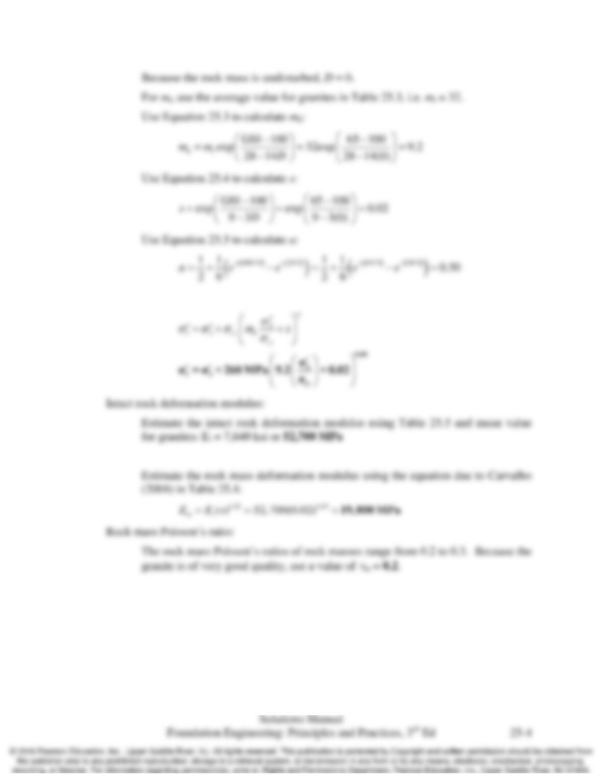
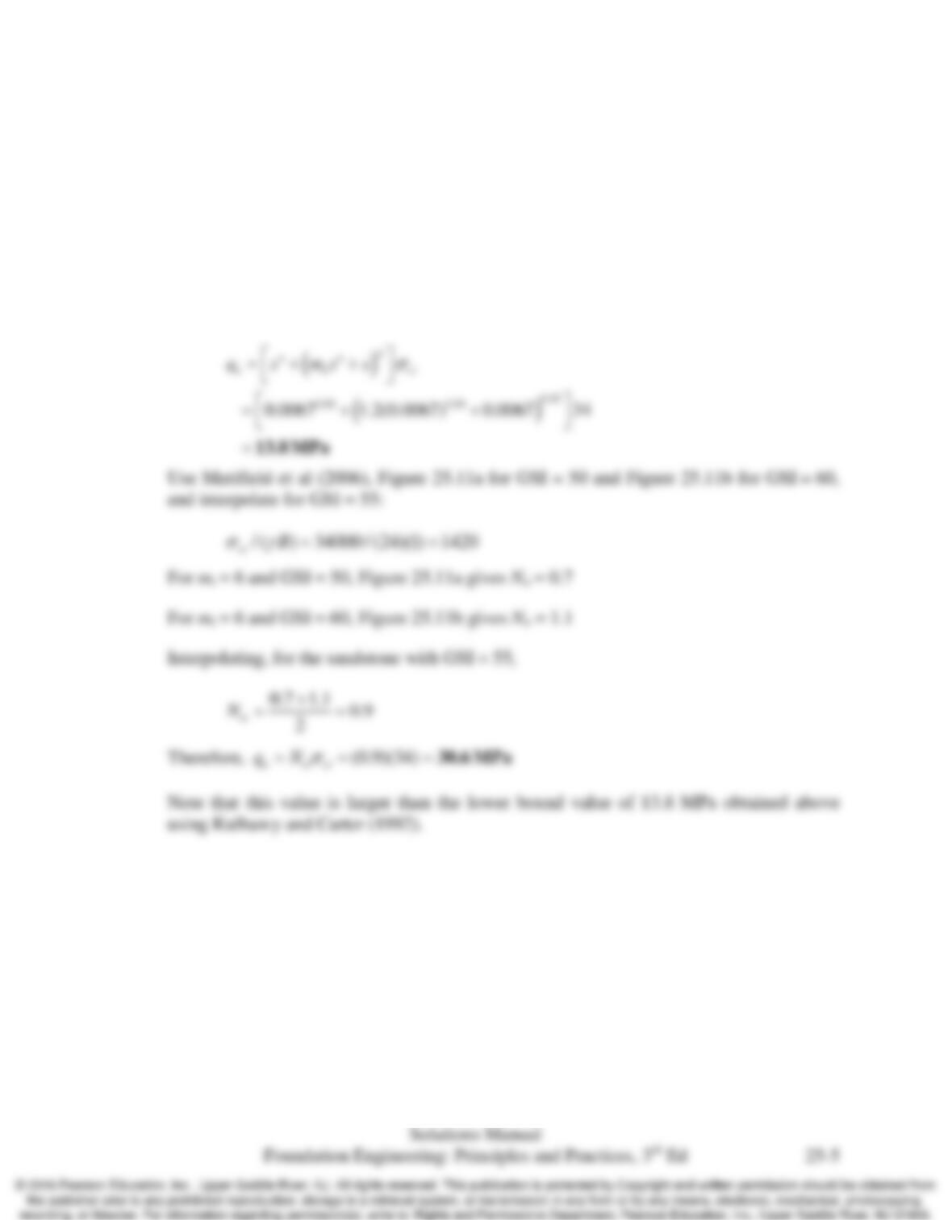
Equation 25.2 gives the Hoek-Brown failure criterion for the granite:
Rock mass deformation modulus:
Chap. 25 Foundations in Rocks and Intermediate Geomaterials
25.3 A continuous footing having a width of 1.0 m is underlain by the shale in Problem 25.1.
Estimate the nominal bearing capacity using Kulhawy and Carter (1992) and Merifield et al
(2006).
Solution
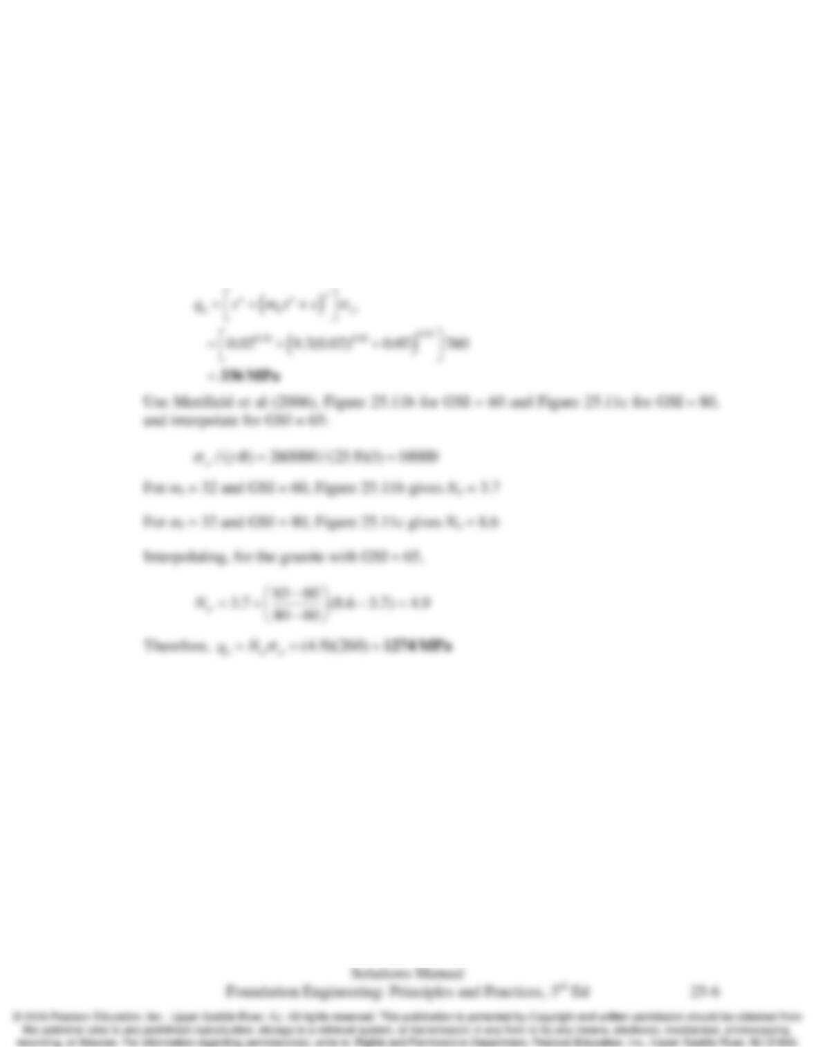
Assume rock mass behavior Type III applies and the rock mass behaves as an equivalent
continuous, isotropic material. Use Kulhaway and Carter (1992), Equation 25.7:
Chap. 25 Foundations in Rocks and Intermediate Geomaterials
25.4 A continuous footing having a width of 1.0 m is underlain by the granite in Problem 25.2.
Estimate the nominal bearing capacity using Kulhawy and Carter (1992) and Merifield et al
(2006).
Solution
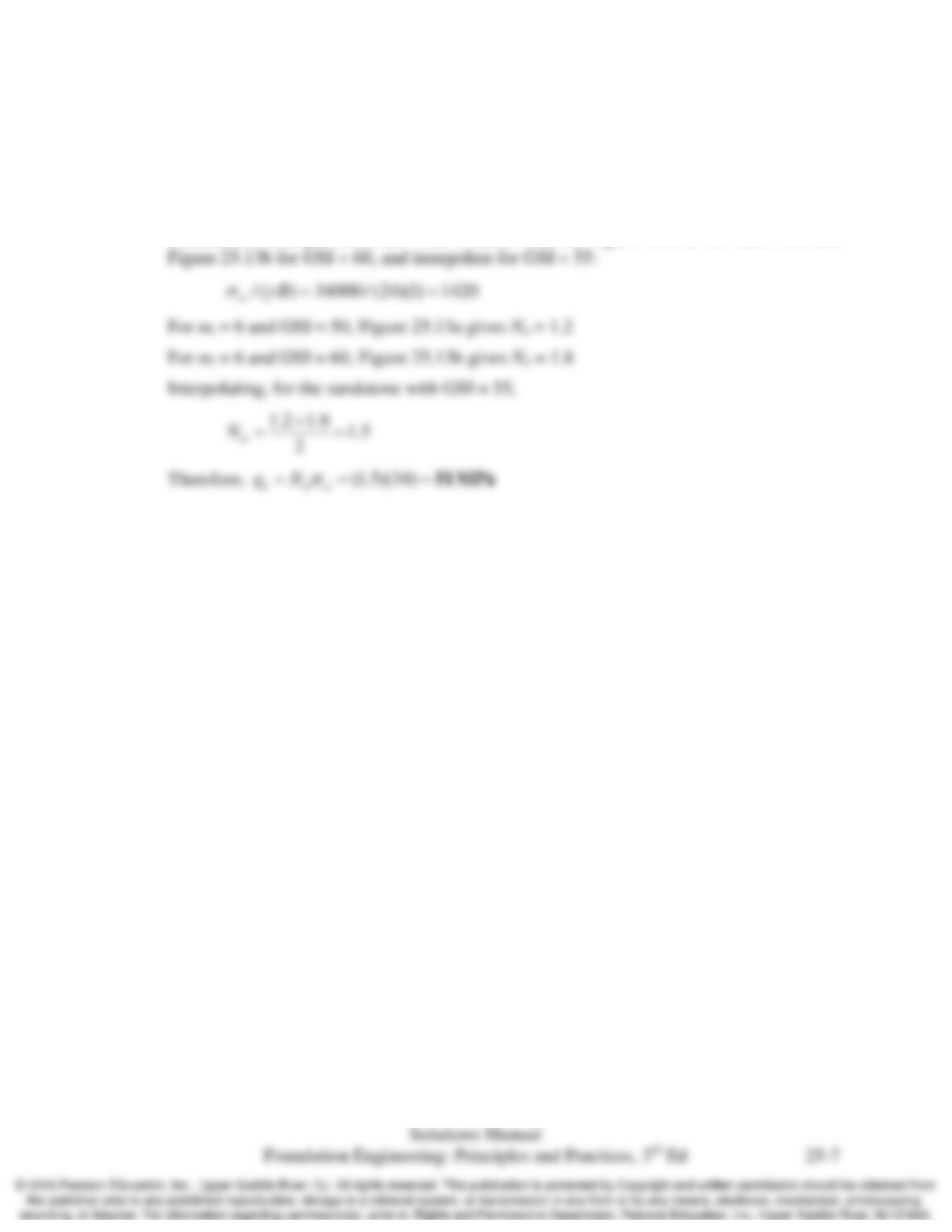
Assume rock mass behavior Type III applies and the rock mass behaves as an equivalent
continuous, isotropic material. Use Kulhaway and Carter (1992), Equation 25.7:
Note that this value is larger than the lower bound value of 336 MPa obtained above
using Kulhawy and Carter (1992).
Chap. 25 Foundations in Rocks and Intermediate Geomaterials
25.5 A circular footing having a diameter of 1.0 m is underlain by the shale in Example 25.1.
Estimate the nominal bearing capacity using Clausen (2013).
Solution
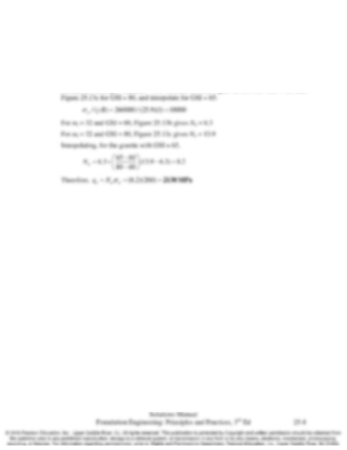
Assume rock mass behavior Type III applies and the rock mass behaves as an equivalent
continuous, isotropic material. Use Clausen (2013), Figure 25.13a for GSI = 50 and
Chap. 25 Foundations in Rocks and Intermediate Geomaterials
25.6 A circular footing having a diameter of 1.0 m is underlain by the granite in Example 25.2.
Estimate the nominal bearing capacity using Clausen (2013).
Solution
Assume rock mass behavior Type III applies and the rock mass behaves as an equivalent
continuous, isotropic material. Use Clausen (2013), Figure 25.13b for GSI = 60 and
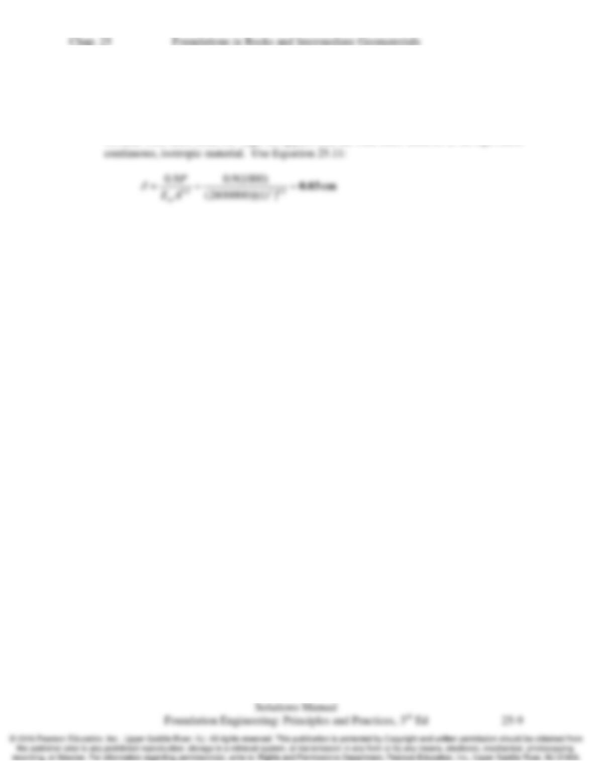
25.7 A square footing having a width of 1.0 m is underlain by the shale in Problem 25.1. Estimate the
settlement under a vertical downward sustained load of 1,000 kN.
Solution
Assume rock mass behavior Type III applies and the rock mass behaves as an equivalent
Chap. 25 Foundations in Rocks and Intermediate Geomaterials
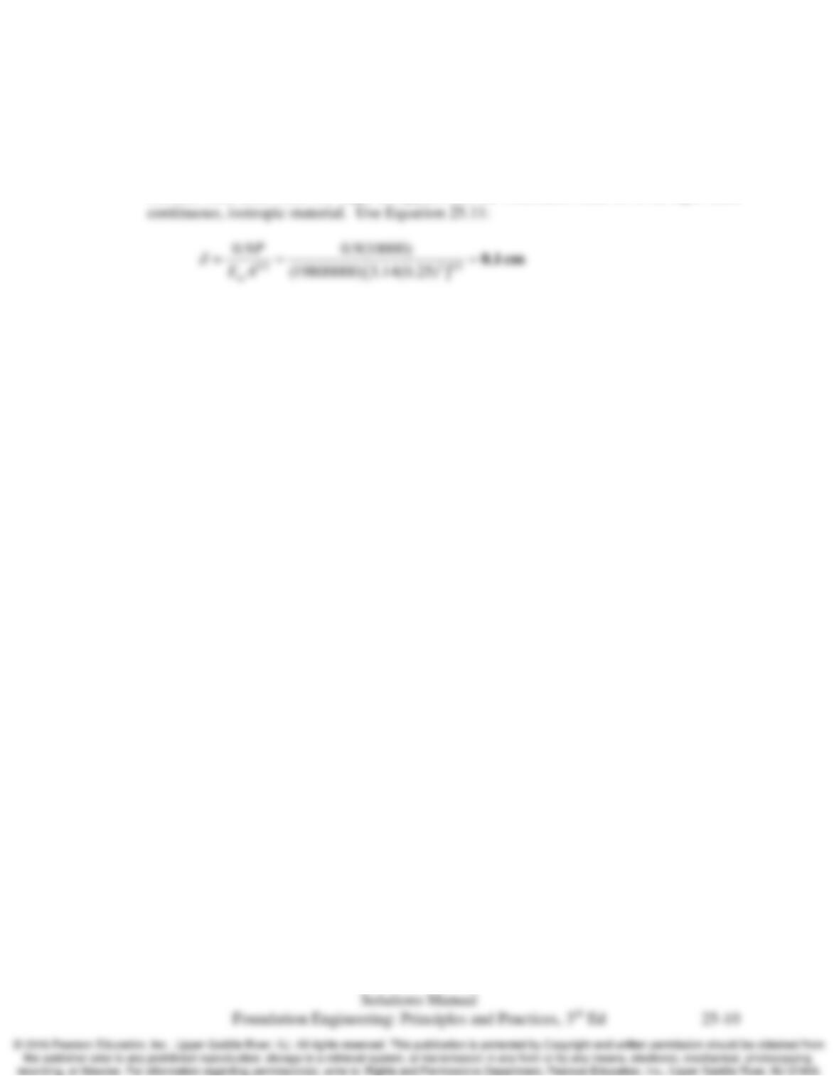
25.8 A circular footing having a diameter of 500 mm is underlain by the granite in Problem 25.2.
Estimate the settlement under a vertical downward sustained load of 10,000 kN.
Solution
Assume rock mass behavior Type III applies and the rock mass behaves as an equivalent
Chap. 25 Foundations in Rocks and Intermediate Geomaterials
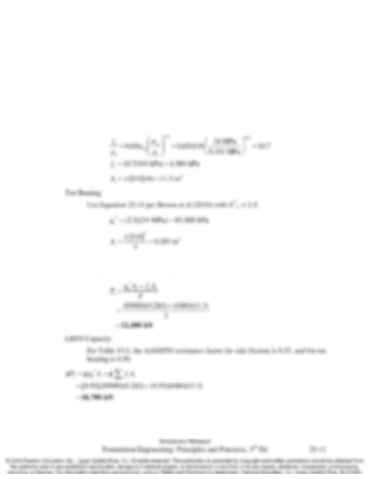
25.9 A rock socketed pile is to be designed without the benefit of any onsite static load tests. The
ground conditions are uniform, and the site characterization program was average. For a 600
mm diameter drilled shaft, fully socketed in rock from the ground surface to a depth of 6 m in the
shale in Problem 25.1, compute the ASD allowable compressive load capacity and the AASHTO
LRFD factored compressive load capacity.
Solution
Side Friction
Use Equation 25.13 per O’Neill and Reese (1999). For RQD = 77%, Table 25.7
gives
a
E = 0.9. Therefore
ASD Capacity
Using a factor of safety of 3 (per Table 13.2):
Chap. 25 Foundations in Rocks and Intermediate Geomaterials
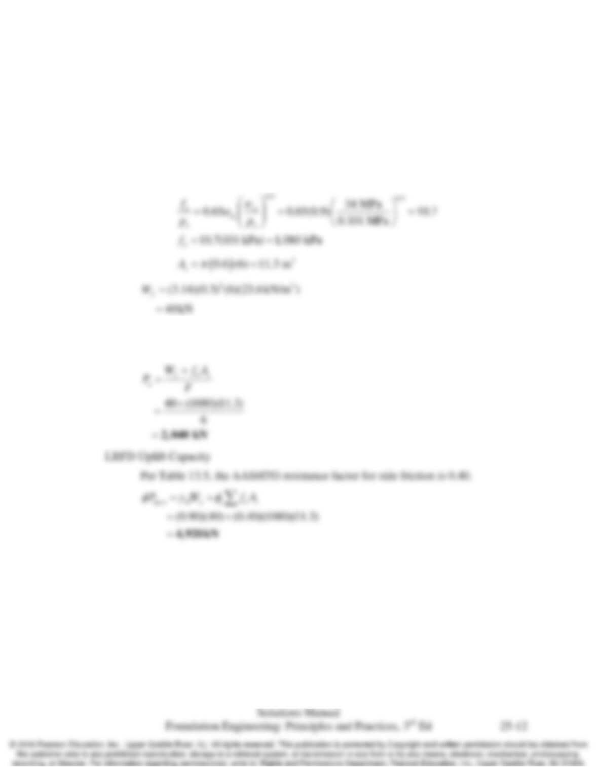
25.10 Using the data in Problem 25.9, compute the ASD upward load capacity and the AASHTO
upward load capacity,
,up n
P
f
. Use a load factor of 0.9 on the weight of the shaft.
Solution
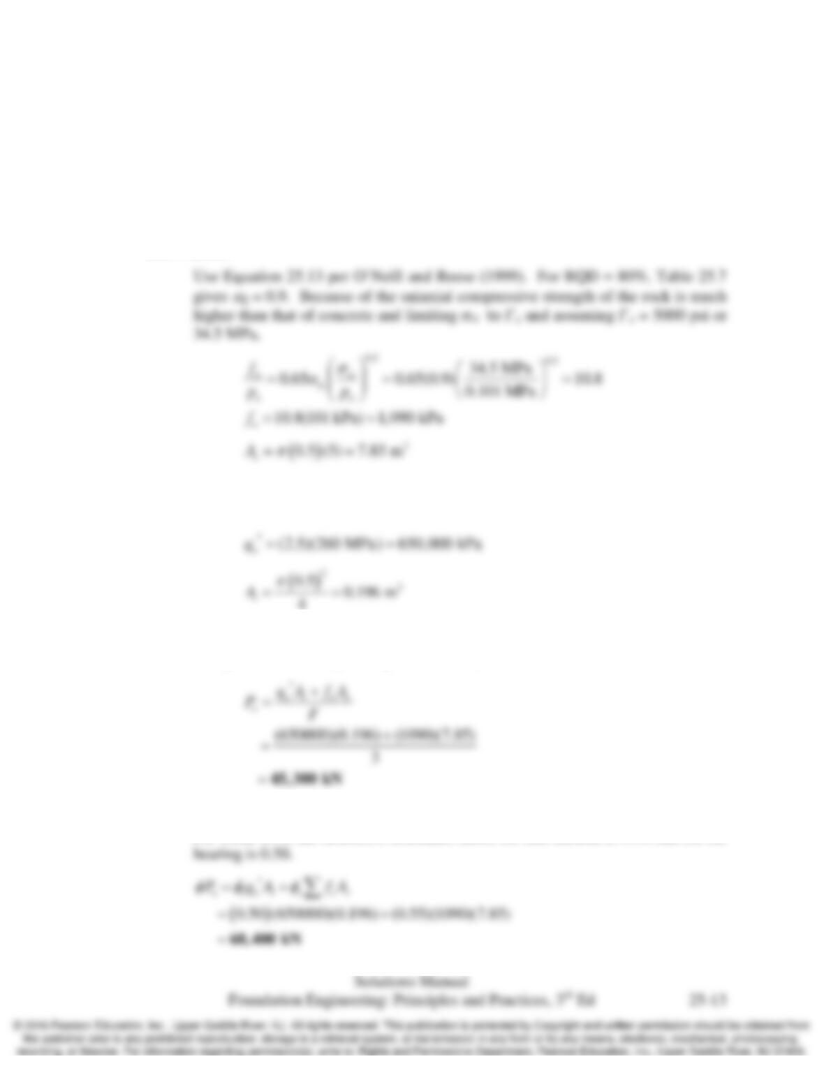
Side Friction
Use Equation 25.13 per O’Neill and Reese (1999). For RQD = 77%, Table 25.7
gives
a
E = 0.9. Therefore
ASD Uplift Capacity
Using a factor of safety of 6 (per Table 13.2):
Chap. 25 Foundations in Rocks and Intermediate Geomaterials
25.11 A rock socketed pile is to be designed without the benefit of any onsite static load tests. The
ground conditions are uniform, and the site characterization program was average. For a 500
mm diameter drilled shaft, fully socketed in rock from the ground surface to a depth of 5 m in the
granite in Problem 25.2, compute the ASD allowable compressive load capacity and the
AASHTO LRFD factored compressive load capacity.
Solution
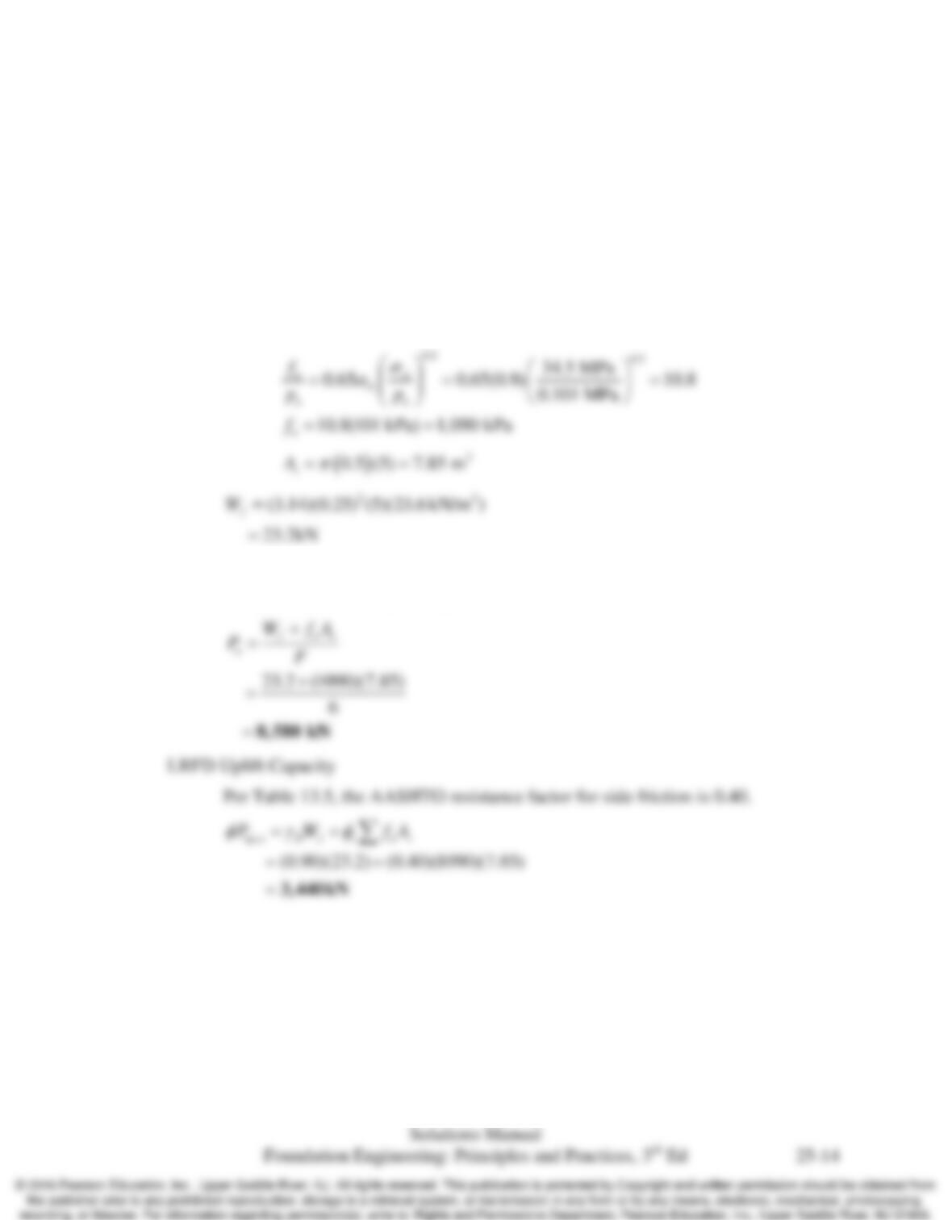
Side Friction
Toe Bearing
Use Equation 25.14 per Brown et al (2010) with N*cr = 2.5:
4
ASD Capacity
Using a factor of safety of 3 (per Table 13.2):
LRFD Capacity
Per Table 13.5, the AASHTO resistance factor for side friction is 0.55, and for toe
Chap. 25 Foundations in Rocks and Intermediate Geomaterials
25.12 Using the data in Problem 25.10, compute the ASD upward load capacity and the AASHTO
upward load capacity,
,up n
P
f
. Use a load factor of 0.9 on the weight of the shaft.
Solution
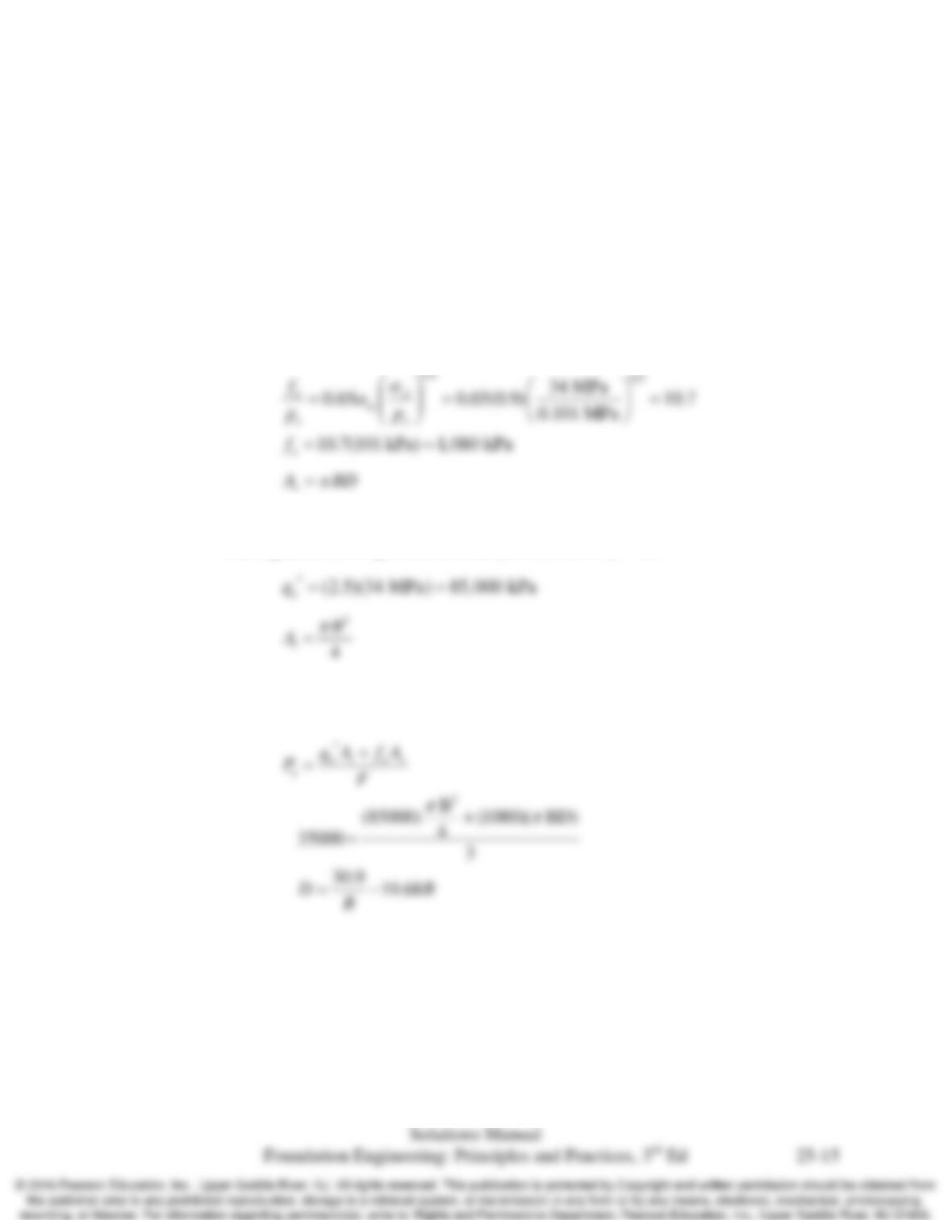
Side Friction
Use Equation 25.13 per O’Neill and Reese (1999). For RQD = 80%, Table 25.7
gives
a
E = 0.9. Because of the uniaxial compressive strength of the rock is much
higher than that of concrete and limiting σci to f’c and assuming f’c = 5000 psi or
34.5 MPa,
ASD Uplift Capacity
Using a factor of safety of 6 (per Table 13.2):
Chap. 25 Foundations in Rocks and Intermediate Geomaterials
25.13 A site is underlain by the shale in Problem 25.1 with the shale exposed at the surface. Determine
the required diameter and length of a drilled shaft needed to support an ASD design downward
load of 35,000 kN. Note there are many different diameter–length combinations that would be
satisfactory, but select one that you think would be most appropriate.
Solution
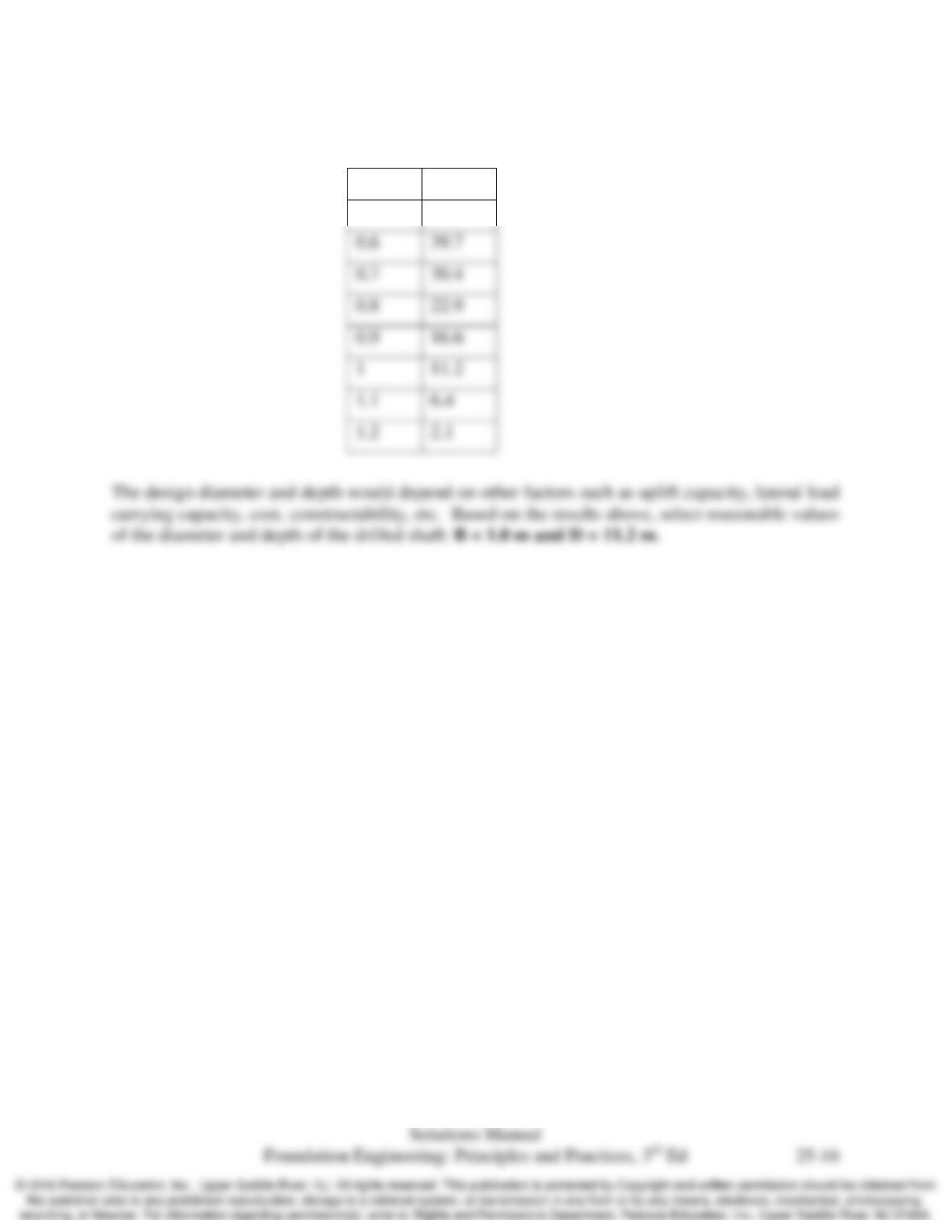
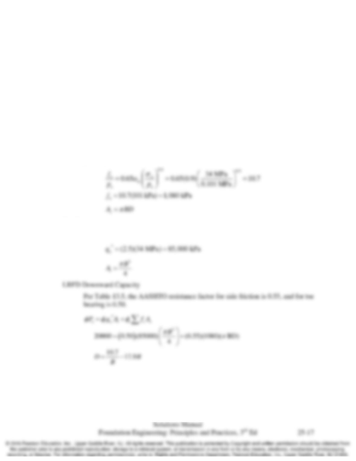
Let the diameter and depth of the drilled shaft be B and D, respectively.
Side Friction
Use Equation 25.13 per O’Neill and Reese (1999). For RQD = 77%, Table 25.7
gives
a
E = 0.9. Therefore
Toe Bearing
Use Equation 25.14 per Brown et al (2010) with N*cr = 2.5:
ASD Capacity
Using a factor of safety of 3 (per Table 13.2):
Chap. 25 Foundations in Rocks and Intermediate Geomaterials
Try different combinations of B and D values that would work:
B (m)
D (m)
0.5
52.0
0.6
39.7
0.7
30.4
0.8
22.9
0.9
16.6
1
11.2
1.1
6.4
1.2
2.1
Chap. 25 Foundations in Rocks and Intermediate Geomaterials
25.14 A drilled shaft designed in accordance with the AASHTO code must support the following
downward and uplift axial design loads: Pu = 20,000 kN, Pup,u = 7,000 kN. The site is underlain
by the shale in Problem 25.1 from the ground surface down to great depths. Using the AASHTO
resistance factors, select a diameter and depth for a single drilled shaft to support these design
loads. Use a load factor of 0.9 on the weight of the shaft. Note there are many different
diameter–length combinations that would be satisfactory, but select one that you think would be
most appropriate.
Solution
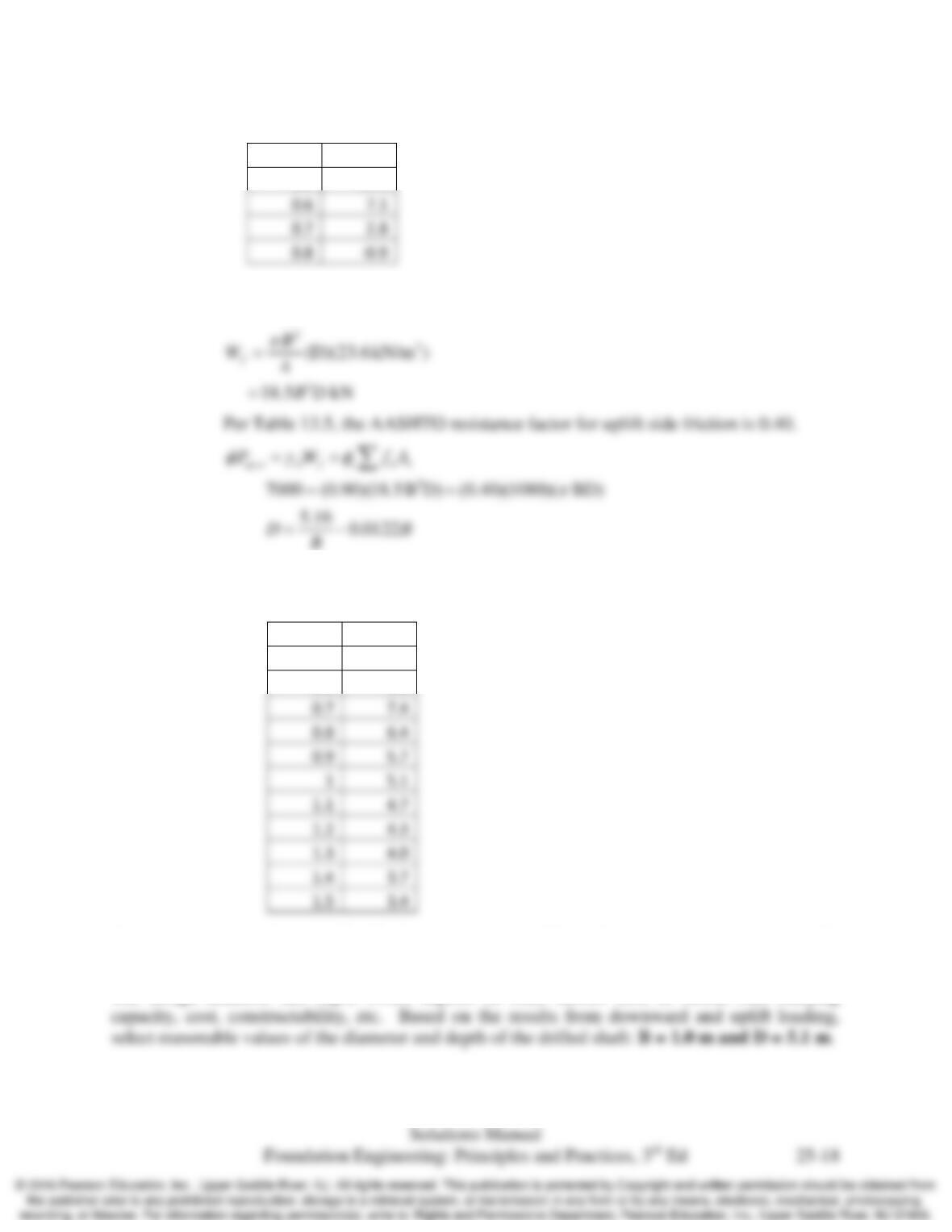
Let the diameter and depth of the drilled shaft be B and D, respectively.
Side Friction
Use Equation 25.13 per O’Neill and Reese (1999). For RQD = 77%, Table 25.7
gives
a
E = 0.9. Therefore
Toe Bearing
Use Equation 25.14 per Brown et al. (2010) with N*cr = 2.5:
Chap. 25 Foundations in Rocks and Intermediate Geomaterials
Try different combinations of B and D values that would work:
B (m)
D (m)
0.5
12.5
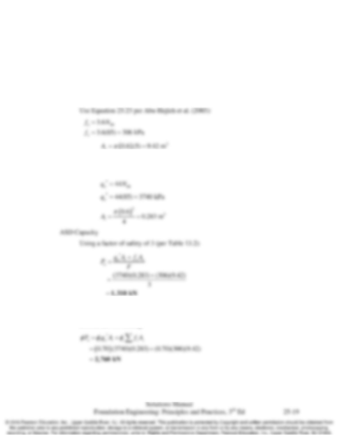
LRFD Uplift Capacity
Try different combinations of B and D values that would work:
0.7
0.8
0.9
1.1
1.2
4.3
1.3
1.4
1.5
Combining the requirements for the downward and uplift loading, it can be seen that uplift
controls the design.
The design diameter and depth would depend on other factors such as lateral load carrying
B (m)
D (m)
0.5
10.3
0.6
8.6
0.6
7.1
0.7
0.8
Chap. 25 Foundations in Rocks and Intermediate Geomaterials
25.15 A rock socketed pile is to be designed without the benefit of any onsite static load tests. The
ground conditions are uniform, and the site characterization program was average. For a 600
mm diameter drilled shaft, fully socketed in a cohesive IGM having an average SPT N60–value of
85, from the ground surface to a depth of 5 m, compute the ASD allowable compressive load
capacity and the LRFD factored compressive load capacity.
Solution
Side Friction
s
Toe Bearing
Use Equation 25.24 per Abu-Hejleh et al. (2003):
LRFD Capacity
Abu–Hejleh et al. (2003) recommends a resistance factor of 0.70 for both side
friction and toe bearing.