
Chap. 22 Laterally Loaded Piles
22.1 What are the primary advantages of using laterally–loaded vertical piles instead of battered piles?
Solution
Contractors with the proper equipment can usually install them at a batter as steep as 4 vertical to

Chap. 22 Laterally Loaded Piles
22.2 Explain the difference between short piles and long piles.
Solution
A short pile is one that does not have enough embedment depth to anchor the toe against rotation,
whereas a long pile is one in which the toe is embedded deeply enough to be essentially fixed
against any rotation or lateral displacement. The minimum length required to be considered
Chap. 22 Laterally Loaded Piles
22.3 A static lateral load test has been conducted on an HP 10×57 pile made of steel with fy = 50 k/in2.
The lateral load was applied so that bending occurred in the strong axis. According to
measurements made during this test, the lateral deflection between the ground surface and a
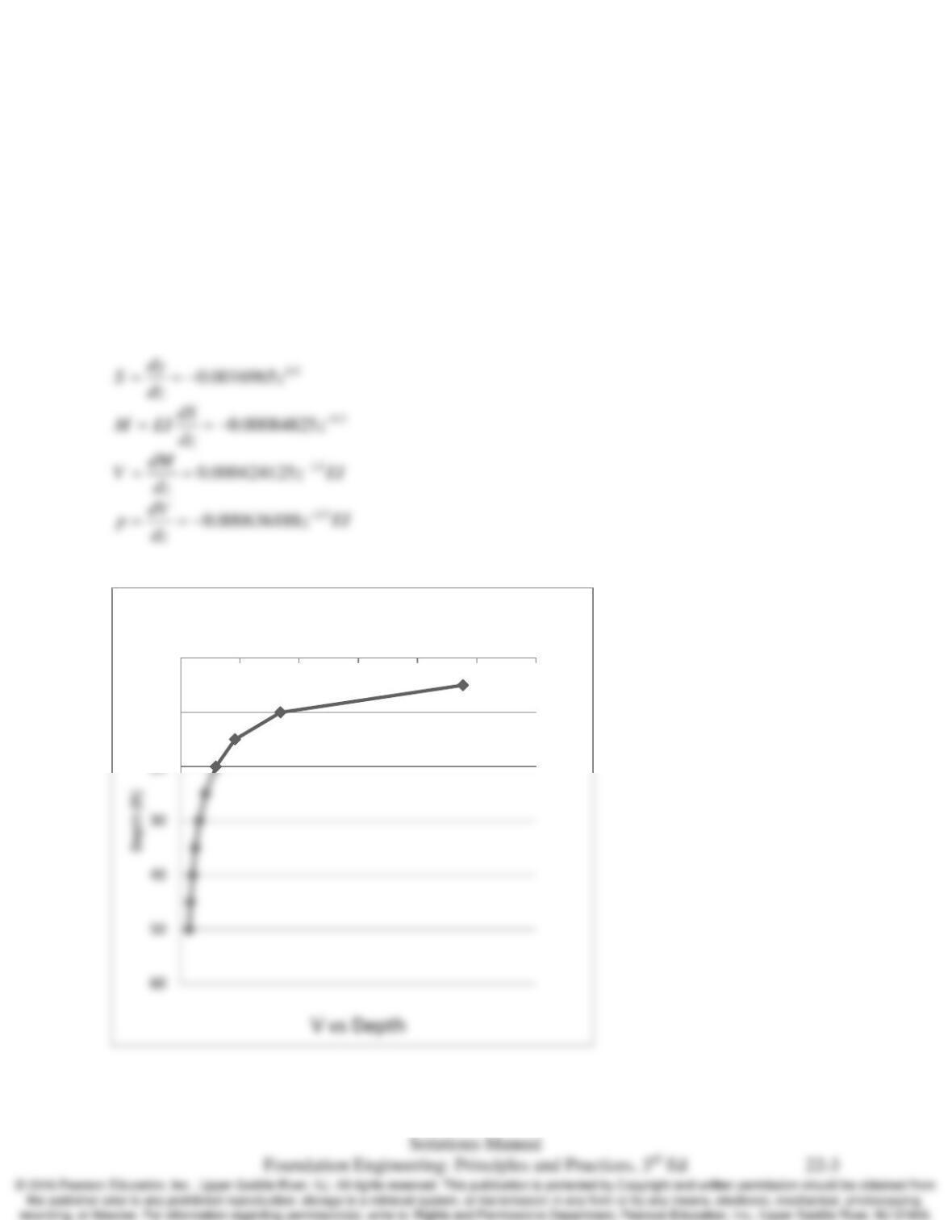
depth of 10 ft is defined by the equation y = 1.52 – 0.001131 z1.5 , where both y and z are
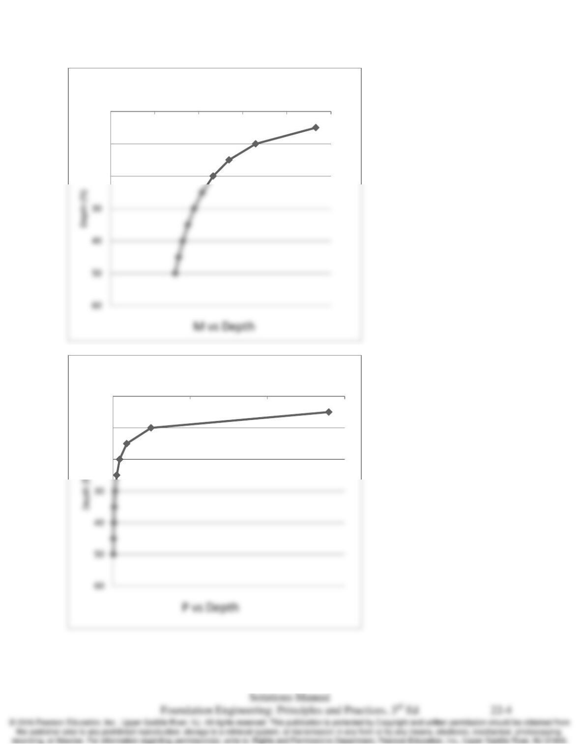
expressed in inches. Develop plots of shear, moment, and lateral soil pressure vs. depth.
Solution
2234
( ) = 8,526,000,00EI = (29,000,000 lb/i 0 lb/i 1.228x10 ^n ) 12 2 l94 in n b/ft=
Plot M, V and P vs depth.
0
10
20
010 20 30 40 50 60
V (lb x 106)
Chap. 22 Laterally Loaded Piles
0
10
20
-500-400-300-200-1000
M (ft–lb x 106)
0
10
20
-15-10-50
P (lb x 106)

Chap. 22 Laterally Loaded Piles
22.4 Explain the difference between a rigid analysis and a nonrigid analysis.
Solution
Thus, rigid analyses are used primarily for single isolated piles where the axial load is modest,
the lateral load dictates the required depth of embedment, and lateral deflection does not control
Chap. 22 Laterally Loaded Piles
22.5 A group of cell–phone antennas are to be installed on a single steel pole that will be embedded
into a dense silty sand with
35
φ
′=
. Near the ground surface this pole will be connected to a 24
inch diameter drilled shaft. The resultant of the lateral wind load will be 600 lb and will act at a
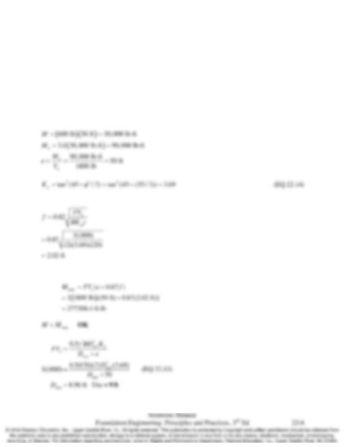
point 50 ft above the ground surface. Using a rigid analysis, compute the required depth of
embedment and the maximum moment in the drilled shaft. Use a factor of safety of 3.0.
Solution
*Assume soil unit weight = 120 pcf *
Mmax is:

Chap. 22 Laterally Loaded Piles
Where:
Chap. 22 Laterally Loaded Piles
22.6 A large sign is to be supported on two steel poles, each of which will be supported by an 18-inch
diameter drilled shaft. The lateral wind load acting on the sign will be 3000 lb and distributed
evenly between the two piles. The centroid of this wind load will be 30 ft above the ground
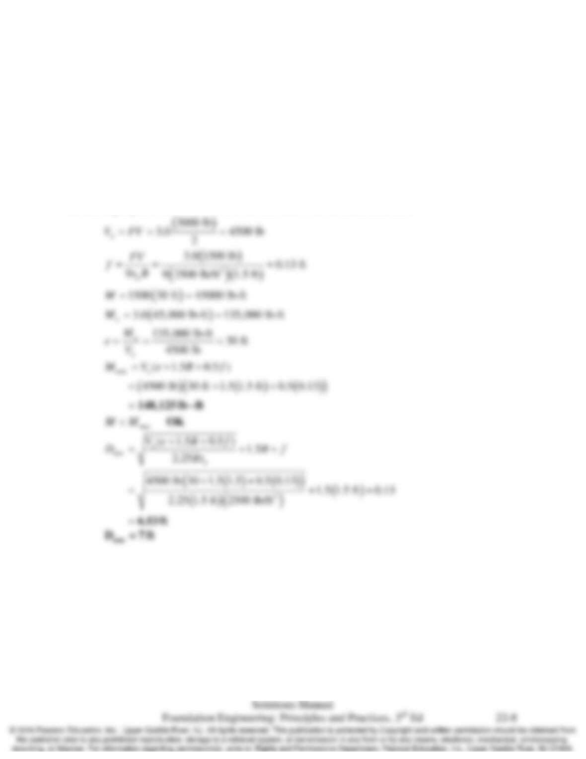
surface. The soils are sandy clays with su = 2500 lb/ft2. Using a rigid analysis, compute the
required depth of embedment and the maximum moment in each drilled shaft. Use a factor of
safety of 3.0.
Solution
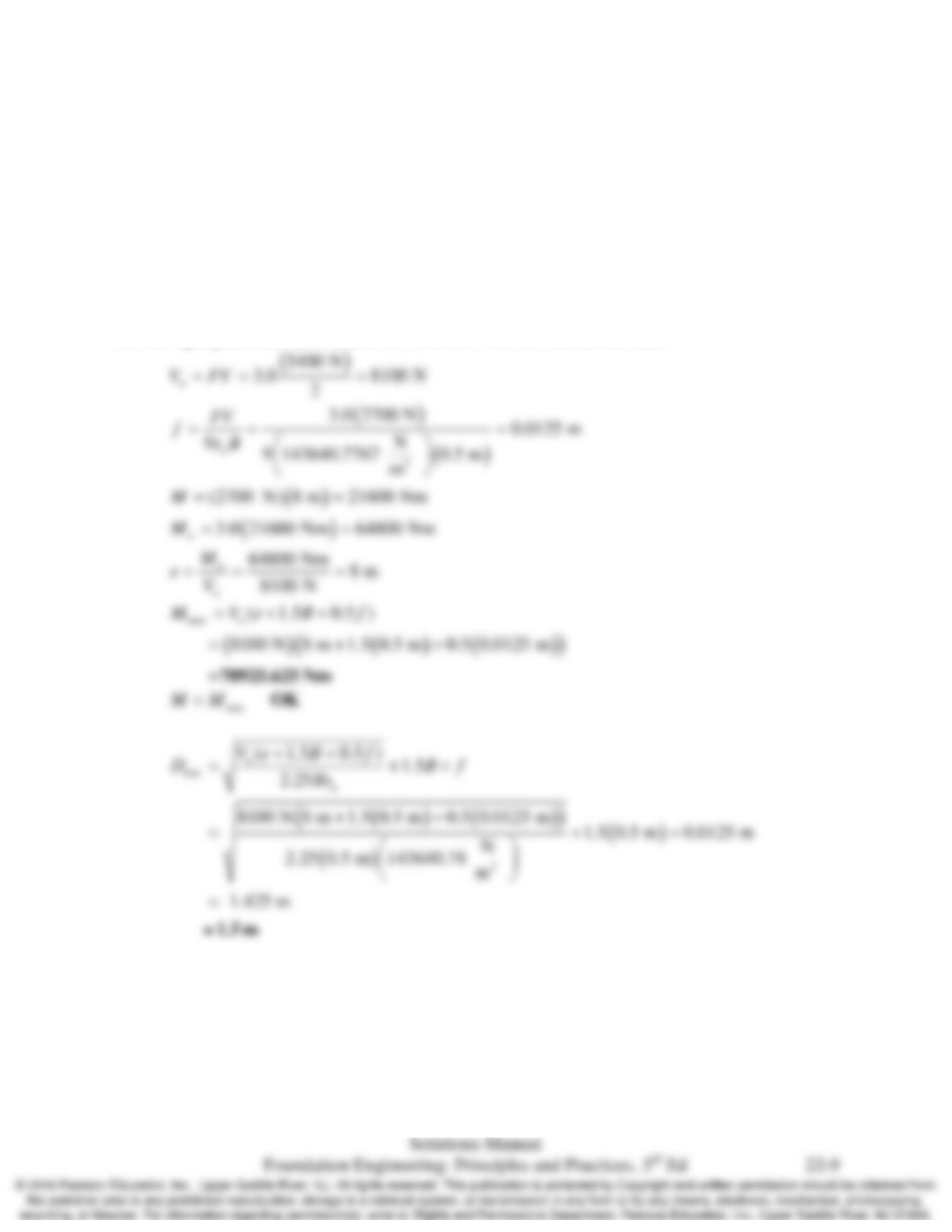
Use the rigid pile, free head method for cohesive soils for one drilled shaft.
Chap. 22 Laterally Loaded Piles
22.7 A large sign is to be supported on two steel poles, each of which will be supported by a 500 mm
diameter drilled shaft embedded into a stiff silty clay. The lateral wind load will be 5.4 kN and
will act at a height of 8 m above the ground surface. This load will be equally distributed to the
two poles. Using a rigid analysis compute the required depth of embedment and the maximum
moment in each drilled shaft. Use a factor of safety of 3.0.
Solution
*Assume an undrained strength = 3000 psf*
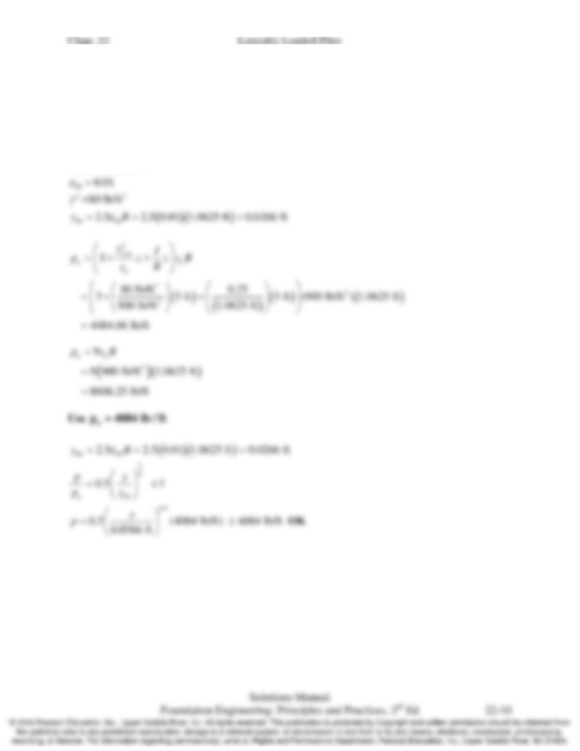
Use the rigid pile, free head method for cohesive soils for one drilled shaft.
22.8 A 12.75 inch diameter steel pipe pile is driven into a saturated medium clay with su = 900 lb/ft2
and γʹ = 80 lb/ft3. This pile is embedded to a depth great enough to be considered a long pile.
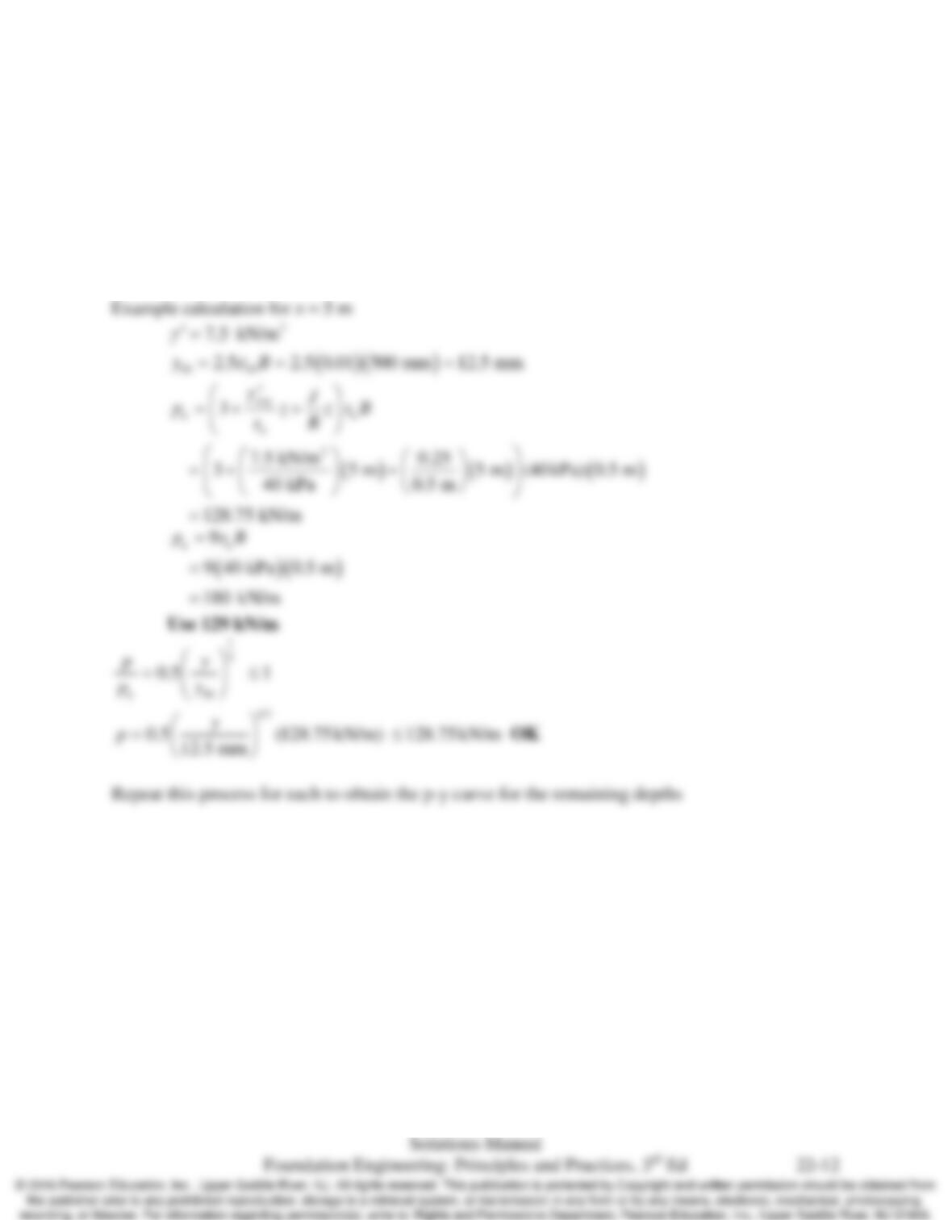
Using a spreadsheet, develop a family of p-y curves at depths of 5, 10, 15, and 20 ft using
Matlock. Plot all four curves on the same diagram.
Solution
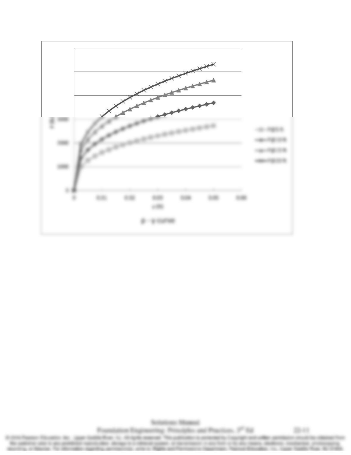
From Table 22.1:
Chap. 22 Laterally Loaded Piles
4000
5000
6000
Chap. 22 Laterally Loaded Piles
22.9 A 500 diameter steel pipe pile is driven into a saturated medium clay with su = 40 kPa and
γ
′=
7.5 kN/m3. This pile is embedded to a depth great enough to be considered a long pile. Using a
spreadsheet, develop a family of p-y curves at depths of 1, 2, 3, 4, and 5 m using Matlock. Plot
all five curves on the same diagram.
Solution
From Table 22.1:
50 0.01
ε
=
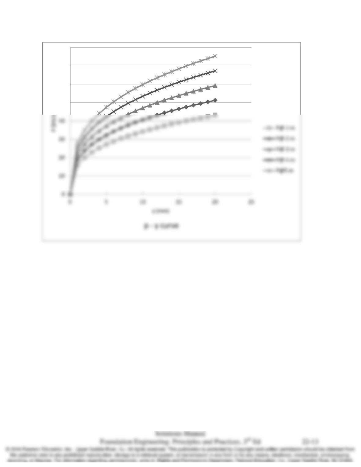
Chap. 22 Laterally Loaded Piles
50
60
70
80
Chap. 22 Laterally Loaded Piles
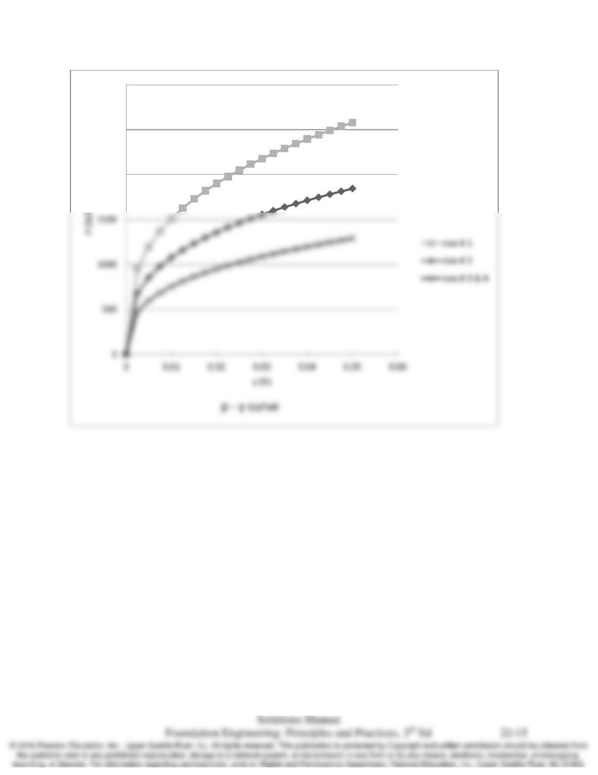
22.10 Sixteen of the piles described in Problem 22.8 are to be installed in a 4×4 group. Using the
computed p-y curve for an isolated single pile (from Problem 22.8) and the appropriate p
multipliers, develop the p-y curves for the first, second, third, and fourth row of this pile group at
a depth of 10 ft.
Solution
*Assume a center – center spacing = 3B *
Chap. 22 Laterally Loaded Piles
2000
2500
3000
Chap. 22 Laterally Loaded Piles
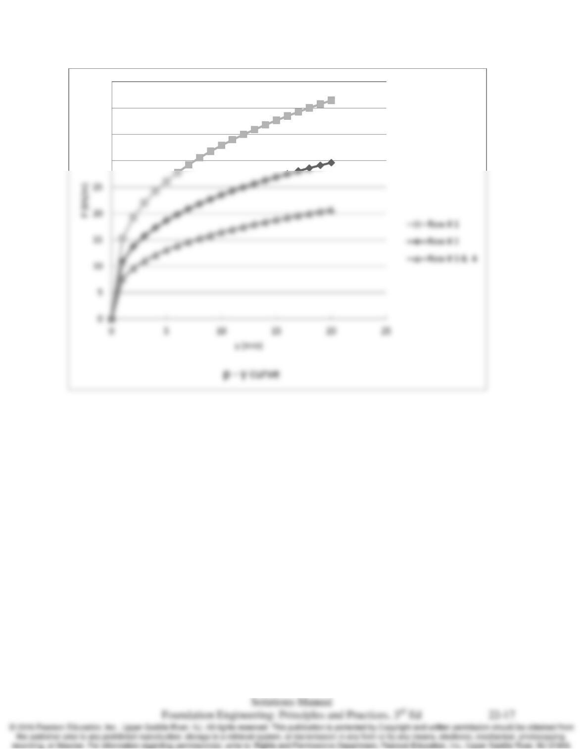
22.11 Sixteen of the piles described in Problem 22.9 are to be installed in a 4×4 group. Using the
computed p-y curve for an isolated single pile (from Problem 22.9) and the appropriate p
multipliers, develop the p-y curves for the first, second, third, and fourth row of this pile group at
a depth of 3 m.
Solution
1
3
50
1/3
0.5 1
0.5 (101.25kN/m) (101.25kN/m)
12.5 mm
mu
um
py
pp y
y
p pp
= ≤
= ≤
OK
Chap. 22 Laterally Loaded Piles
30
35
40
45