Chap. 21 Piles: Structural Design
21.1 Why is it appropriate to use more conservative structural designs for foundations than for
comparable superstructure members?
Solution
• The construction tolerances for piles are much wider and quality control is more difficult.
• Piles are often constructed slightly off their planned location, which introduces unplanned

Chap. 21 Piles: Structural Design
21.2 What type of pile is least prone to damage during handling?
Solution

Chap. 21 Piles: Structural Design
21.3 What is the most common yield strength of steel used for steel piles?
Solution
Chap. 21 Piles: Structural Design
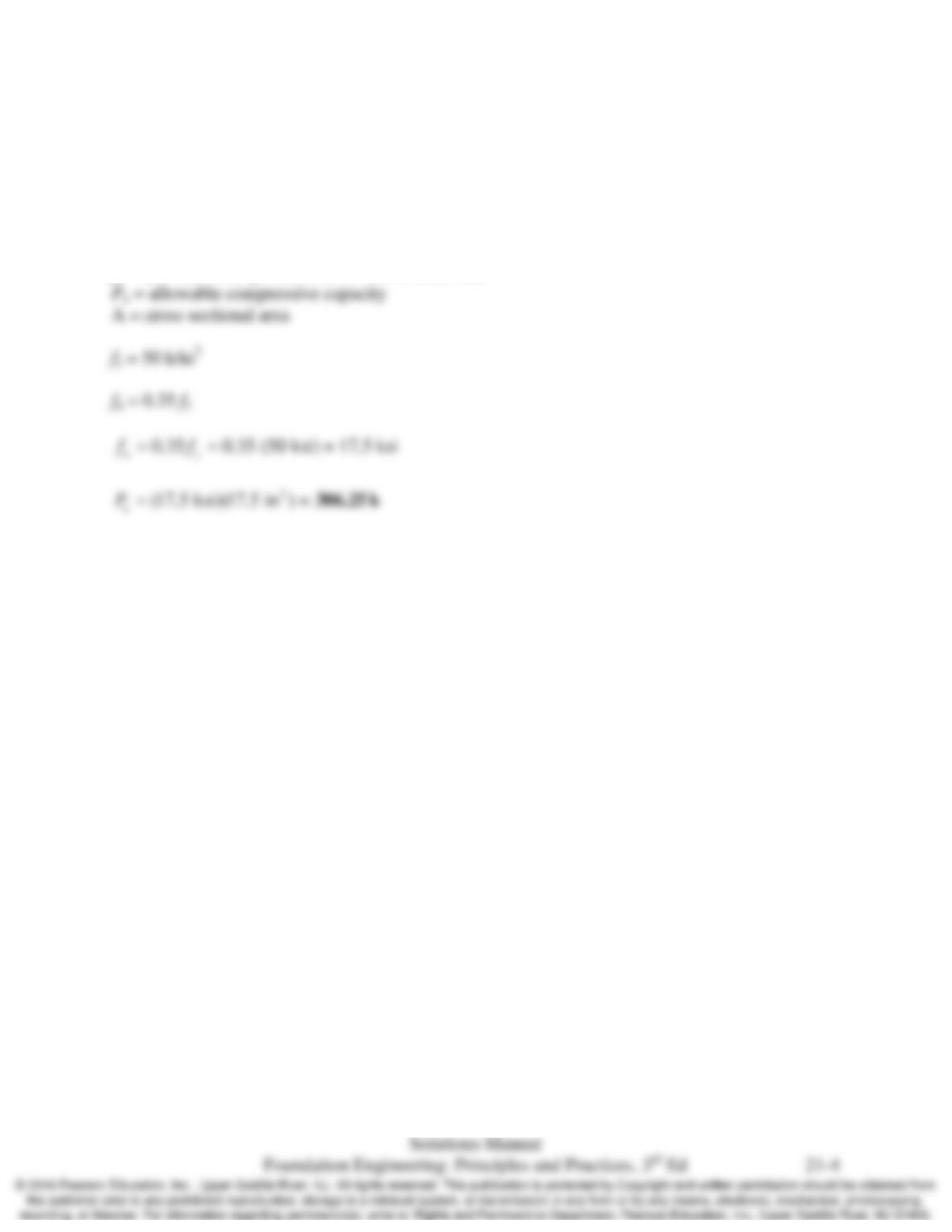
21.4 An HP 13×60 pile is made of steel with fy = 50 k/in2 and is to be loaded in compression only (i.e.,
no moment or shear loads). Using fa = 0.35 fy, compute the maximum allowable compressive
load on this pile.
Solution
fa = allowable compressive stress due to axial load
Chap. 21 Piles: Structural Design
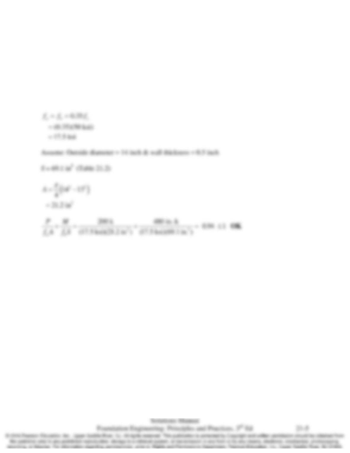
21.5 A pipe pile made of A572 steel (fy = 50 k/in2) must sustain a compressive load of 200 k and a
moment load of 40 ft–k. Using fa = 0.35 fy, select an appropriate pile size from the standard piles
listed in Table 21.2.
Solution
fy = 50 k/in2
Chap. 21 Piles: Structural Design
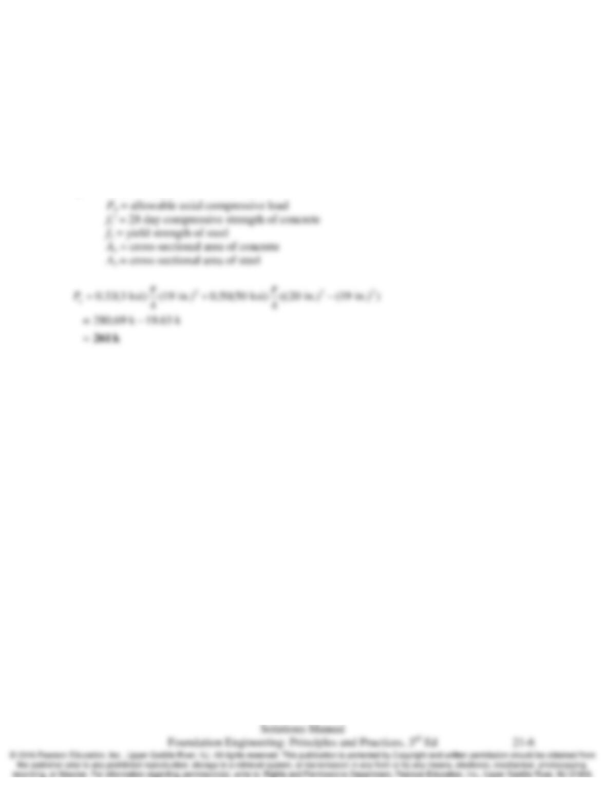
21.6 A PP20x0.500 pile made of A572 steel (fy = 50 k/in2) is to be filled with concrete having a
28-day compressive strength of 3000 lb/in2. This pile is to be loaded in compression only (i.e.,
no moment or shear loads). Using the IBC formula, compute the maximum allowable
compressive load.
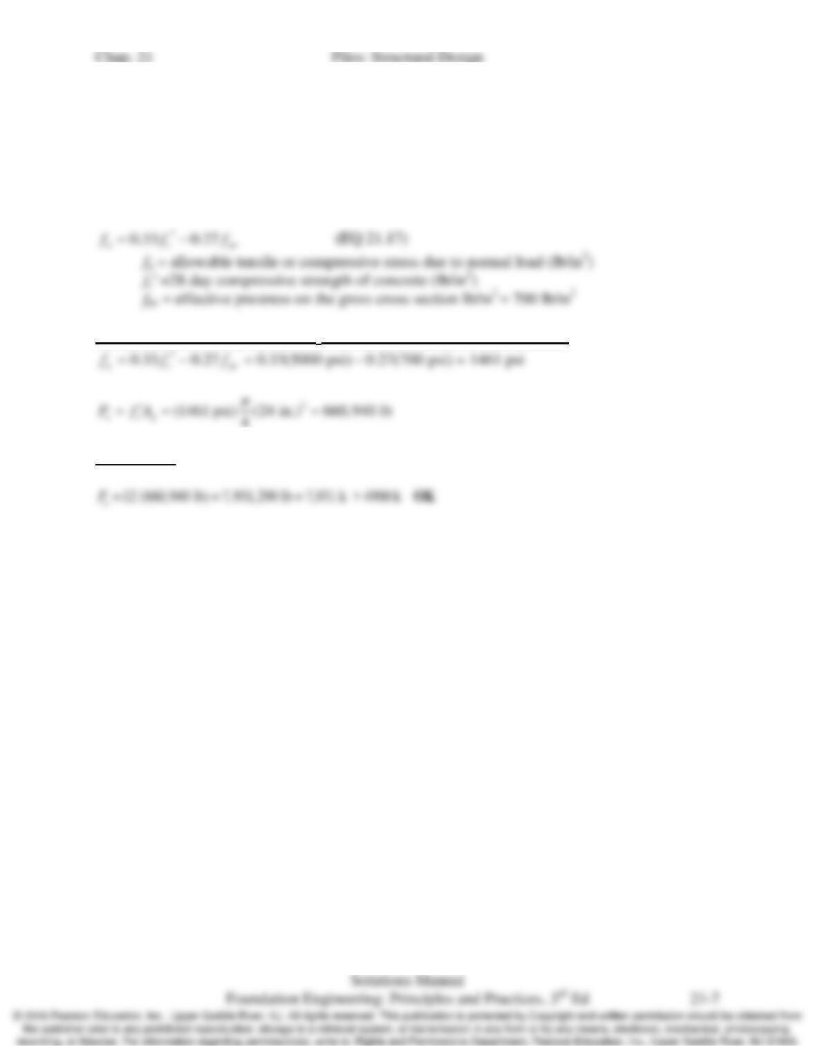
Solution
0.33 0.50
a cc ys
P fA fA
′
= +
(EQ 21.13)
21.7 A group of twelve prestressed concrete piles is to support a building column. The total
downward design load on the group is 4900 k. Assuming this load is evenly distributed across
the 12 piles, and that there are no moment or shear loads, select a pile size and 28–day
compressive strength of the concrete.
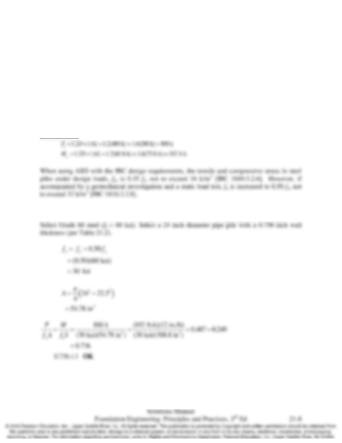
Solution
For a single pile assume 28 day fcʹ = 5000 psi and diameter = 24 inch :
For 12 piles:
Chap. 21 Piles: Structural Design
21.8 Using the standard sections in Table 21.2, select a steel pipe pile that can sustain the following
design loads:
compressive dead load = 400 k
compressive live load = 200 k
flexural dead load = 60 ft-k
flexural live load = 75 ft-k
Use the IBC load combinations, and identify the necessary steel grade and any other associated
design or construction requirements.
Solution
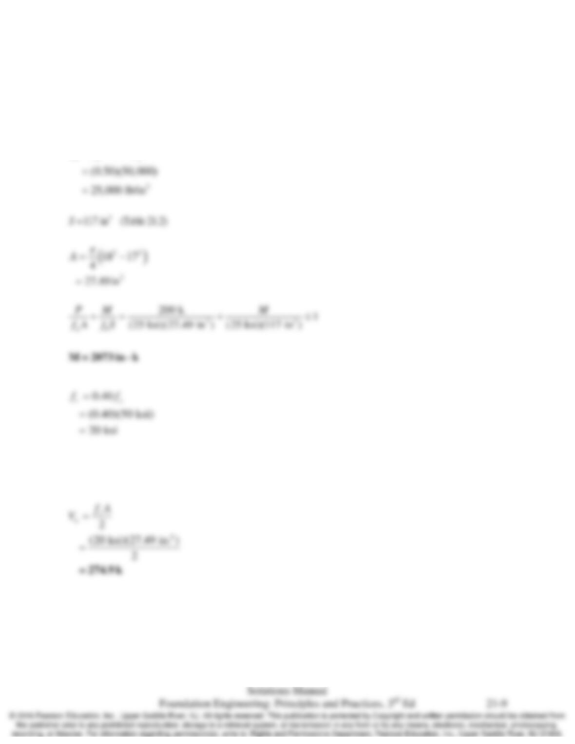
Per 2012 IBC:
Engineering recommendation: specify that a geotechnical investigation and static load test are
required as part of the subsurface investigation in order to utilize a higher fa value of 0.5 fy.
Chap. 21 Piles: Structural Design
21.9 A PP 18×0.500 steel pipe pile made of A572 steel (fy = 50 k/in2) carries a compressive load of
200 k. Compute the maximum allowable moment and shear forces that keep the pile stresses
within acceptable limits.
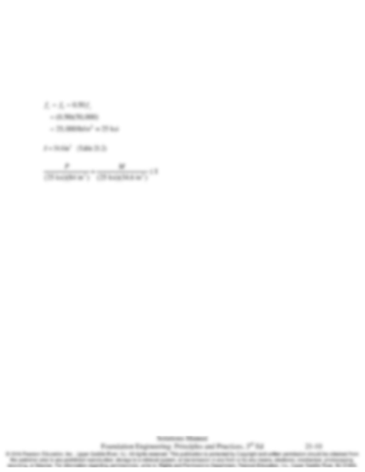
Solution
0.50
ab y
ff f= =
Due to the orientation of the steel with the direction of loading, do not use the entire cross–
sectional area for shear resistance. For H–piles, use only the area of the web; for pipe piles, use
half of the total cross-sectional area.
Chap. 21 Piles: Structural Design
21.10 Develop an interaction diagram (a plot of allowable moment load vs. allowable compressive load)
for an HP 1284 pile made of A572 steel (fy = 50 k/in2). Assume bending occurs along the weak
axis.
Solution
Develop the interaction diagram
Chap. 21 Piles: Structural Design
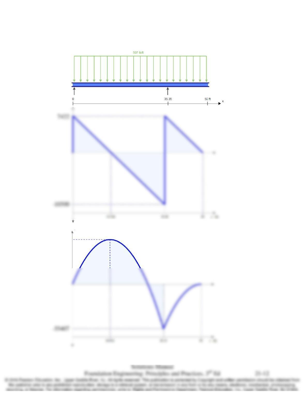
21.11 An 18-inch square, 50–ft long prestressed concrete pile with fcʹ = 6000 lb/in2 is to be lifted at a
single point as shown in Figures 21.1 and 21.2a. Using the weight of the pile plus a 50 percent
increase for inertial and impact effects, draw shear and moment diagrams for this pile. Then
compute the resulting flexural stresses and determine if this pickup arrangement satisfies the PCI
allowable stress criteria. If it does not, then suggest another method of pickup that is acceptable.
Solution
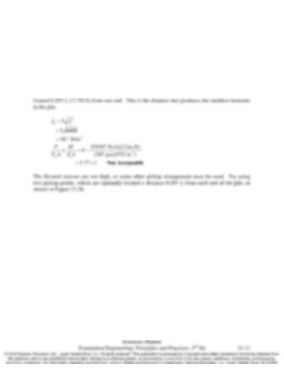
Per Table 21.4, the weight of this pile is 338 lb/ft. Multiplying by 1.5 (as recommended by PCI)
gives 507 lb/ft. The pile is to be hoisted to the pile driver by picking it up at a single point
Chap. 21 Piles: Structural Design
Shear and moment diagrams
FBD
54327.5
Chap. 21 Piles: Structural Design
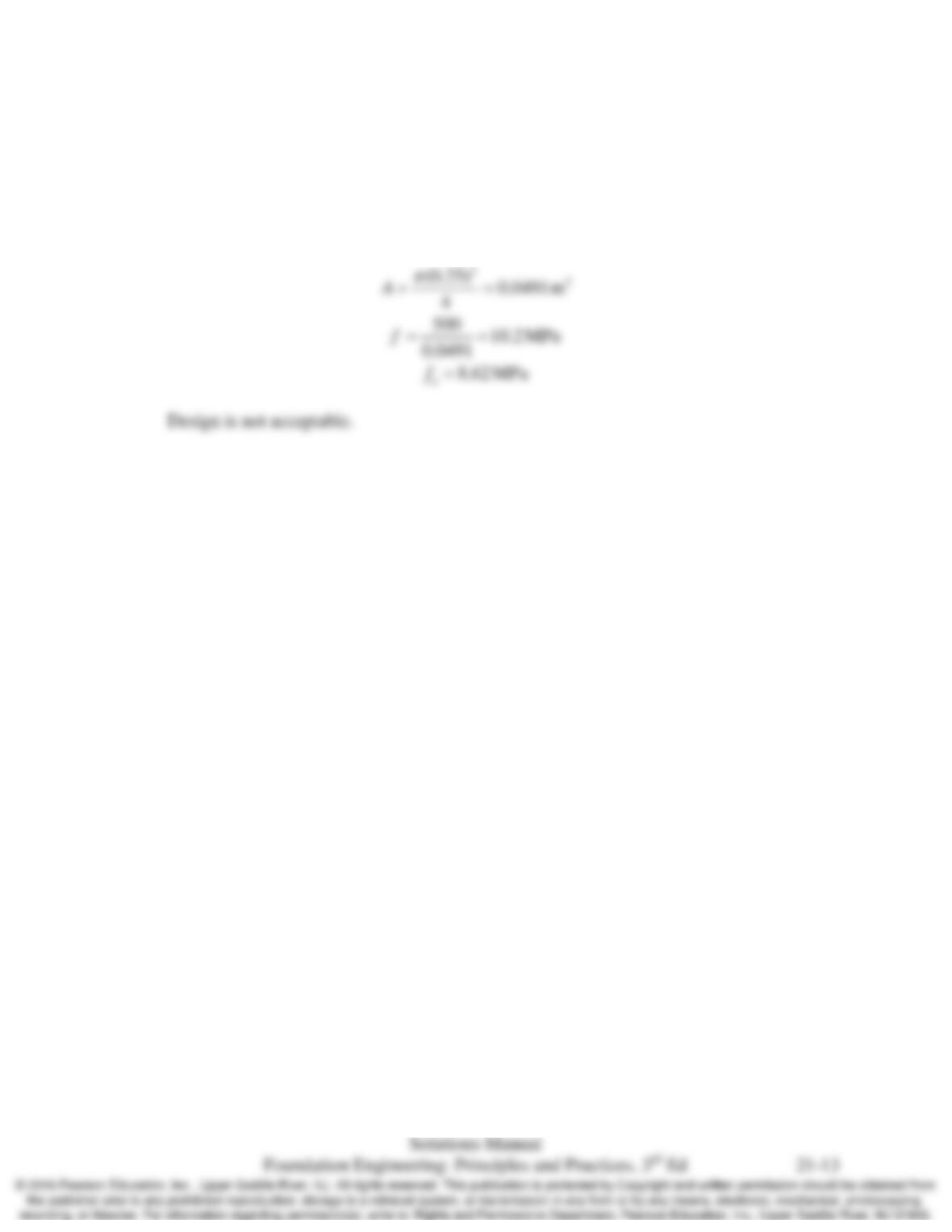
21.12 A 15 m long Douglas fir timber pile with a head diameter of 250 mm will be subjected to a
compressive load of 500 kN. There are no shear or moment loads. Is this design satisfactory from
a structural engineering perspective?
Solution