Unit 20 Design Solutions
Solutions to Unit 20 Lab Design Problems
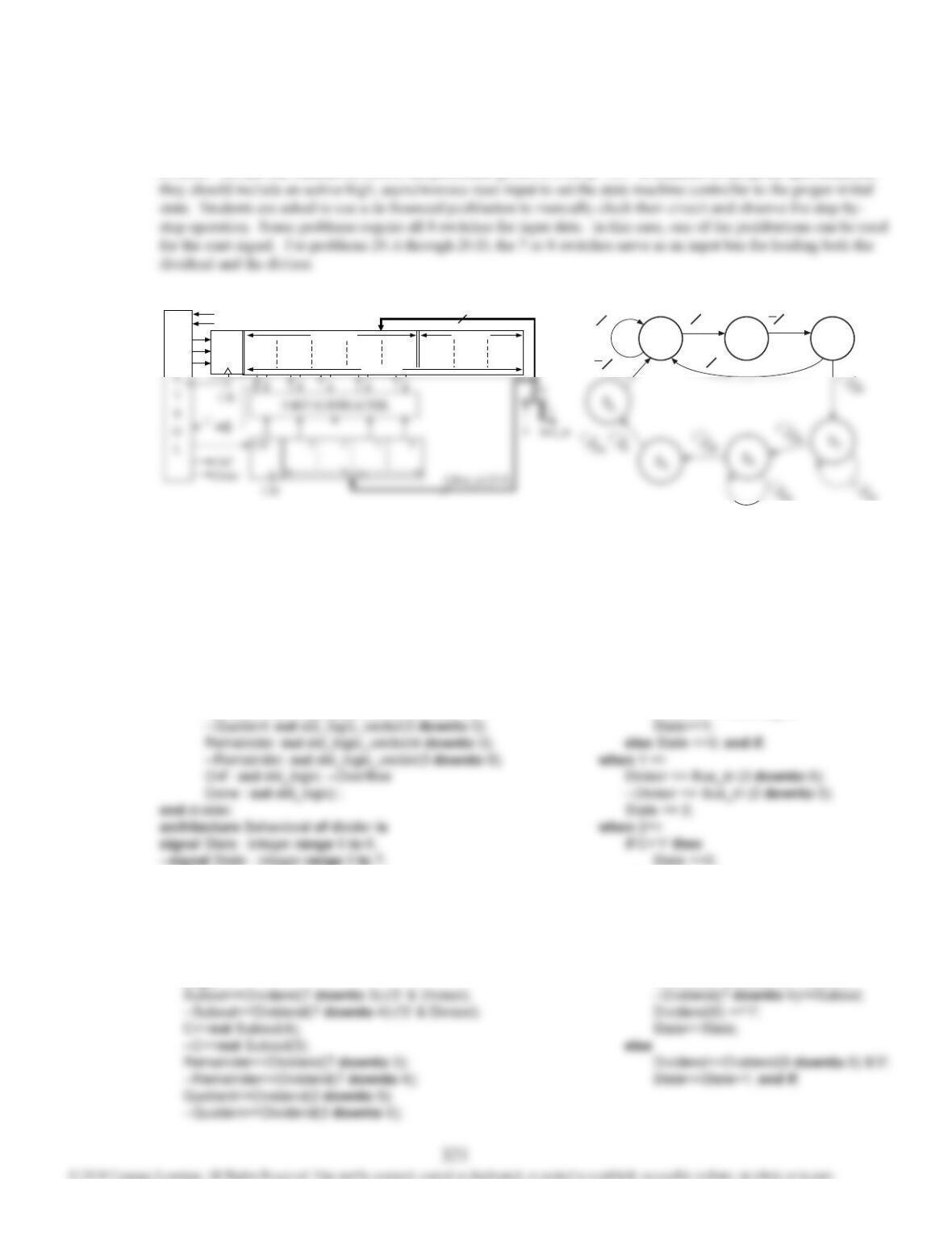
As a final lab assignment in our course, we ask students to solve one of the problems 20.A through 20.W. Each of
these problems is designed to fit on a small CPLD or FPGA circuit board with 8 input switches, 4 pushbuttons, and
8 LEDs. We ask our students to follow the procedure given on FLD p. 709. In addition to the given specifications,
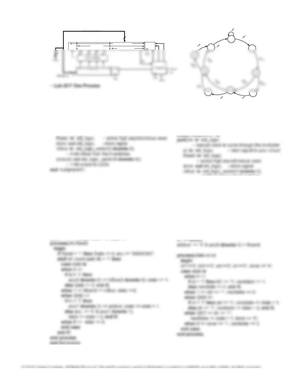
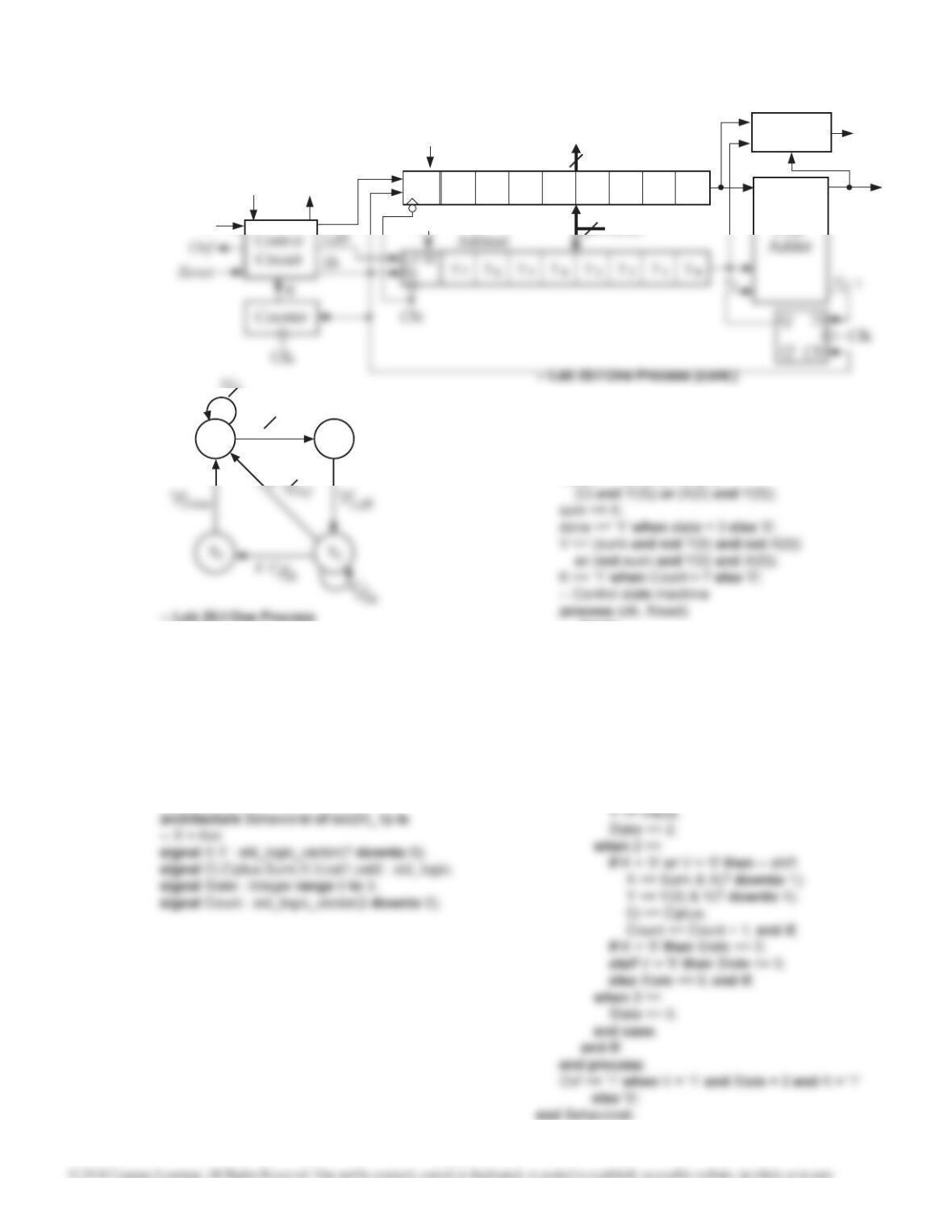
— Lab 20.A One Process
library IEEE;
use IEEE.STD_LOGIC_1164.ALL;
use IEEE.STD_LOGIC_ARITH.ALL;
use IEEE.STD_LOGIC_UNSIGNED.ALL;
entity divider is
port ( Bus_in: in std_logic_vector(6 downto 0);
St, Clk, Reset: in std_logic;
Quotient: out std_logic_vector(2 downto 0);
signal C : std_logic;
signal Subout :std_logic_vector(4 downto 0);
–signal Subout :std_logic_vector(3 downto 0);
signal Dividend: std_logic_vector(7 downto 0);
signal Divisor: std_logic_vector(3 downto 0);
–signal Divisor: std_logic_vector(2 downto 0);
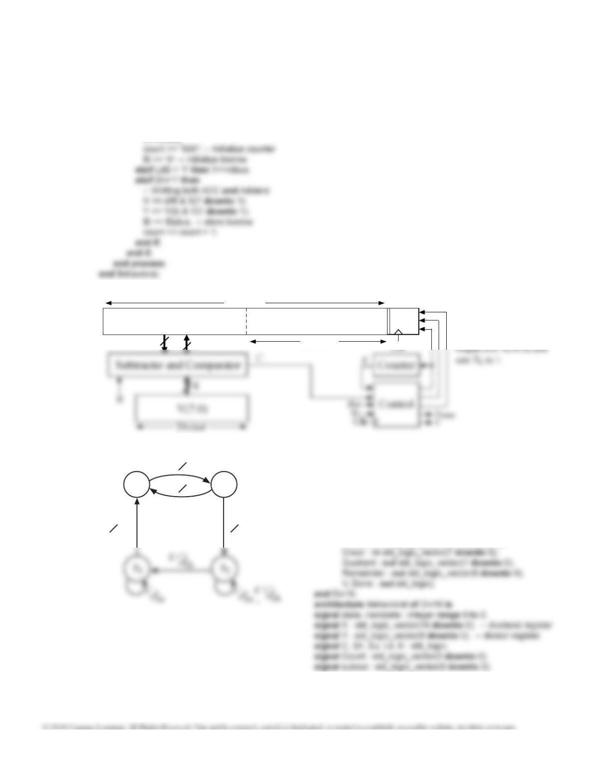
begin
3456 0127
C
O
St
Remainder Quotient
Ld1
Su
Sh
8
Dividend
Reset
— Lab 20.A One Process (cont.)
process(CLK, Reset)
begin
if Reset = ‘1’ then State <= 0;
elsif CLK’event and CLK=’1′ then
case State is
when 0 =>
if St =’1′ then
Dividend<=’0’& Bus_in;
else
Dividend <= Dividend(6 downto 0) &’0′;
State<=3; end if;
when 3|4 =>
–when 3|4|5 =>
if C=’1′ then
Dividend(7 downto 3)<=Subout;
S S S
St‘0
St Ld1
COvf
Ld2
0
1 2
Done
Note: commented code is for 20.B
20.A
Unit 20 Design Solutions
20.A
(cont.)
— Lab 20.A Two Processes
library IEEE;
use IEEE.STD_LOGIC_1164.ALL;
use IEEE.STD_LOGIC_ARITH.ALL;
use IEEE.STD_LOGIC_UNSIGNED.ALL;
entity divider is
port (Bus_in : in std_logic_vector (6 downto 0);
St, Clk, Reset : in std_logic;
architecture Behavioral of divider is
signal State, NextState : integer range 0 to 6;
–signal State, NextState : integer range 0 to 7;
signal C,Ld1, Ld2, Su, Sh : std_logic;
signal Subout :std_logic_vector(4 downto 0);
—signal Subout :std_logic_vector(3 downto 0);
— Lab 20.A Two Processes (cont.)
process(State,St,C)
begin
Ld1 <=’0′; Ld2 <= ‘0’; Sh <=’0′; Su <=’0′;
Sh <=’1′;
NextState<=3; end if;
when 3|4 =>
–when 3|4|5 =>
if C=’1′ then
Su <=’1′;
NextState<=State;
else
Sh <=’1′;
NextState <=6;
–NextState <= 7;
when 6 =>
—when 7 =>
NextState <= 0;
Done <= ‘1’;
end case;
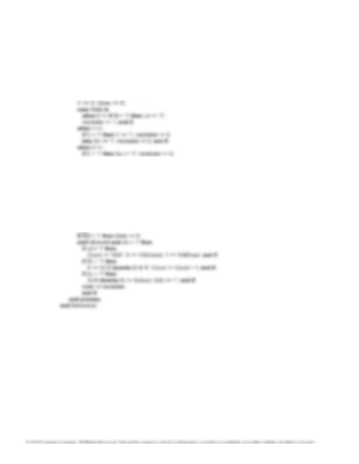
— Lab 20.A One Process (cont.)
when 5=>
–when 6=>
if C=’1′ then
323
Unit 20 Design Solutions
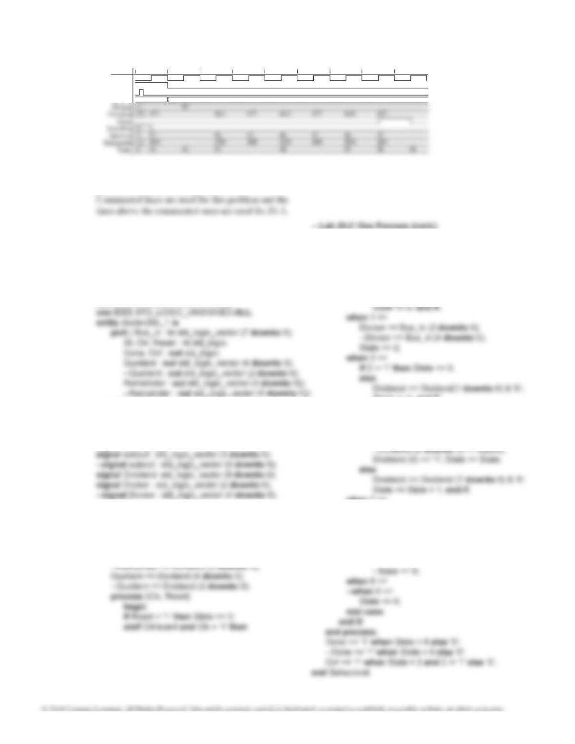
0ns 200ns 400ns 600ns 800ns 1000ns 1200ns 1400ns 1600ns
Clk
St
Reset
Bus_in
Signal
77 0F
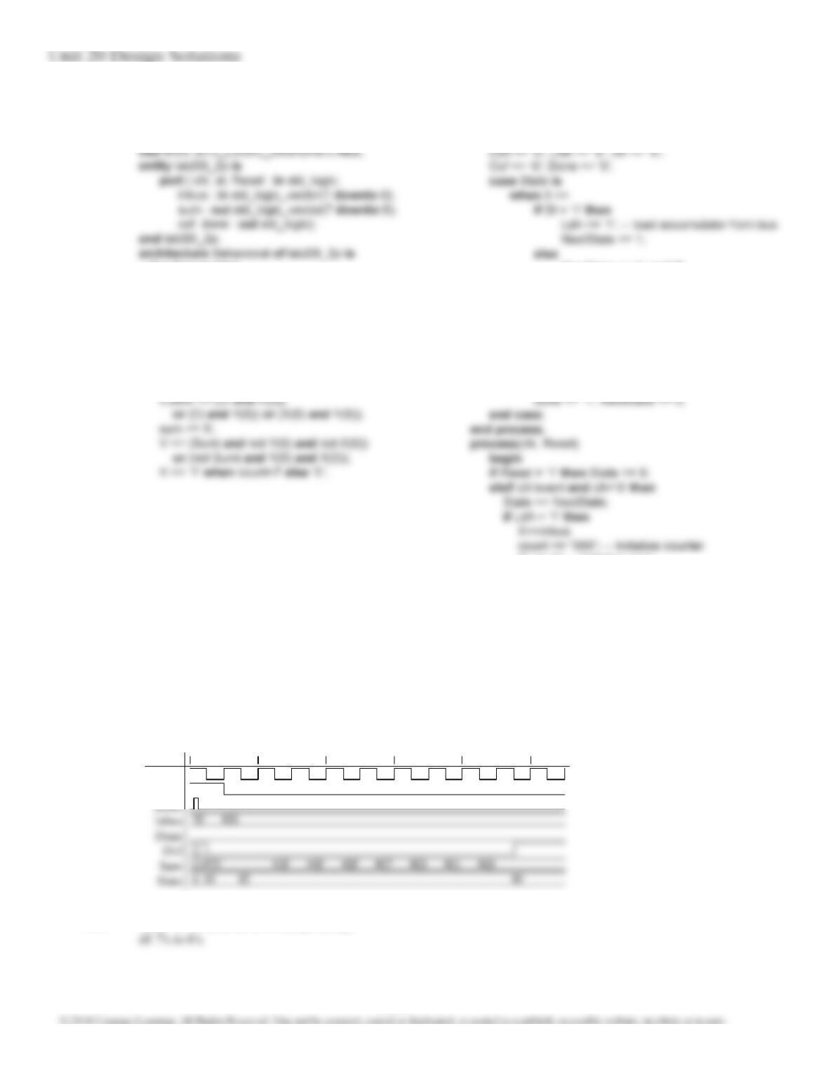
Waveform for 1110111 / 1111 = 111 remainder 01110:
20.A
(cont.)
20.B For the corresponding code for the one and two
process solutions, refer to problem 20.A.
20.C
— Lab 20.C One Process
library IEEE;
use IEEE.STD_LOGIC_1164.ALL;
use IEEE.STD_LOGIC_ARITH.ALL;
end divider20c_1;
architecture Behavioral of divider20c_1 is
signal State : integer range 0 to 8;
–signal State : integer range 0 to 6;
signal C : std_logic;
begin
subout <= Dividend(8 downto 5) – (‘0’&Divisor);
–subout <= Dividend(8 downto 3) – (‘0’&Divisor);
C <= not subout (3);
–C <= not subout (5);
Remainder <= Dividend (8 downto 5);
Note: commented code is for 20.D
case State is
when 0 =>
if St = ‘1’ then
Dividend <= ‘0’ & Bus_in;
State <= 1;
else
State <= 3; end if;
when 3|4|5|6 =>
–when 3|4 =>
if C = ‘1’ then
Dividend (8 downto 5) <= subout;
when 7 =>
–when 5 =>
if C = ‘1’ then
Dividend (8 downto 5) <= subout;
–Dividend (8 downto 3) <= subout;
Dividend (0) <= ‘1’; end if;
State <= 8;
324
Unit 20 Design Solutions
— Lab 20.C Two Processes
library IEEE;
use IEEE.STD_LOGIC_1164.ALL;
use IEEE.STD_LOGIC_ARITH.ALL;
use IEEE.STD_LOGIC_UNSIGNED.ALL;
entity divider20c_1 is
port (Bus_in : in std_logic_vector (7 downto 0);
end divider20c_1;
architecture Behavioral of divider20c_1 is
signal State, NextState : integer range 0 to 8;
—signal State, NextState : integer range 0 to 6;
signal C, Sh, Su, Ld1, Ld2 : std_logic;
signal subout : std_logic_vector (3 downto 0);
—signal subout : std_logic_vector (5 downto 0);
signal Dividend: std_logic_vector (8 downto 0);
signal Divisor : std_logic_vector (2 downto 0);
20.C
(cont.)
— Lab 20.C Two Processes (cont.)
case State is
when 0 =>
if St = ‘1’ then Ld1 <= ‘1’; NextState <= 1;
else NextState <= 0; end if;
when 1 =>
Ld2 <= ‘1’; NextState <= 2;
when 2 =>
when 7 =>
—when 5 =>
if C = ‘1’ then Su<= ‘1’; end if;
NextState <= 8;
–NextState <= 6;
when 8 =>
—when 6 =>
Done <= ‘1’; NextState <= 0;
end case;
end if;
end process;
end Behavioral;
20.D For the corresponding code for the one and two
process solutions, refer to problem 20.C.
Commented lines are used for this problem and the
lines above the commented ones are used for 20.C.
4
inBus[3:0]
S1
S0
St’0
St Ld1
–Ld2
–done
M’
– Sh
S10
S9
20.E
325
Unit 20 Design Solutions
20.E
(cont.)
— Lab 20 E One Process
library IEEE;
use IEEE.STD_LOGIC_1164.ALL;
use IEEE.STD_LOGIC_ARITH.ALL;
use IEEE.STD_LOGIC_UNSIGNED.ALL;
entity multiplier347 is
port(clk: in std_logic;
— manual clock to cycle through the multiplier
architecture Behavioral of multiplier347 is
signal state, nextstate: integer range 0 to 10;
signal acc: std_logic_vector(7 downto 0);
signal Mcand: std_logic_vector(2 downto 0);
signal m: std_logic;
signal addout: std_logic_vector(3 downto 0);
begin
product <= acc(6 downto 0);
when 3|5|7|9 => acc <= ‘0’ & acc(7 downto 1);
state <= state + 1;
when 10 => state <= 0;
end case;
end if;
end process;
end Behavioral;
— Lab 20 E Two Processes
library IEEE;
use IEEE.STD_LOGIC_1164.ALL;
use IEEE.STD_LOGIC_ARITH.ALL;
use IEEE.STD_LOGIC_UNSIGNED.ALL;
entity multiplier347 is
port(clk: in std_logic;
— manual clock to cycle through the multiplier
st: in std_logic;
signal acc : std_logic_vector(7 downto 0);
signal Mcand: std_logic_vector(2 downto 0);
signal m : std_logic;
signal addout : std_logic_vector(3 downto 0);
signal ld1,ld2, ad, sh : std_logic;
begin
product <= acc(6 downto 0);
m <= acc(0);
process(clk, Reset)
begin
if Reset = ‘1’ then State <= 0; acc <= “00000000”;
elsif clk’ event and clk = ‘1’ then
if ld1 = ‘1’ then
acc(3 downto 0) <= inBus; end if;
if ld2 = ‘1’ then
Mcand <= inBus(2 downto 0); end if;
326
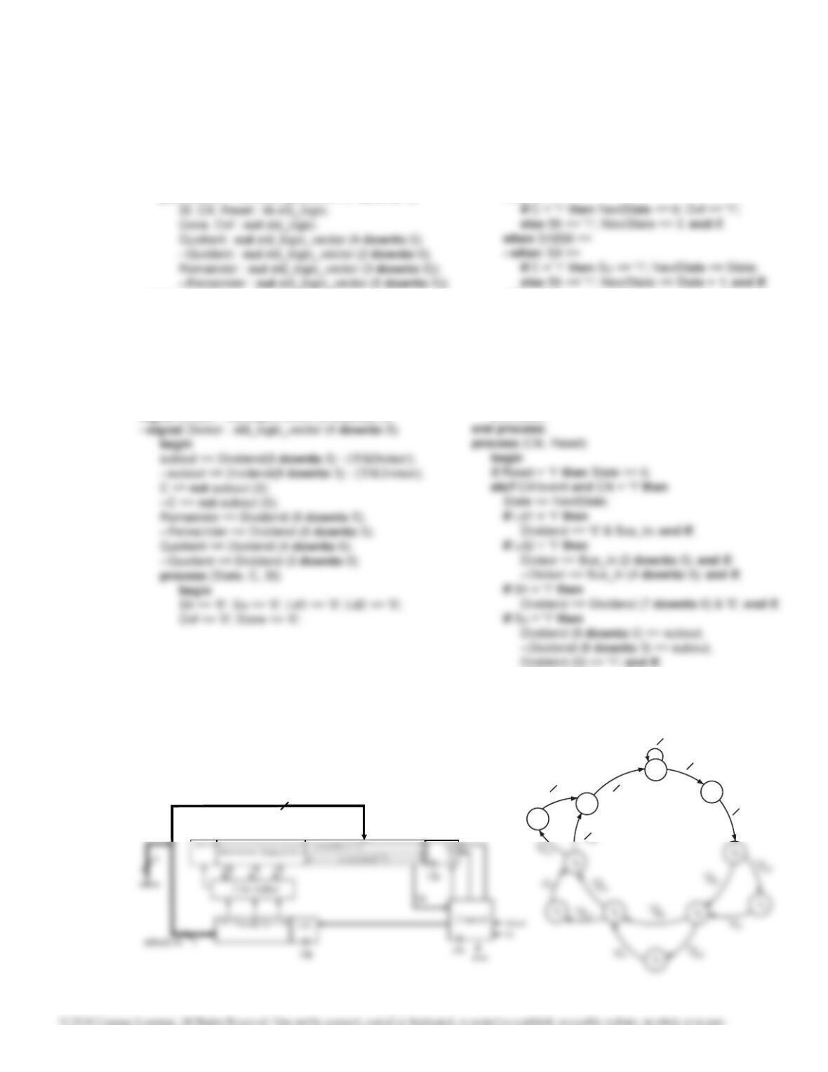
Unit 20 Design Solutions
20.F
Accumulator[7:0]
Accumulator[2:0]
Ld1
3
Sh
Ad
Product[6:0]
inBus[2:0]
S1
S0
St’0
St Ld1
–done
MAd
– Sh
S8
– Sh
S5
library IEEE;
use IEEE.STD_LOGIC_1164.ALL;
use IEEE.STD_LOGIC_ARITH.ALL;
use IEEE.STD_LOGIC_UNSIGNED.ALL;
entity multiplier437 is
port(clk: in std_logic;
— manual clock to cycle through the multiplier
st: in std_logic; — start signal to your circuit
architecture Behavioral of multiplier437 is
signal state, nextstate: integer range 0 to 8;
signal acc: std_logic_vector(7 downto 0);
signal Mcand: std_logic_vector(3 downto 0);
signal m: std_logic;
signal addout: std_logic_vector(4 downto 0);
begin
product <= acc(6 downto 0);
m <= acc(0);
addout <= ‘0’ & acc(6 downto 3) + Mcand;
done <= ‘1’ when state = 8 else ‘0’;
— Lab 20 F Two Processes
library IEEE;
use IEEE.STD_LOGIC_1164.ALL;
use IEEE.STD_LOGIC_ARITH.ALL;
use IEEE.STD_LOGIC_UNSIGNED.ALL;
— 4-bit input from the 8 switches
product: out std_logic_vector(6 downto 0));
end multiplier437;
architecture Behavioral of multiplier437 is
signal state, nextstate: integer range 0 to 8;
signal acc: std_logic_vector(7 downto 0);
signal Mcand: std_logic_vector(3 downto 0);
signal m: std_logic;
signal addout: std_logic_vector(4 downto 0);
signal ld1,ld2, ad, sh : std_logic;
begin
product <= acc(6 downto 0);
327
Unit 20 Design Solutions
20.F
(cont.)
— Lab 20 F Two Processes (cont.)
process(clk, Reset)
begin
if Reset = ‘1’ then State <= 0; acc <= “00000000”;
elsif clk’ event and clk = ‘1’ then
Accumulator[8:0]
Accumulator[2:0]
Ld1
3
Sh
Ad
Product[7:0]
inBus[2:0]
20.G
–Ld2
M’
Sh
20G
M’
Sh
M’
Sh
MAd
MAd
MAd
– Sh
S2
S5
S6
S4S3
– Sh
— Lab 20.G One Process
library IEEE;
use IEEE.STD_LOGIC_1164.ALL;
use IEEE.STD_LOGIC_ARITH.ALL;
use IEEE.STD_LOGIC_UNSIGNED.ALL;
— 8-bit output to LEDs
end multiplier538;
architecture Behavioral of multiplier538 is
signal state, nextstate: integer range 0 to 8;
— Lab 20.G One Process (cont.)
process (clk, Reset)
begin
if Reset = ‘1’ then State <= 0; acc <= “000000000”;
elsif clk’event and clk =’1’ then
state <=state + 2; end if;
when 3|5|7 =>
acc <=’0’ &acc(8 downto 1); state <= state + 1;
when 8 => state <= 0;
end case;
20.G
(cont.)
Unit 20 Design Solutions
— Lab 20G Two Processes
library IEEE;
use IEEE.STD_LOGIC_1164.ALL;
use IEEE.STD_LOGIC_ARITH.ALL;
use IEEE.STD_LOGIC_UNSIGNED.ALL;
architecture Behavioral of multiplier538 is
signal state, nextstate: integer range 0 to 8;
signal acc: std_logic_vector(8 downto 0);
signal Mcand: std_logic_vector(4 downto 0);
signal m: std_logic;
20.G
(cont.)
Accumulator[8:0]
Ld1
5
Sh
Product[7:0]
inBus[4:0]
S1
S0
S5
St’0
St Ld1
–done
MAd
– Sh
– Sh
S7
library IEEE;
use IEEE.STD_LOGIC_1164.ALL;
use IEEE.STD_LOGIC_ARITH.ALL;
use IEEE.STD_LOGIC_UNSIGNED.ALL;
entity multiplier358 is
port(clk: in std_logic; — manual clock to cycle through the multiplier
st: in std_logic; — start signal to your circuit
Reset: in std_logic; — active high asynchronous reset
— Lab 20G Two Processes (cont.)
process (state, st, m)
begin
ld1 <= ‘0’ ; ld2 <= ‘0’ ; ad <= ‘0’ ; sh <= ‘0’ ; done <= ‘0’;
case state is
end process;
process (clk, Reset)
begin
if Reset =’1’ then State <= 0; acc <= “000000000”;
elsif clk’event and clk = ‘1’ then
20.H
20.H
(cont.)
— Lab 20 H One Process (cont.)
begin
product <=acc(7 downto 0);
m <= acc(0);
addout <= ‘0’ & acc(7 downto 5) + Mcand;
done <= ‘1’ when state = 12 else ‘0’;
process (clk , Reset)
— Lab 20.H Two Processes
library IEEE;
use IEEE.STD_LOGIC_1164.ALL;
use IEEE.STD_LOGIC_ARITH.ALL;
use IEEE.STD_LOGIC_UNSIGNED.ALL;
entity multiplier358 is
port(clk: in std_logic;
— manual clock to cycle through the multiplier
st: in std_logic; — start signal to your circuit
Reset: in std_logic; — active high asynchronous reset
done: out std_logic; –done signal
20.H
(cont.)
— Lab 20.H Two Processes (cont.)
process (state, st, m)
begin
ld1 <= ‘0’ ; ld2 <= ‘0’ ; ad <= ‘0’ ; sh <= ‘0’; done <= ‘0’;
case state is
when 0 =>
if st =’1’ then ld1 <= ‘1’ ; nextstate <= 1;
else nextstate <= 0; end if;
when 1 => ld2<= ‘1’ ; nextstate <= 2 ;
when 2|4|6|8|10 =>
if m =’1’ then ad <= ‘1’ ; nextstate <= state + 1;
330
Unit 20 Design Solutions
20.I
sum
Full
i
x3x2x1x0
x7x6x5x4
Accumulator
Ld
Sh
Overflow
Logic V
LdA
8inbus
8
Sum
Done
sumi
y(0)
St
SI
V
S0S1
St LdA
St’0
S1
S0
library IEEE;
use IEEE.STD_LOGIC_1164.ALL;
use IEEE.STD_LOGIC_ARITH.ALL;
use IEEE.STD_LOGIC_UNSIGNED.ALL;
entity lab20I_1p is
port ( clk, st, Reset : in std_logic;
inbus : in std_logic_vector(7 downto 0);
sum : out std_logic_vector(7 downto 0);
done, ovf : out std_logic);
end lab20I_1p;
begin
cat1 <= ‘0’; — Needed to use the 7 segment display
cat2 <= ‘1’; — to provide a 9th LED
Sumi <= X(0) xor Y(0) xor Ci; — 1-bit adder
Ciplus <= (Ci and X(0)) or
begin
if Reset = ‘1’ then State <= 0;
elsif clk’event and clk=’0′ then
case State is
when 0 =>
if St = ‘1’ then
X <= inbus; — load accumulator from bus
Ci <=’0′; — Clear the carry bit
Count <= “000”;
State <= 1; end if;
when 1 =>
331
— Lab 20.I Two Processes (cont.)
— Control state machine
process (State,St,K,V)
begin
NextState <= 0; end if;
when 1 =>
LdB <= ‘1’; NextState <= 2;
when 2 =>
if K = ‘0’ then Sh <= ‘1’; else
if V = ‘0’ then Sh <= ‘1’; NextState <= 3;
else ovf <= ‘1’; NextState <= 0; end if;
end if;
when 3 =>
Ci <= ‘0’; — Initialize carry
elsif LdB = ‘1’ then Y<=inbus;
elsif Sh=’1’ then
— Shifting both ACC and Addend
X <= Sumi & X(7 downto 1);
Y <= Y(0) & Y(7 downto 1);
Ci <= Ciplus; — store carry
count <= count + 1; end if;
end if;
end process;
end Behavioral;
— Lab 20.I Two Processes
Library IEEE;
use IEEE.STD_LOGIC_1164.ALL;
use IEEE.STD_LOGIC_ARITH.ALL;
— X = Accumulator
signal X,Y : std_logic_vector(7 downto 0);
signal Sh,Ci,Ciplus,Sumi,K,LdA,LdB,V,cat1,cat2 : std_logic;
signal State, NextState : integer range 0 to 3;
signal count : std_logic_vector(2 downto 0);
begin
cat1 <= ‘0’; — Needed to use the 7 segment display
cat2 <= ‘1’; — To provide a 9th LED
Sumi <= X(0) xor Y(0) xor Ci; — 1-bit adder
20.I
(cont.)
20.J Same as solution for 20.I except change
0ns 400ns 800ns 1200ns 1600ns 2000ns
Clk
St
Signal
Waveform for 01111111 + 00000001 = 10000000 (overow):
332
Unit 20 Design Solutions
20.K — Lab 20.K One Process
library IEEE;
use IEEE.STD_LOGIC_1164.ALL;
use IEEE.STD_LOGIC_ARITH.ALL;
use IEEE.STD_LOGIC_UNSIGNED.ALL;
entity lab20K_1p is
signal Bi,Biplus,diffi,K,V,cat1,cat2 : std_logic;
signal State : integer range 0 to 3;
signal Count : std_logic_vector(2 downto 0);
begin
cat1 <= ‘0’; — Needed to use the 7 segment display
process (clk, Reset)
begin
if Reset = ‘1’ then State <= 0;
elsif clk’event and clk=’0’ then
case State is
when 0 =>
if St = ‘1’ then
X <= inbus; — load accumulator from bus
when 3 =>
State <= 0;
end case;
end if;
— Lab 20.K Two Processes
library IEEE;
use IEEE.STD_LOGIC_1164.ALL;
use IEEE.STD_LOGIC_ARITH.ALL;
use IEEE.STD_LOGIC_UNSIGNED.ALL;
entity lab20K_2p is
— X = Accumulator
signal Sh,Bi,Biplus,diffi,K,LdA,LdB,V : std_logic;
signal State, NextState : integer range 0 to 3;
signal count : std_logic_vector(2 downto 0);
signal cat1, cat2 : std_logic;
begin
begin
LdA <= ‘0’; LdB <= ‘0’; Sh <= ‘0’;
Ovf <= ‘0’; Done <= ‘0’;
case State is
when 0 =>
if St = ‘1’ then
LdA <= ‘1’; — load accumulator from bus
NextState <= 1;
end process;
333
Unit 20 Design Solutions
20.K
(cont.)
20.L Same as solution to 20.K except change
all 7’s to 6’s.
20.M
— Lab 20.K Two Processes (cont.)
process(clk, Reset)
begin
if Reset = ‘1’ then State <= 0;
elsif clk’event and clk=’0’ then
State <= NextState;
if LdA = ‘1’ then
S0S1
St Ld
S1
S0
Sh
C’
Done
C’
CV
— Lab 20.M Two Processes
library IEEE;
use IEEE.STD_LOGIC_1164.ALL;
use IEEE.STD_LOGIC_ARITH.ALL;
use IEEE.STD_LOGIC_UNSIGNED.ALL;
entity Div16 is
port (CLK, St. Rst : in std_logic;
Dvend : in std_logic_vector(15 downto 0);
Quotient
Ld
Sh
Su
Dividend
X(16:8) X(7:0)
99
Note: Su loads subtracter
334
Unit 20 Design Solutions
— Lab 20.M Two Processes (cont.)
begin
Quotient <= X(7 downto 0);
Remainder <= X(16 downto 8);
K <= ‘1’ when Count = 7 else ‘0’;
Subout <= X(16 downto 8) – Y;
C <= not Subout(8);
process (state, St, C, K)
begin
Ld <= ‘0’; Sh <= ‘0’; Su <= ‘0’;
else
Sh <= ‘1’;
if K = ‘0’ then nextstate <= 2;
else nextstate <= 3; end if;
end if;
when 3 =>
if C = ‘1’ then Su <= ‘1’; nextstate <= 3;
else Done <= ‘1’; nextstate <= 0; end if;
end case;
end process;
process(clk, Rst)
begin
20.M
(cont.)
335
Unit 20 Design Solutions
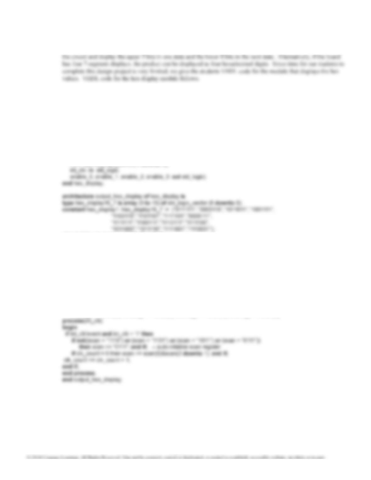
Lab Design Problems 20.N, 20,O, 20.P, and 20.Q.
These problems require the design of a multiplier with a product that is 13 bits long. If your students are using a
board that has only 8 LEDs, two strategies could be used to display the product. One way is to add an extra state to
— The following module displays a 16-bit answer as four hexadecimal digits.
— The constant array converts each 4- bit pattern to a 7-bit pattern to drive the 7-segment indicators.
— The 7-bit LCD output drives all four indicators in parallel.
— The scan signal selects each of the four 7-segment indicators in turn
— and multiplexes the four digits from the bit_data input.
library IEEE;
use IEEE.STD_LOGIC_1164.ALL;
use IEEE.STD_LOGIC_ARITH.ALL;
use IEEE.STD_LOGIC_UNSIGNED.ALL;
entity hex_display is
port(bit_data: in std_logic_vector(15 downto 0);
LCD: out std_logic_vector( 6 downto 0);
signal digit: std_logic_vector(3 downto 0);
signal index: integer range 0 to 15;
signal scan: std_logic_vector(3 downto 0);
signal clk_count: std_logic_vector(8 downto 0):= “000000000”;
begin
digit <= bit_data(3 downto 0) when scan(0) = ‘0’
else bit_data(7 downto 4) when scan(1) = ‘0’
else bit_data(11 downto 8) when scan(2) = ‘0’
else bit_data(15 downto 12) when scan(3) = ‘0’
else “0000”;
index <= conv_integer(digit);
LCD <= not hex_display1(index);
enable_0 <= scan(3); enable_1 <= scan(2); enable_2 <= scan(1); enable_3 <= scan(0);
Note: For consistency with the input to this hex-display module, we have added three
initial 0’s to the 13-bit product in each of the solutions for Problems 20.N, 20.O, 20.P and
20.Q.