Problem 2.40
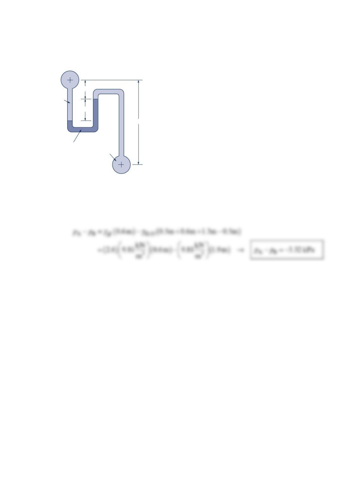
Two pipes are connected by a manometer as shown in the figure below. Determine the
pressure difference −
AB
p
p, between the pipes.
Solution 2.40
()()()
γγγ
++−+−=
2 2
AHO gf HO B
0.5m 0.6m 0.6 m 1.3m 0.5m
p
p
Gage fluid
(
SG
= 2.6)
1.3 m
0.5 m
0.6 m
Water
Water
B
A
Problem 2.41
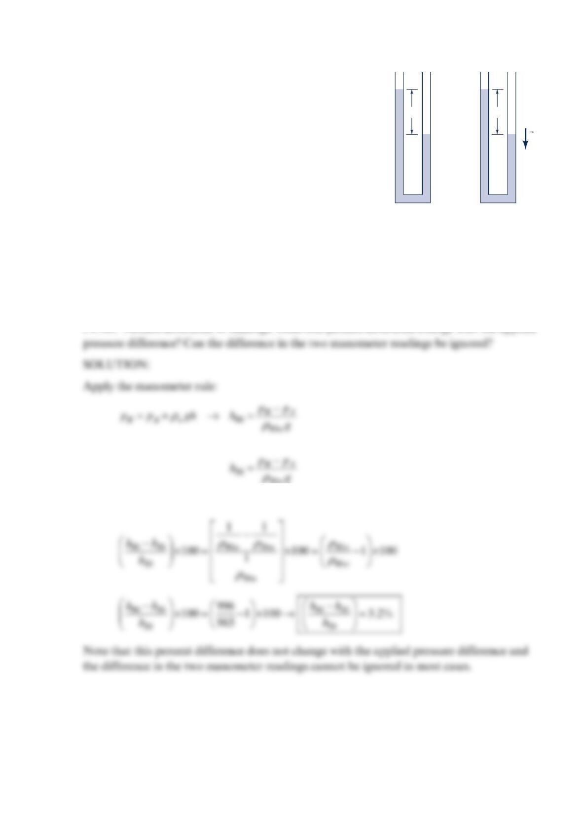
Find the percentage difference in the readings of the two
identical U-tube manometers shown in the figure below.
Manometer 90 uses °90 C water and manometer 30 uses
°30 C water. Both have the same applied pressure
difference. Does this percentage change with the magnitude
of the applied pressure difference? Can the difference
between the two readings be ignored?
Solution 2.41
GIVEN: Figure, Two identical U-tube manometers. Manometer 90 uses °90 C water
while manometer 30 uses °30 C water. Same pressure difference applied across each
manometer.
FIND: Percent difference in readings. Does this percent difference change with the applied
30
w
Using the °30 C water as a reference
Manometer 90
h90
g
Manometer 30
h30
Problem 2.42
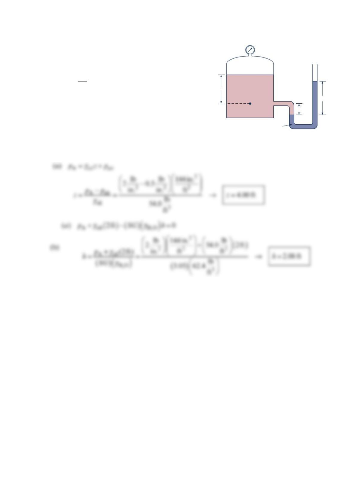
A U-tube manometer is connected to a closed tank as
shown in the figure below. The air pressure in the
tank is 0.50 psi and the liquid in the tank is oil
(
γ
=3
lb
54.0 ft ). The pressure at point A is 2.00 psi.
Determine: (a) the depth of oil, z, and (b) the
differential reading,
h
, on the manometer.
Solution 2.42
Open
Air
Oil
A
z
h
2 ft
SG = 3.05
Problem 2.43
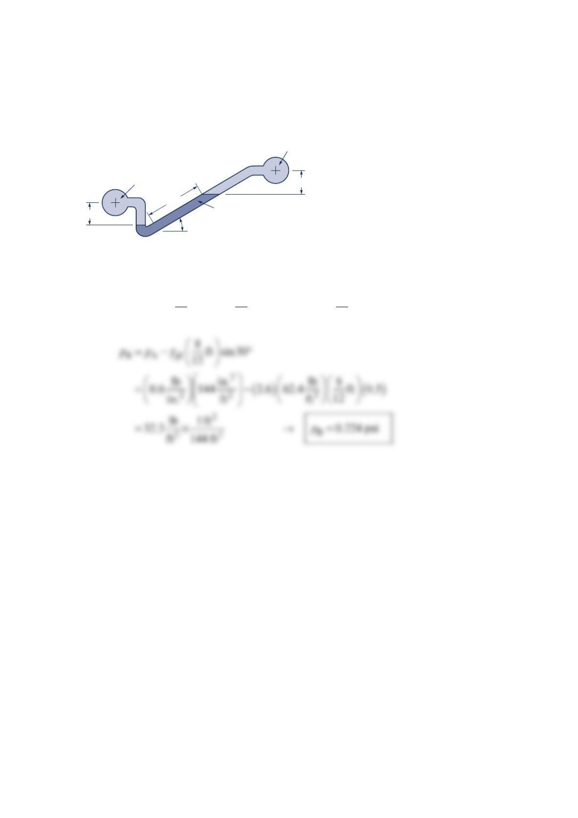
For the inclined-tube manometer of the figure below, the pressure in pipe A is 0.6 psi. The
fluid in both pipes A and B is water, and the gage fluid in the manometer has a specific
gravity of 2.6. What is the pressure in pipe B corresponding to the differential reading
shown?
Solution 2.43
γγ γ
+− °−=
2 2
AHO gf HO B
38 3
ft ft sin30 ft
12 12 12
p
p
Water
Water
8 in.
30°
3 in.
3 in.
A
B
SG
= 2.6
Problem 2.44
A flowrate measuring device is installed in a horizontal pipe through which water is
flowing. A U-tube manometer is connected to the pipe through pressure taps located 3 in.
on either side of the device. The gage fluid in the manometer has a specific weight of
3
lb
122 ft . Determine the differential reading of the manometer corresponding to a pressure
drop between the taps of 2
lb
0.5 in. .
Solution 2.44
Let 1
p
and 2
p
be pressures at pressure taps.
Flowmeter
p
p
H
h
p
L
A
p
R
ρ
A
ρ
B
ρ
Problem 2.45
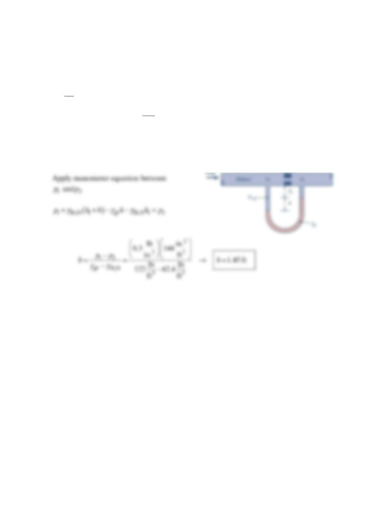
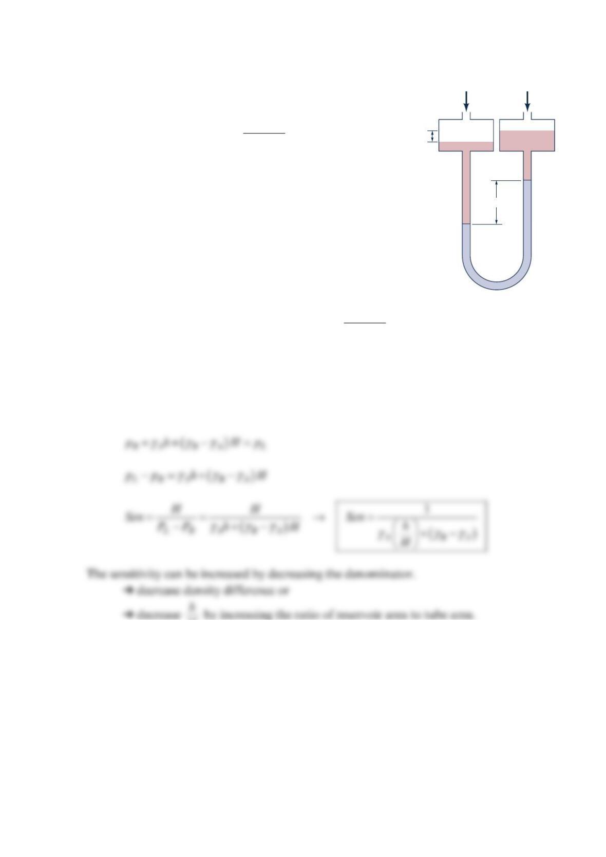
The sensitivity Sen of the micromanometer shown in the figure
below is defined as
=−
LR
H
Sen
p
p.
Find the sensitivity of the micromanometer in terms of the
densities
ρ
A and B
ρ
. How can the sensitivity be increased?
Solution 2.45
GIVEN: Figure and sensitivity defined as: =−
LR
H
Sen
p
p.
FIND: Sensitivity as a function of fluid densities. How can the sensitivity increase?
SOLUTION:
Apply manometer rule,
H by increasing the ratio of reservoir area to tube area.
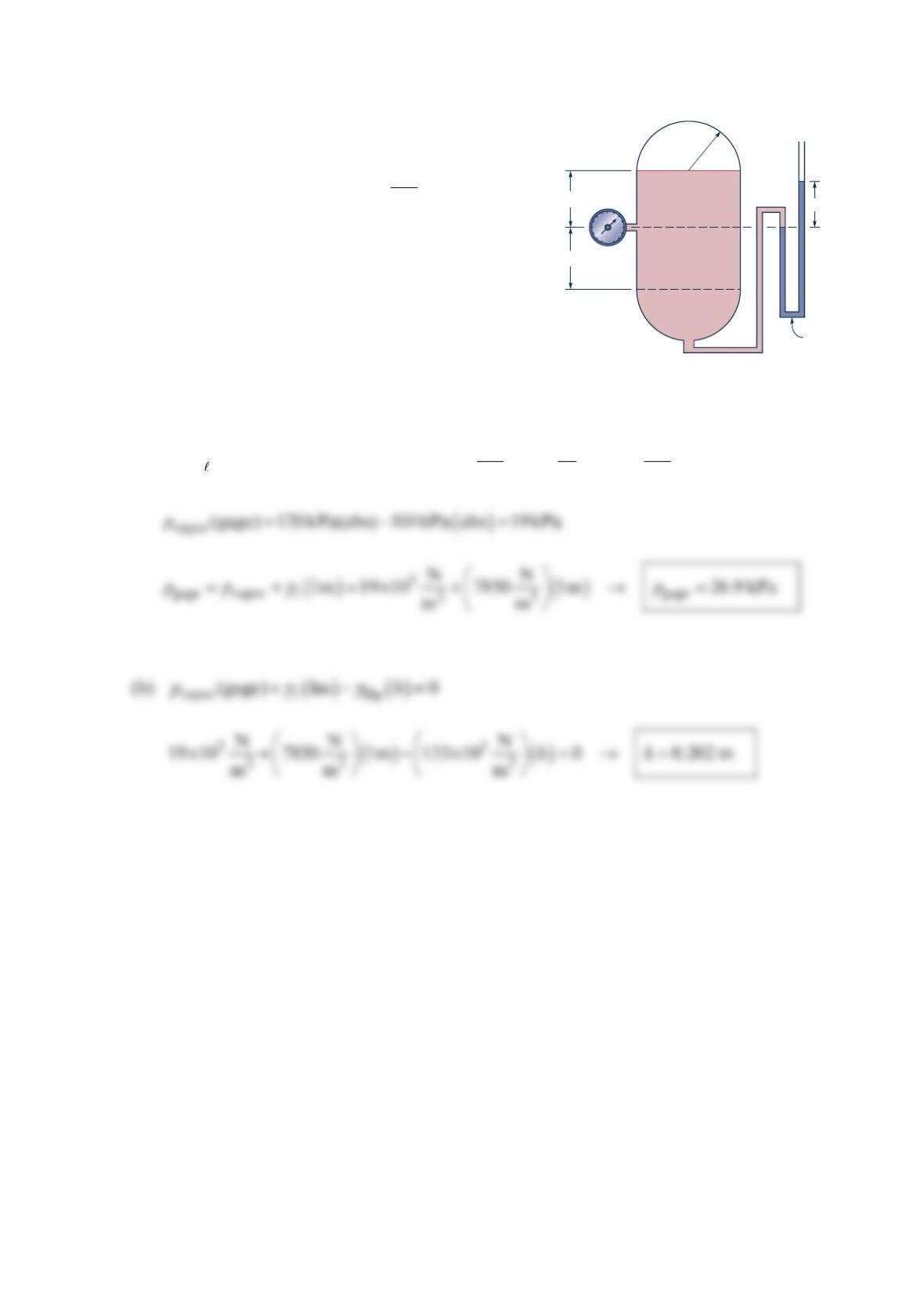
Problem 2.46
The cylindrical tank with hemispherical ends shown
in the figure below contains a volatile liquid and its
vapor. The liquid density is 3
kg
800 m, and its vapor
density is negligible. The pressure in the vapor is
()
120 kPa abs and the atmospheric pressure is
()
1
01 kPa abs . Determine: (a) the gage pressure
reading on the pressure gage, and (b) the height, h,
of the mercury, in the manometer.
Solution 2.46
(a) Let
γ
=specific weight of liquid
==
32 3
kg m N
800 9.81 7850
ms m
Liquid
Vapor 1 m
Open
Mercury
1 m
1 m
h
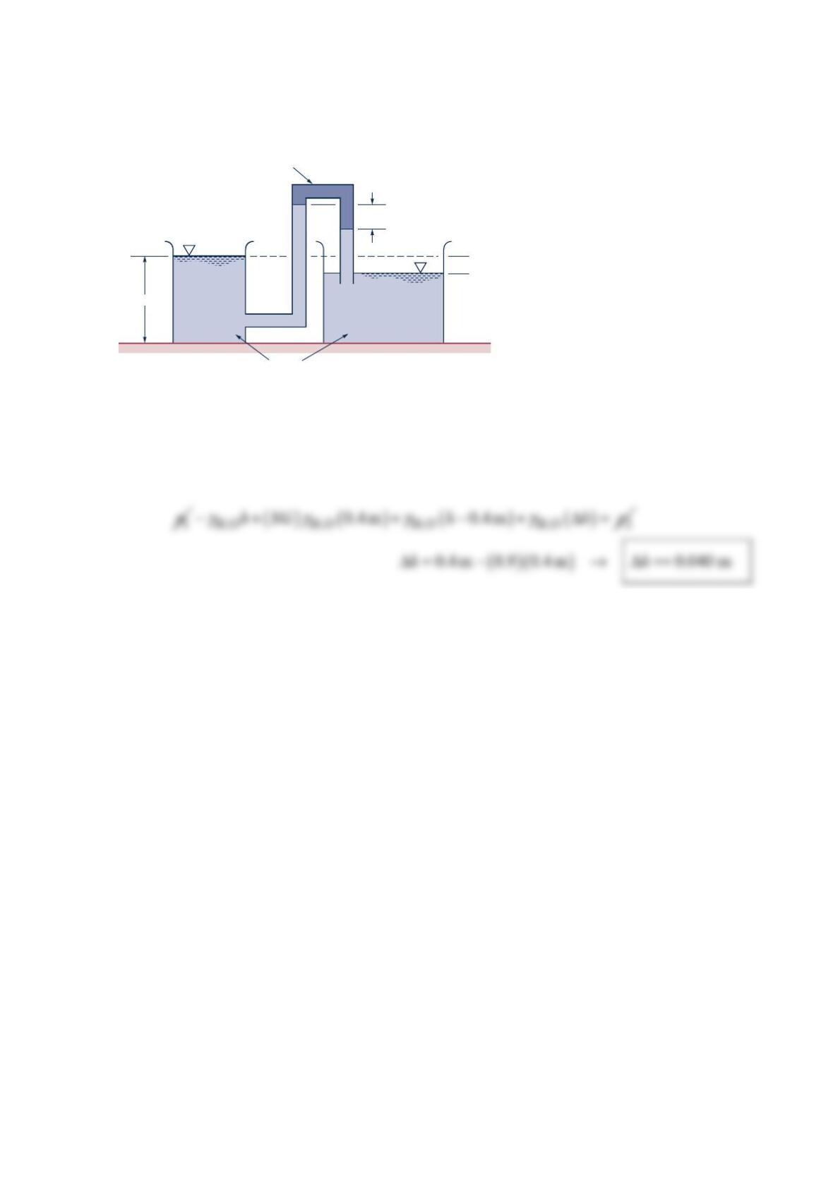
Problem 2.47
Determine the elevation difference, h
Δ
, between the water levels in the two open tanks
shown in the figure below.
Solution 2.47
Let subscript 1 indicate the surface of the left tank, and subscrip 2 the surface of the right
tank.
1 m
0.4 m
Δ
h
SG
= 0.90
Water
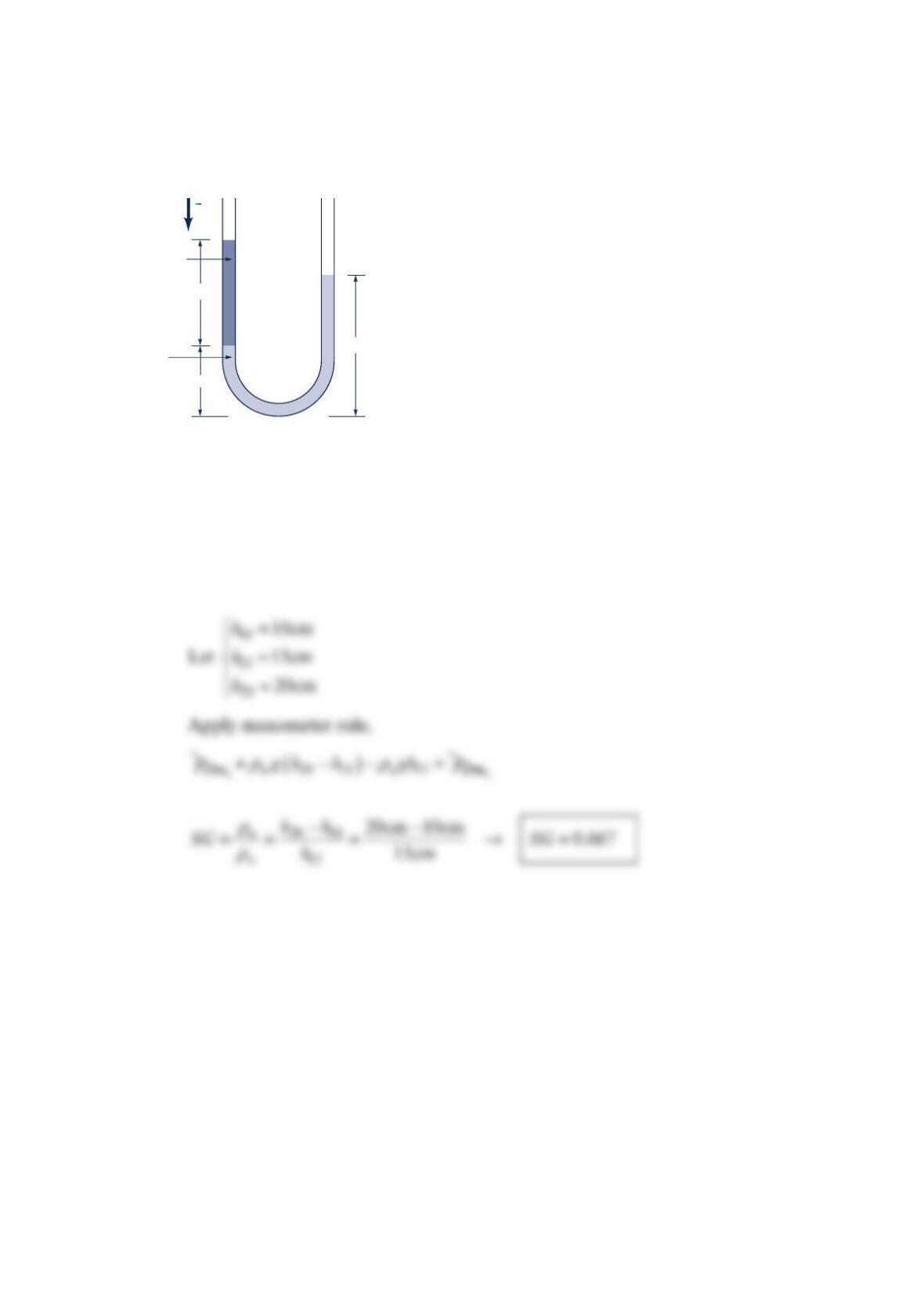
Problem 2.48
What is the specific gravity of the liquid in the left leg of the U-tube manometer shown in
the figure below?
Solution 2.48
GIVEN: Figure
FIND: Specific gravity SG of unknown fluid
SOLUTION:
Water
(
S
= 1)
15 cm
20 cm
10 cm
p
atm
p
atm
Unknown
fluid
g
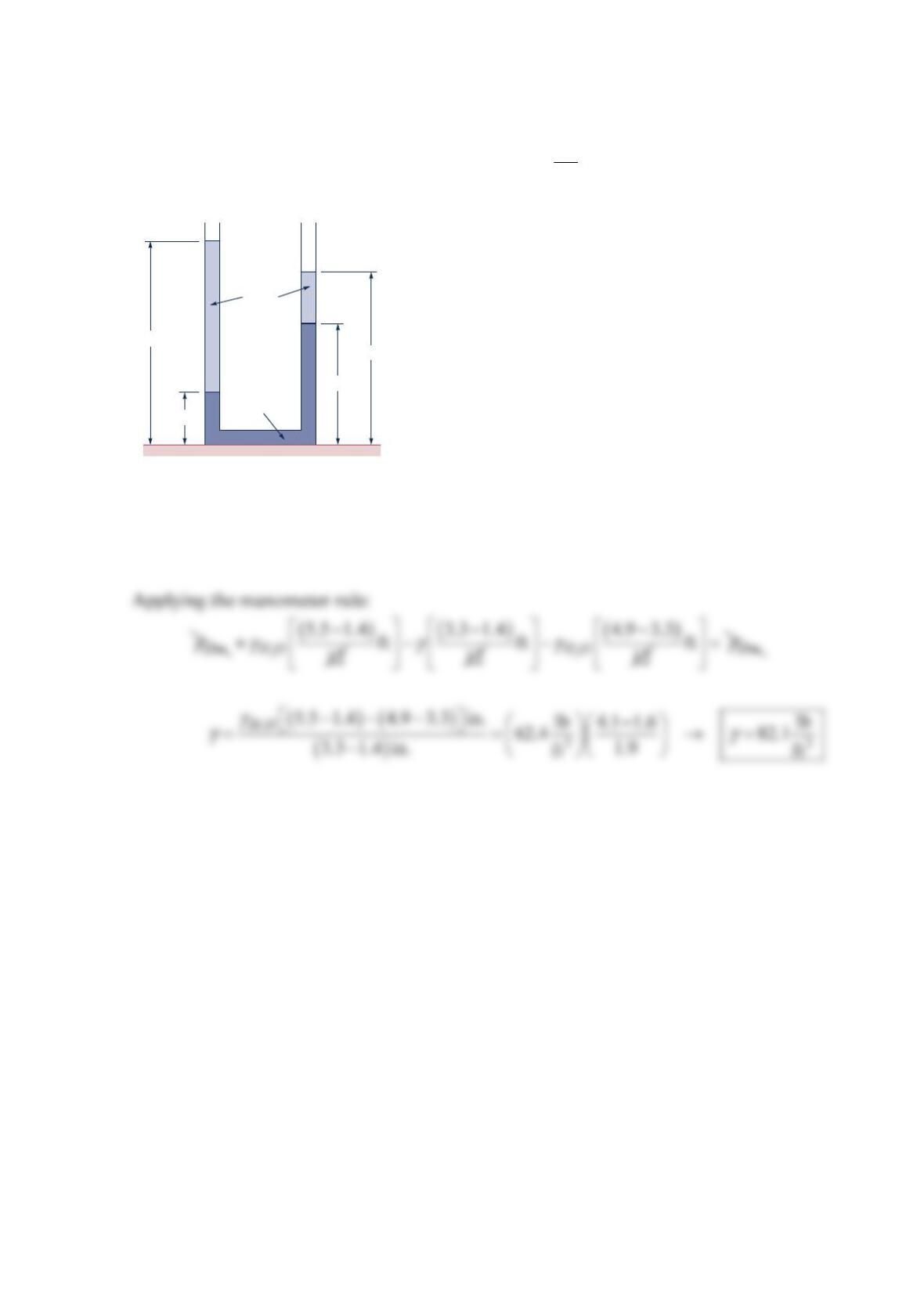
Problem 2.49
For the configuration shown in the figure below what must be the value of the specific
weight of the unknown fluid? Express your answer in 3
lb
ft .
Solution 2.49
Let
γ
be specific weight of unknown fluid.
Open Open
3.3 in.
1.4 in.
5.5 in.
4.9 in.
Water
Unknown
fluid
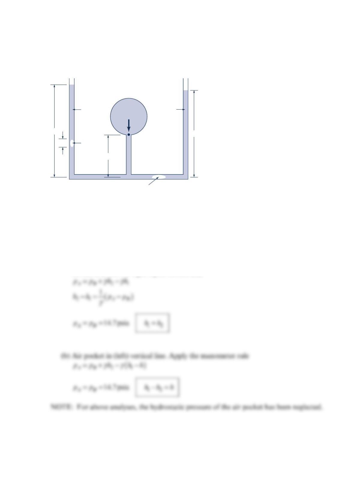
Problem 2.50
The manometer shown in the figure below has an air bubble either in (a) the right
horizontal line or (b) the left vertical leg. Find −
12
hh for both cases if =
AB
p
p.
Solution 2.50
GIVEN: Figure, manometer with small pockets of air.
FIND: =
12
hh if (a) air pocket in horizontal line and (b) air pocket in vertical line.
SOLUTION:
(a) Air pocket in horizontal line. Apply the manometer rule between the left liquid
surface (A) and the right liquid surface (B),
h
2
h
1
12″
h
Air bubble
Air bubble
Water
Water
Water
p
A
p
A
= p
B
= p
atm
= 14.7 psia
p = 16.1 psia
p
B
p
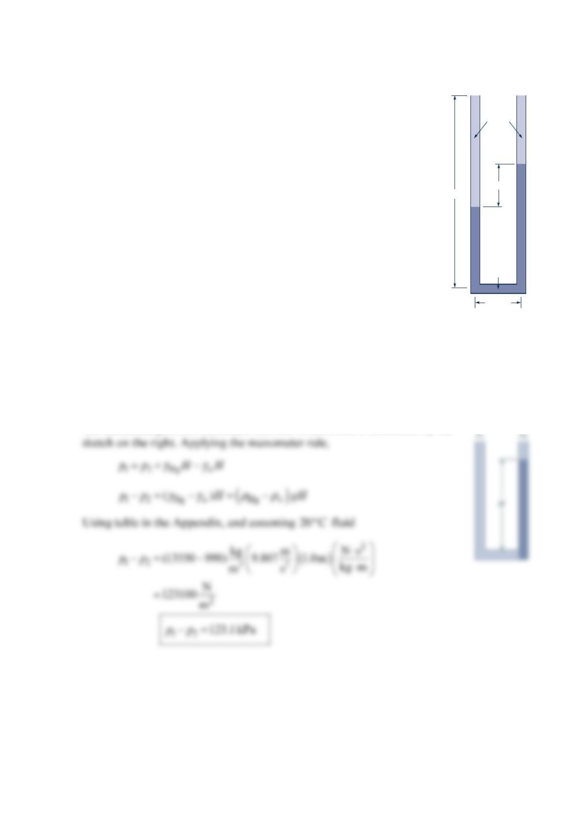
Problem 2.51
The U-tube manometer shown in the figure below has legs that are
1. 0 0 m long. When no pressure difference is applied across the
manometer, each leg has 0.40 m of mercury. What is the maximum
pressure difference that can be indicated by the manometer?
Solution 2.51
GIVEN: Manometer in the figure in the problem. With no pressure difference applied
across manometer, each mercury leg is 0.40 m high.
FIND: Maximum pressure difference that can be indicated by the manometer.
SOLUTION:
The maximum pressure difference that can be indicated is illustrated by the
1.00 m
Water
Hg
H
0.2 m
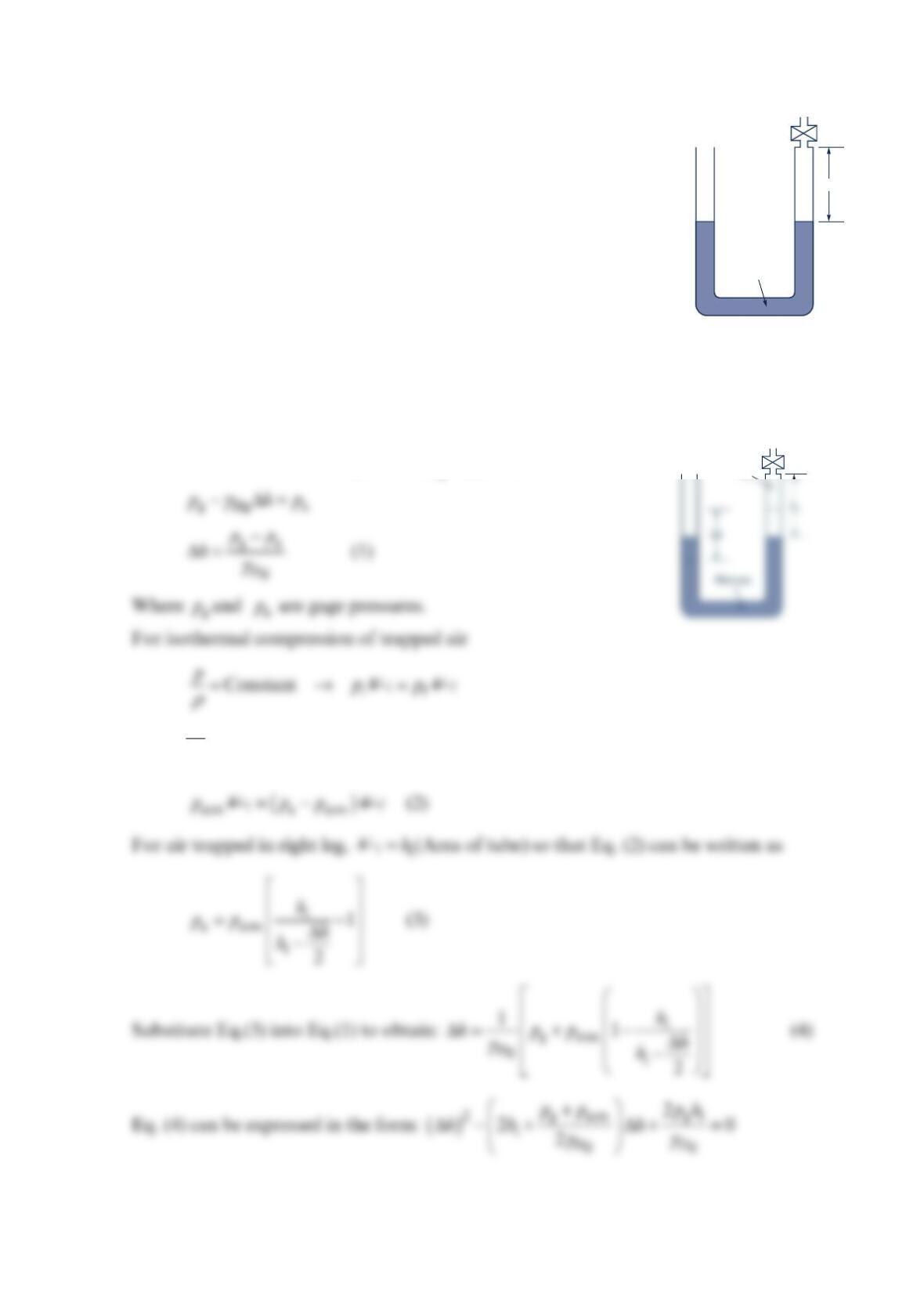
Problem 2.52
Both ends of the U-tube mercury manometer of the figure below are
initially open to the atmosphere and under standard atmospheric
pressure. When the valve at the top of the right leg is open, the level
of mercury below the valve is 1
h. After the valve is closed, air
pressure is applied to the left leg. Determine the relationship between
the differential reading on the manometer and the applied gage
pressure,
g
p
. Show on a plot how the differential reading varies with
g
p
for 1
h = 25, 50, 75, and 100 mm over the range
0 300 kPa
g
p
≤≤ . Assume that the temperature of the trapped air remains constant.
Solution 2.52
With the valve closed and a pressure,
g
p
, applied,
where Vis air volume,
p
is absolute pressure, i & f refer to initial and final states.,
respectively.
Mercury
h
i
p
g
Valve
p
g
Valve
p
a
p
p
p
p
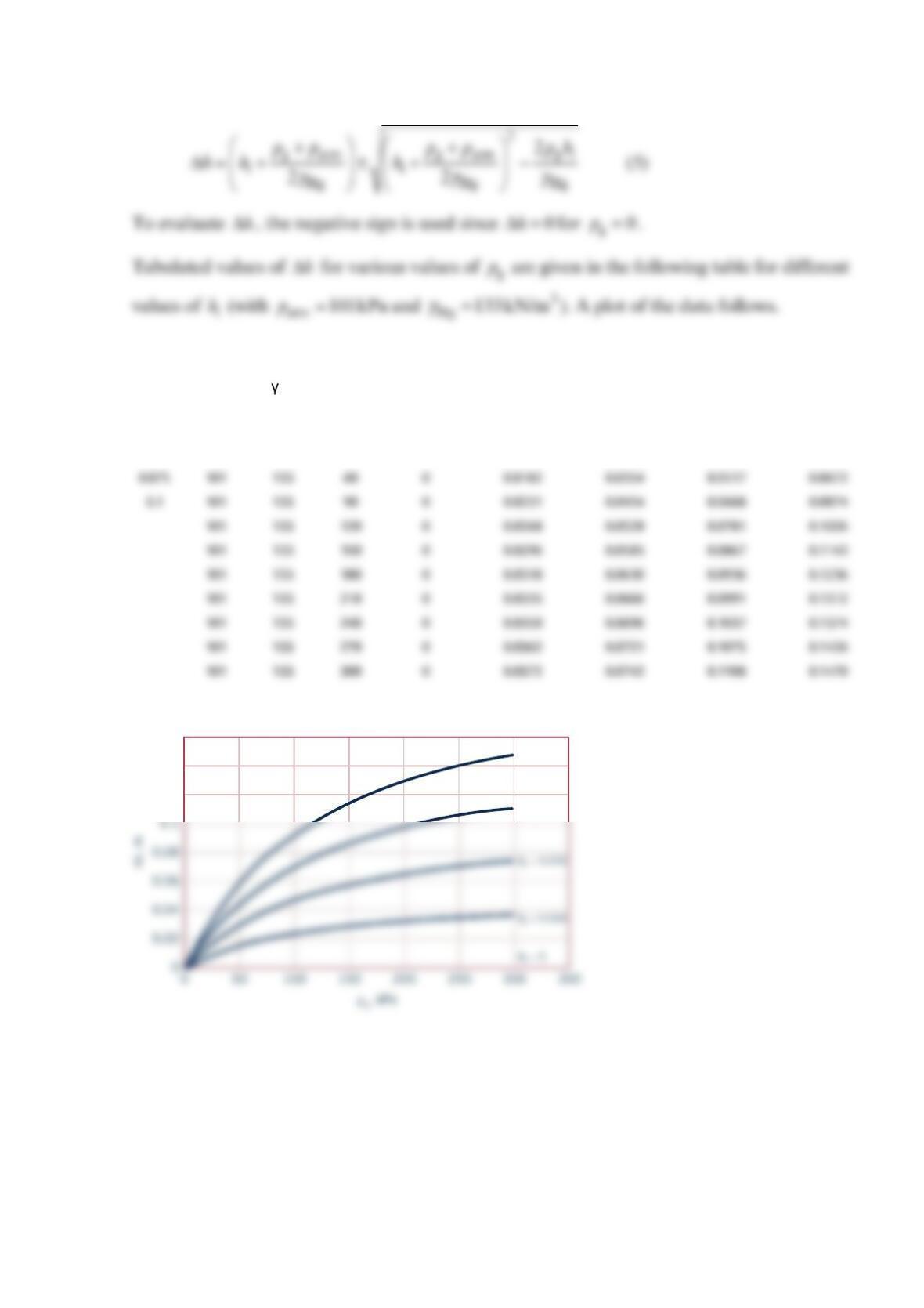
The roots of this quadratic equation are
hi (m) patm
(kPa)
hg
(kN/m3)
pg
(kPa)
Δh
(hi = 0) (m)
Δh
(hi=0.025) (m)
Δh
(hi=0.05) (m)
Δh
(hi=0.075) (m)
Δh
(hi=0.1) (m)
0.025 101 133 0 0 0 0 0 0
0.05 101 133 30 0 0.0110 0.0212 0.0306 0.0394
0.12
0.14
0.16
h
i
= 0.075
h
i
= 0.10
Problem 2.53
The inverted U-tube manometer of the figure below
contains oil ( = 0.9SG ) and water as shown. The pressure
differential between pipes A and B, AB
p
p−, is
−
5 kPa.
Determine the differential reading
h
.
Solution 2.53
A
Water
Oil
h
0.2 m
0.3 m
B
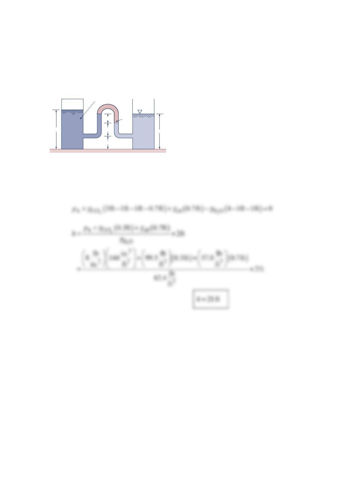
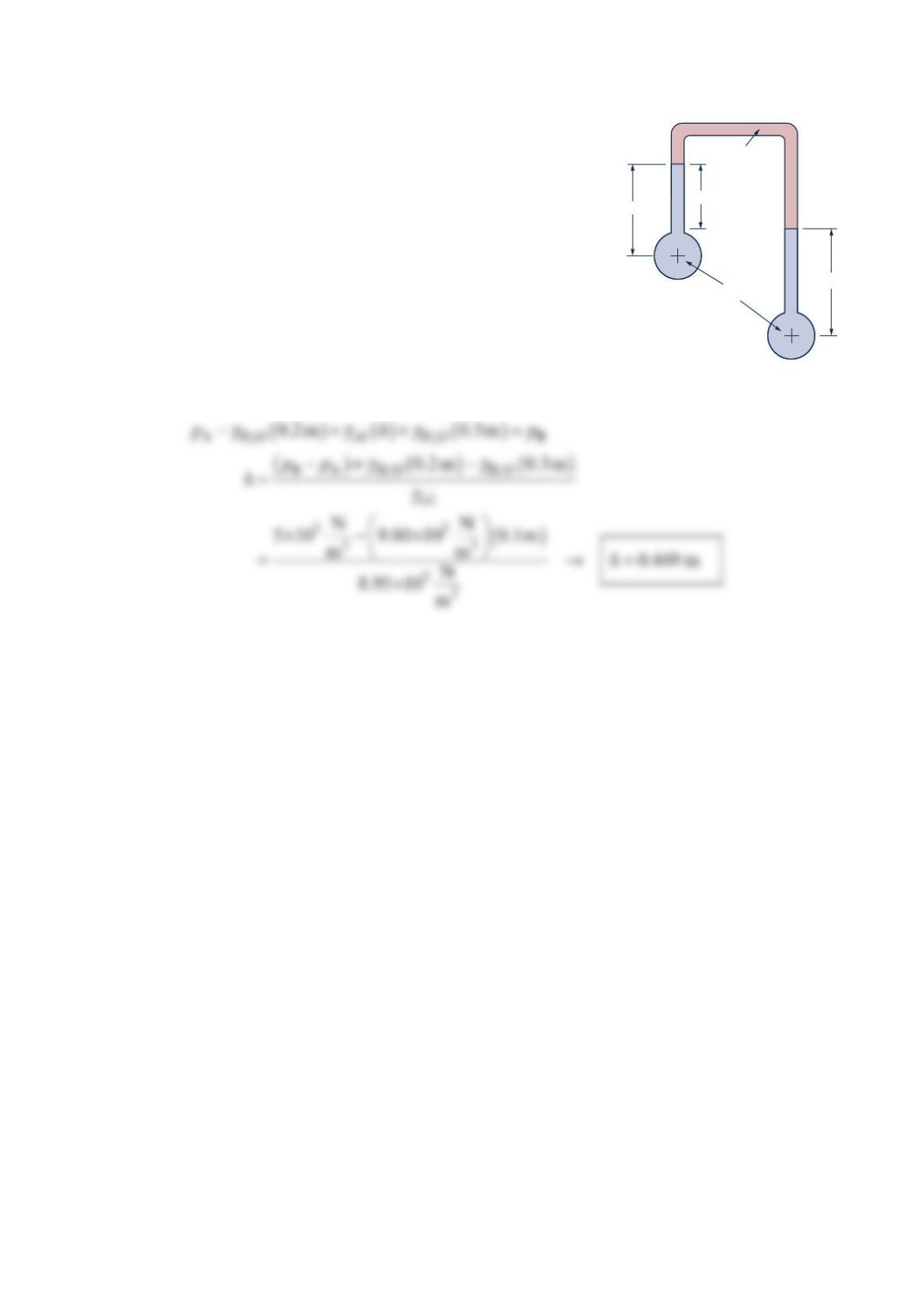
Problem 2.54
An inverted U-tube manometer containing oil ( = 0.8SG ) is located between two
reservoirs as shown in the figure below. The reservoir on the left, which contains carbon
tetrachloride, is closed and pressurized to8 psi . The reservoir on the right contains water
and is open to the atmosphere. With the given data, determine the depth of water,
h
, in the
right reservoir.
Solution 2.54
Let A
p
be the air pressure in left reserviour. Manometer equation can be written as
Carbon tetrachloride
Oil
8 psi
3 ft
h
1 ft
0.7 ft
1 ft
Water
Problem 2.55
The sensitivity Sen of the manometer shown in the figure
below can be defined as: =−
LR
h
Sen
p
p.
Three manometer fluids with the listed specific gravities S
are available:
Kerosene, =0.82SG ;
SAE 10 oil , =0.87SG ; and
Normal octane, =0.71SG .
Which fluid gives the highest sensitivity? The areas R
A and
L
A are much larger than the cross-sectional area of the
manometer tube, so Hh<< .
Solution 2.55
GIVEN: The figure in the problem, three manometer fluids, kerosene ( = 0.82SG ),
SAE 10 oil ( =0.87SG ), and normal octane ( =0.71SG ).Hh<< .
FIND: Manometer fluid that gives highest sensitivity.
SOLUTION:
Apply manometer rule,
Sensitivity maximized for f
SG closest to =1
w
SG SAE 10 oil→.
H
L
H
R
h
R
h
L
h
A
L
A
R
p
L
p
R
H
Water
W
γ
Water
Fluid
W
γ
p
p
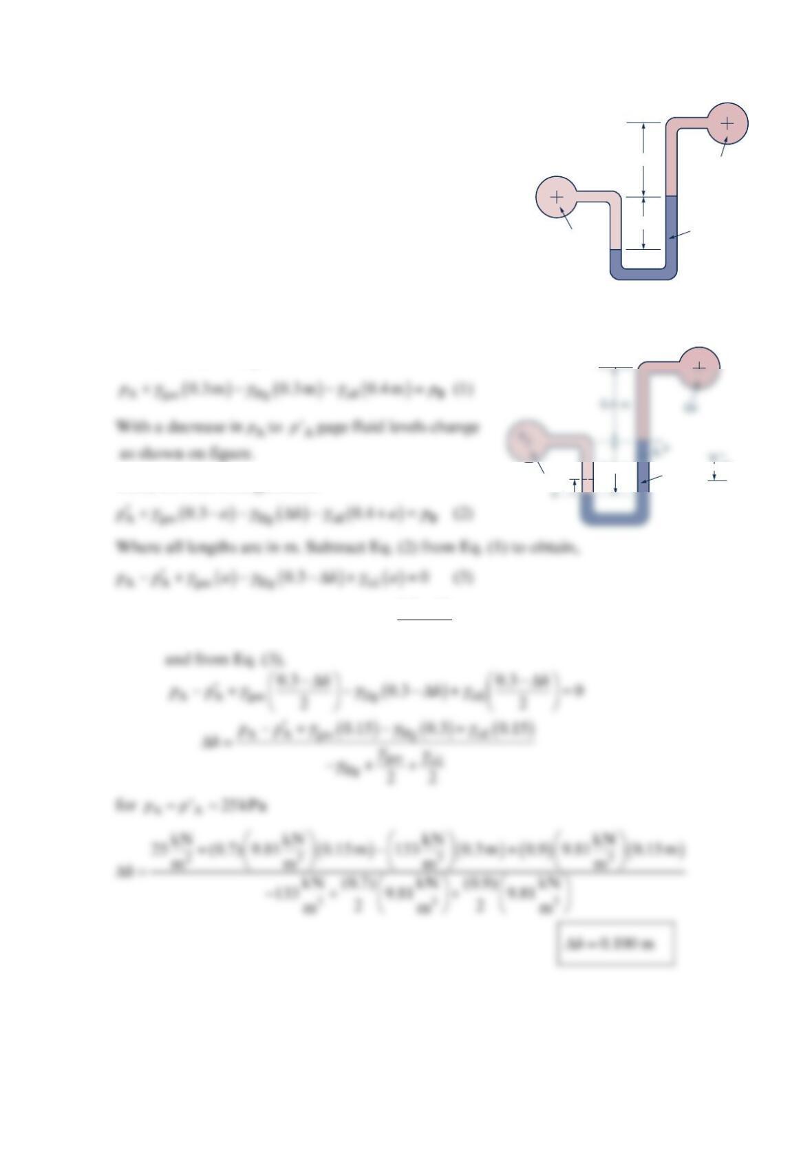
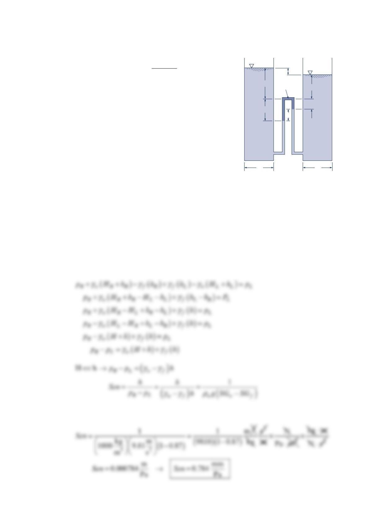
Problem 2.56
In the figure below pipe A contains gasoline ( = 0.7SG ),
pipe B contains oil ( = 0.9SG ), and the manometer fluid
is mercury. Determine the new differential reading if the
pressure in pipe A is decreased 25 kPa, and the pressure in
pipe B remains constant. The initial differential reading is
0.30 m as shown.
Solution 2.56
For the initial configuration:
Thus, for final configuration:
Since
2
0.3ah+Δ = (see figure) then, 0.3
2
h
a
−Δ
=
A
B
Oil
Mercury
Gasoline
0.4 m
0.3 m
B
∆h
Mercury
Gasoline
0.3 m
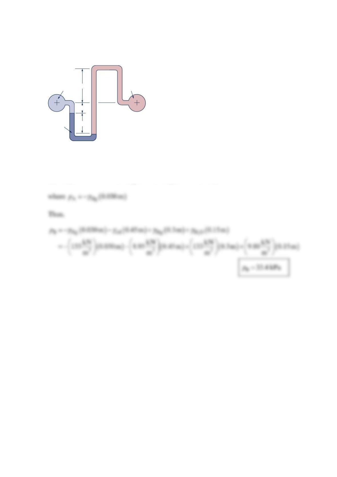
Problem 2.57
The mercury manometer of the figure below indicates a differential reading of 0.30 m when
the pressure in pipe A is 30-mm Hg vacuum. Determine the pressure in pipe B.
Solution 2.57
()()()
γγγ
+−−=
2
Boil Hg HO A
0.15 m+0.30 m 0.3m 0.15 m
p
p
Water
A
0.50 m
0.30 m
0.15 m
B
Mercury
Oil
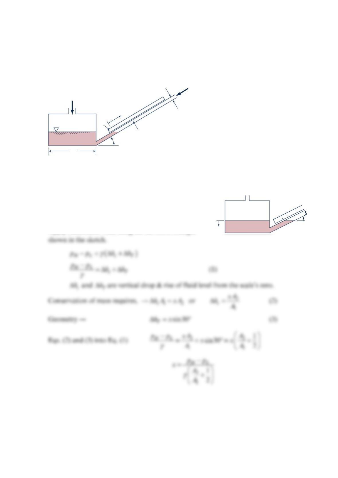
Problem 2.58
Consider the cistern manometer shown in the figure below. The scale is set up on the basis
that the cistern area 1
A is infinite. However, 1
A is actually 50 times the internal cross-
sectional area 2
A of the inclined tube. Find the percentage error (based on the scale
reading) involved in using this scale.
Solution 2.58
GIVEN: The figure in the problem with 12
50
A
A=.
FIND: Percent error in using a scale based on 1
A as
infinite.
SOLUTION:
Apply manometer rule, using the elevation changes
Air
Air
= 30
°
0
Oil,
S
= 0.85
A
1
A
2
p
L
p
H
x
θ
0
p
H
p
L
∆h
T
∆
h
c