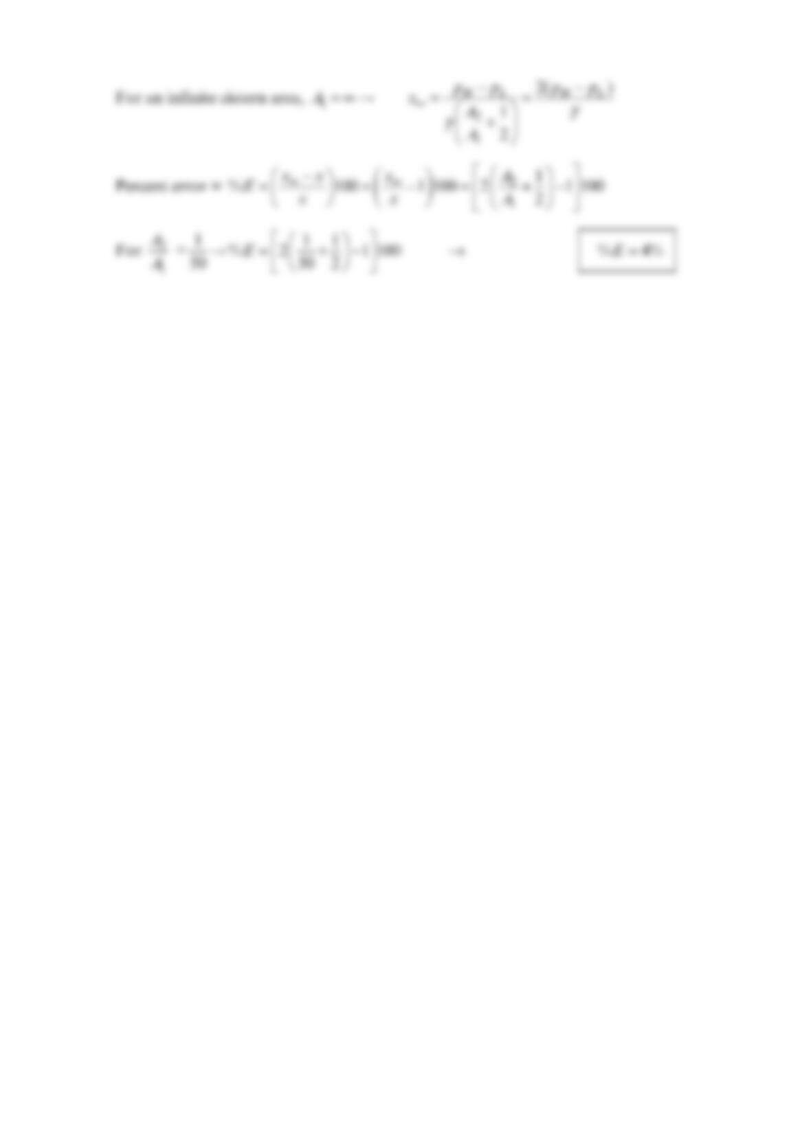
Problem 2.59
The cistern shown in the figure below has a diameter D that is 4 times the diameter d of
the inclined tube. Find the drop in the fluid level in the cistern and the pressure difference
(−
AB
p
p) if the liquid in the inclined tube rises =20 in.l The angle
θ
is °20 . The fluid’s
specific gravity is 0.85 .
Solution 2.59
GIVEN: The figure in the problem, 4
D
d=, =20in.l, 20º
θ
=,
S
0.85=.
FIND: −
AB
p
p
SOLUTION:
Conservation of mass requires,
0
D
θ
p
A
dp
B
ℓ
p
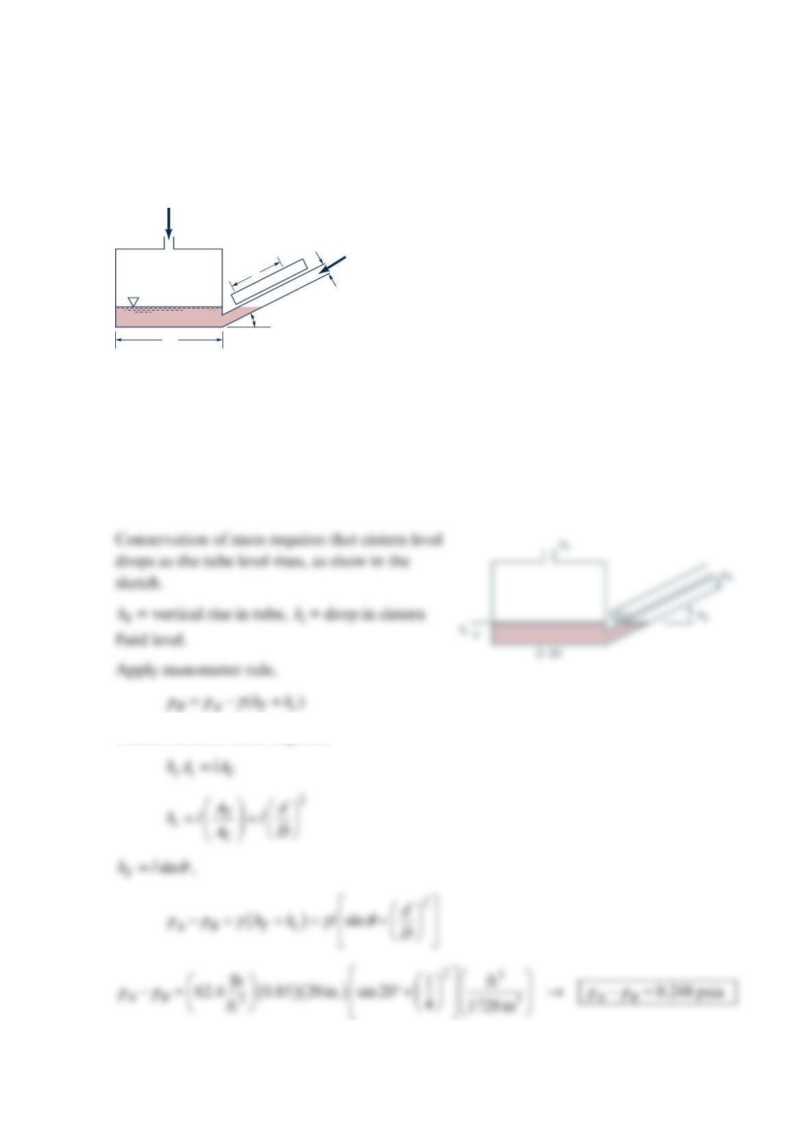
Problem 2.60
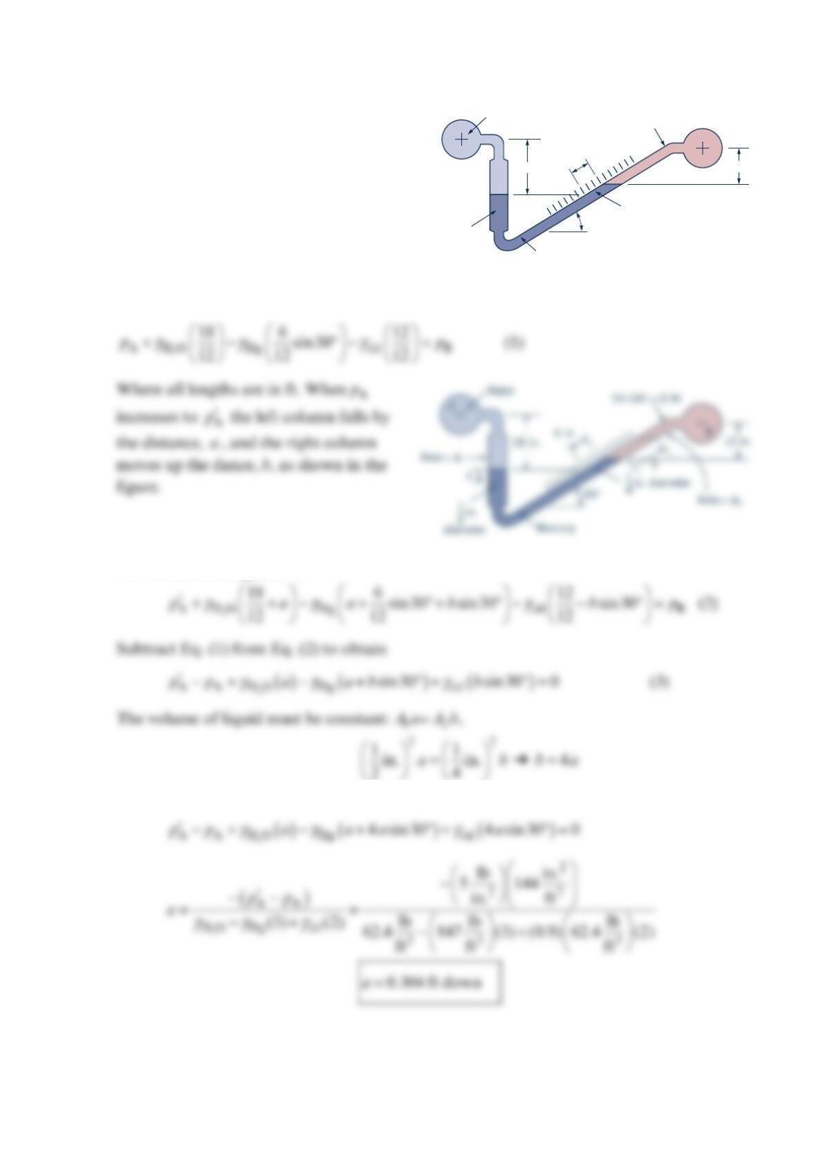
The inclined differential manometer of the figure below
contains carbon tetrachloride. Initially the pressure
differential between pipes A and B, which contain a brine
(= 1. 1SG ), is zero as illustrated in the figure. It is
desired that the manometer give a differential reading of
12 in. (measured along the inclined tube) for a pressure
differential of 0.1 psi . Determine the required angle of
inclination,
θ
.
Solution 2.60
When −
AB
p
p is increased to ′′
−
AB
p
pthe left column falls a distance,
a
, and the right
column rises a distance b along the inclined tube as shown in the figure. For this final
configuration:
The differential reading, h
Δ
, along the tube is
Δ
p
Δ
A
Brine
Brine
12 in.
Carbon
tetrachloride
A
B
θ
p
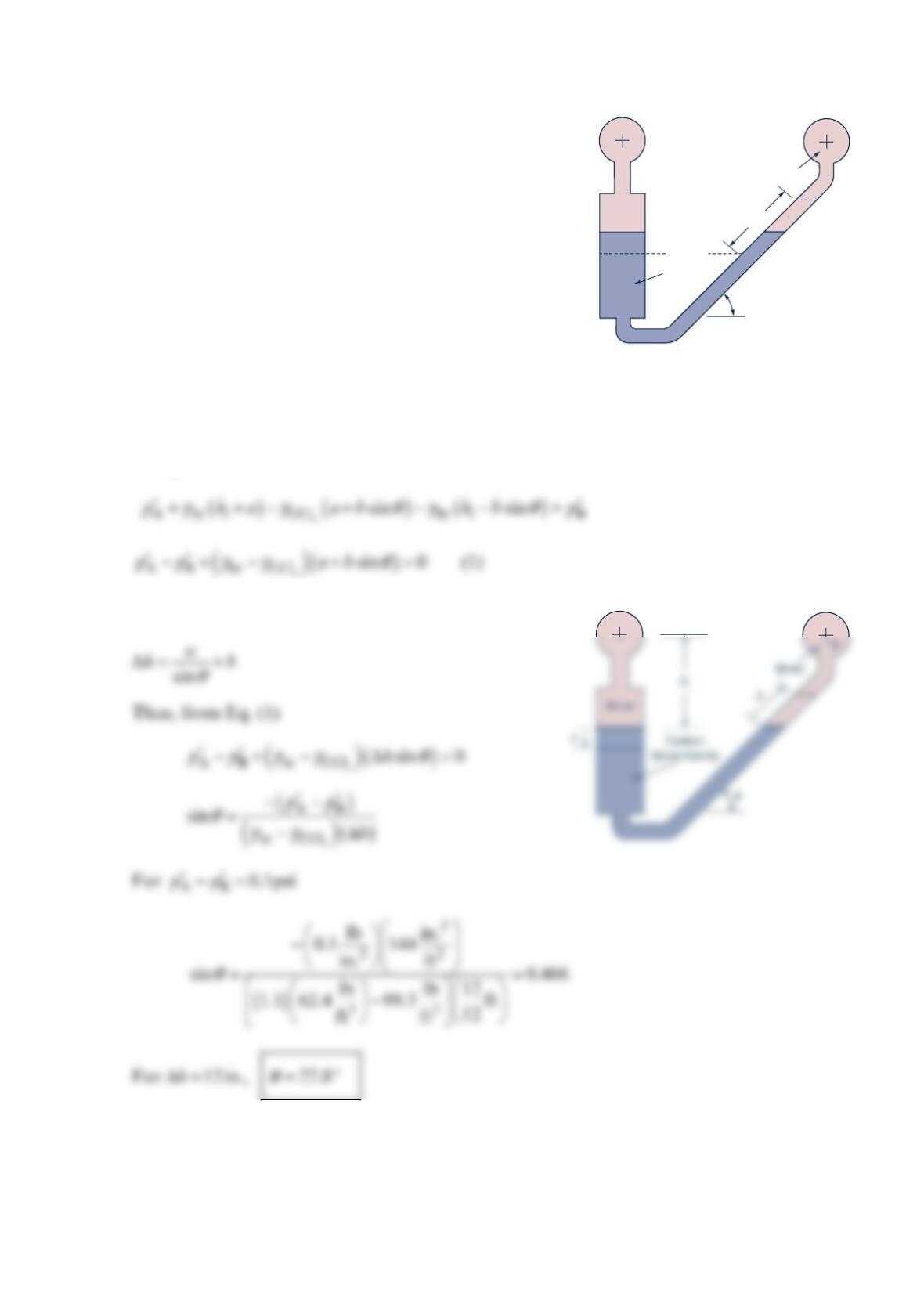
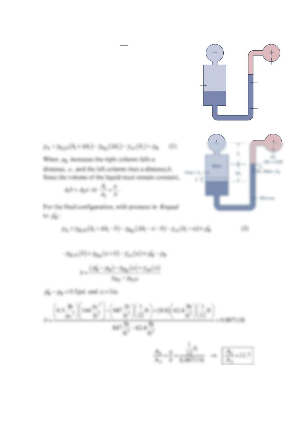
Problem 2.61
Determine the new differential reading
along the inclined leg of the mercury
manometer of the figure below, if the
pressure in pipe A is decreased 10 kPa and
the pressure in pipe B remains unchanged.
The fluid in A has a specific gravity of 0.9
and the fluid in B is water.
Solution 2.61
For the initial configuration:
For the final configuration:
100 mm
50 mm
Mercury
Water
SG = 0.9
30°
A
B
80 mm
Mercury
Problem 2.62
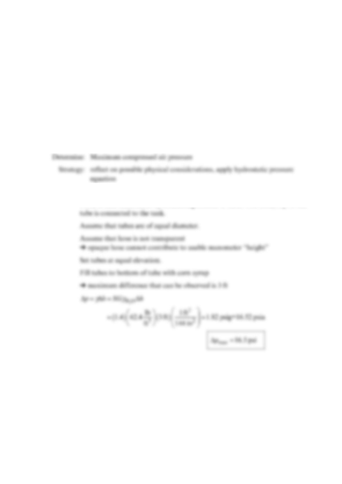
A student needs to measure the air pressure inside a compressed air tank but does not have
ready access to a pressure gage. Using materials already in the lab, she builds a U-tube
manometer using two clear 3-ft- long plastic tubes, flexible hoses, and a tape measure. The
only readily available liquids are water from a tap and a bottle of corn syrup. She selects the
corn syrup because it has a larger density ( =1. 4SG ). What is the maximum air pressure, in
p
sia, that can be measured?
Solution 2.62
Known: two 3-ft– long clear tubes, unknown length flexible hose, tape measure,
corn syrup ( =1. 4SG )
Solution:
Form u-tube manometer by connecting bottom of tubes with hose; top of one
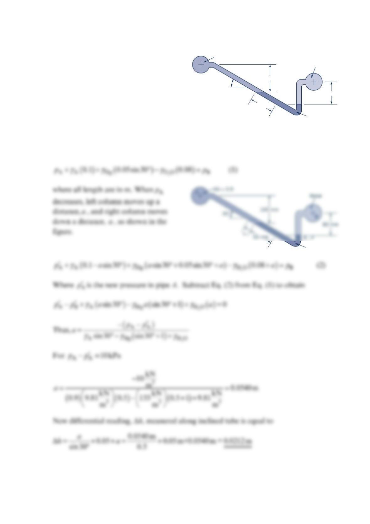
Problem 2.63
Determine the ratio of areas, 1
2
A
A, of the two
manometer legs of the figure below if a change in
pressure in pipe B of 0.5 psi gives a corresponding
change of 1 in. in the level of the mercury in the
right leg. The pressure in pipe A does not change.
Solution 2.63
For the initial configuration (see the figure):
Subtract Eq. (1) from Eq. (2) to obtain
A B
Water
Area
= A
1
Area
= A
2
Mercury
Oil
(SG = 0.8)
Problem 2.64
Determine the change in the elevation of the
mercury in the left leg of the manometer of
the figure below as a result of an increase in
pressure of 5 psi in pipe A while the pressure
in pipe B remains constant.
Solution 2.64
For the initial configuration:
For the final configuration:
Thus, Eq. (3) can be written as
Water
Mercury
30°
Oil (
SG
= 0.9)
18 in. 6 in.
-in.-diameter
1
_
4
-in.-
diameter
1
_
2
12 in.
A
B
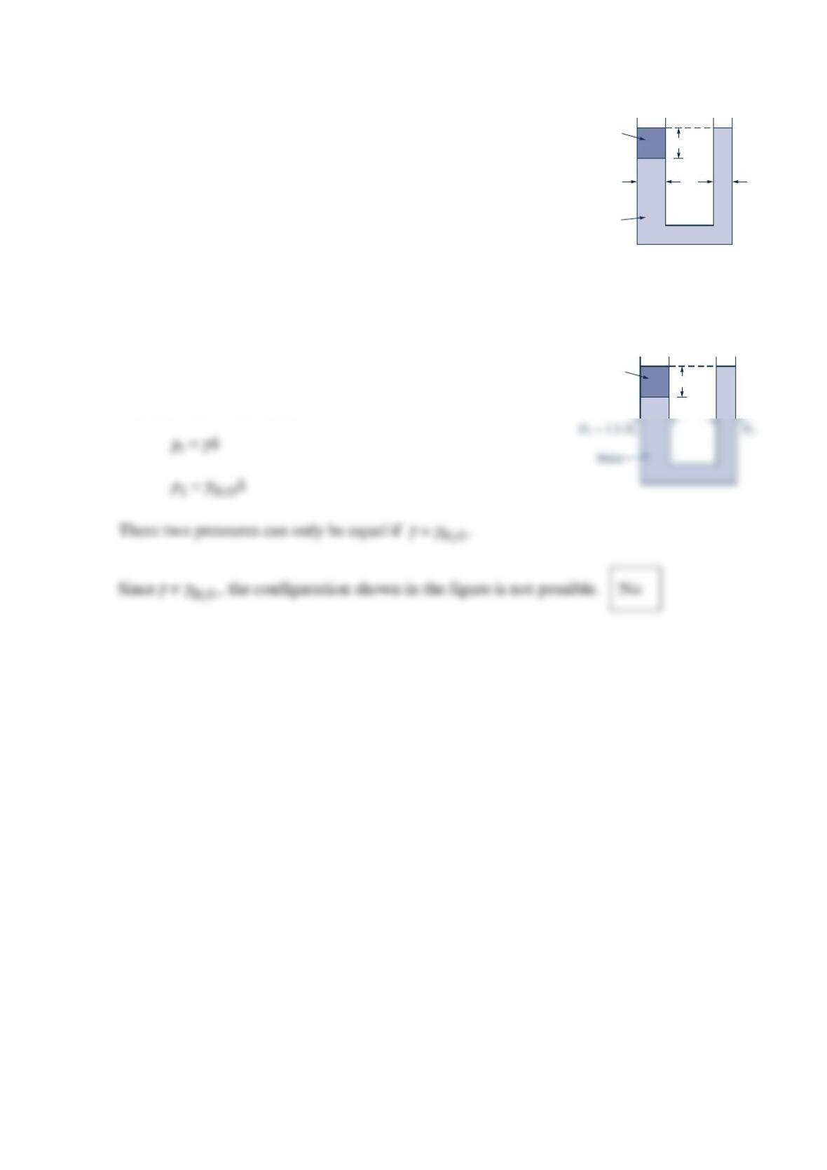
Problem 2.65
The U-shaped tube shown in the figure below initially contains
water only. A second liquid with specific weight,
γ
, less than
water is placed on top of the water with no mixing occurring.
Can the height,
h
, of the second liquid be adjusted so that the
left and right levels are at the same height? Provide proof of
your answer.
Solution 2.65
The pressure at point (1) must be equal to the pressure at point
(2) since the pressures at equal elevations in a continuous mass
of fluid must be the same.
Water
D
1
= 1.5
D
2
D
2
h
γ
h
γ
γ
D
0.060
0.070
0.080
Problem 2.66
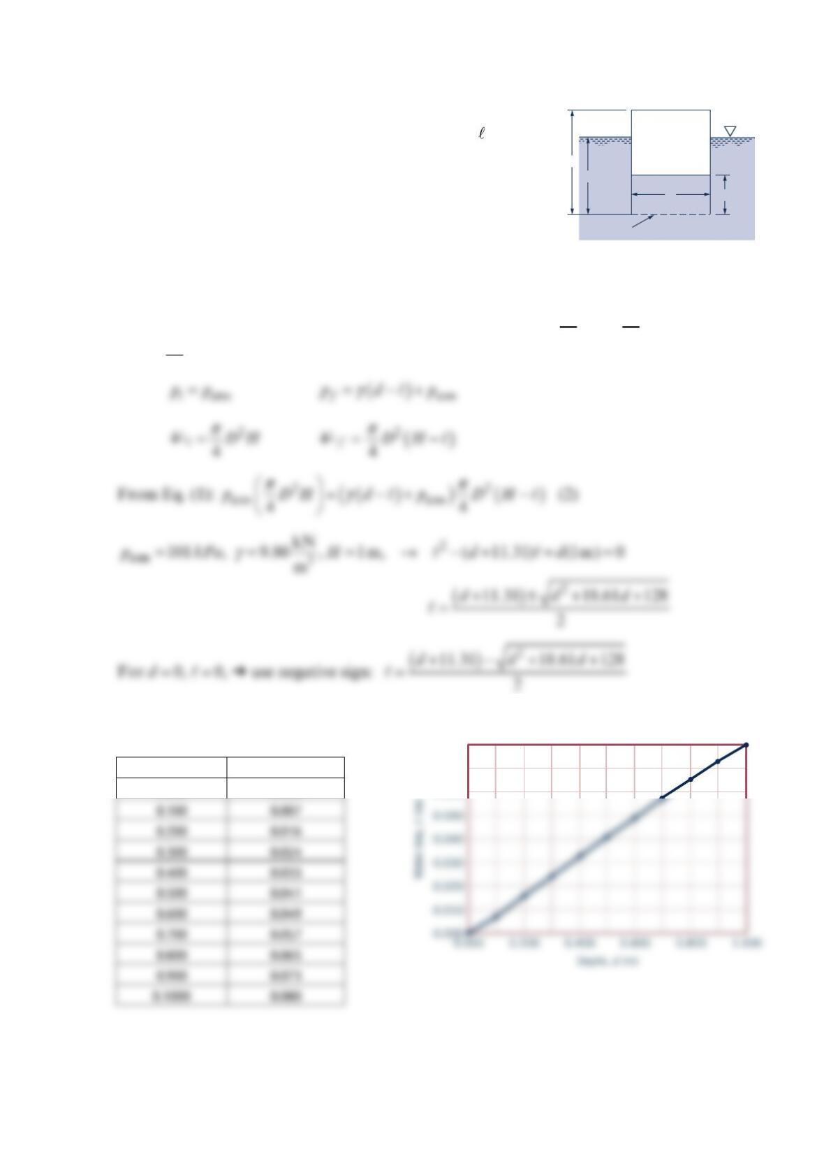
An inverted hollow cylinder is pushed into the water as is
shown in the figure below. Determine the distance, , that the
water rises in the cylinder as a function of the depth,
d
, of the
lower edge of the cylinder. Plot the results for0 dH≤≤,
when His equal to 1 m. Assume the temperature of the air
within the cylinder remains constant.
Solution 2.66
For constant temperature compression within the cylinder, i
pV =
if
p
Vf (1)
where Vis the air volume, and iand frefer to the initial and final states, respectively
p
p
Tabulated data with the corresponding plot are shown below.
Depth, d (m) Water rise, l (m)
0.000 0.000
Water
Open end
Dℓ
d
H
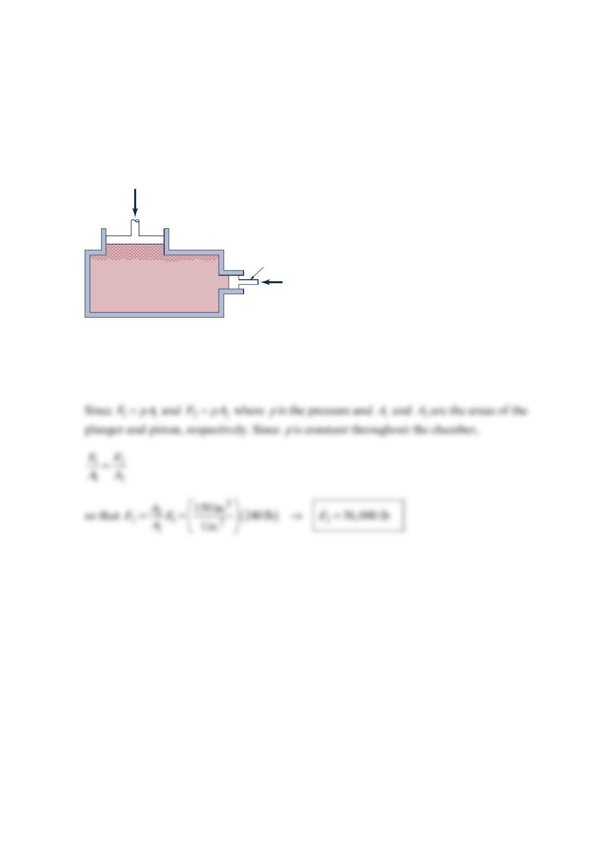
Problem 2.68
The basic elements of a hydraulic press are shown in the figure below. The plunger has an
area of 2
1in. , and a force, 1
F, can be applied to the plunger through a lever mechanism
having a mechanical advantage of 8 to 1. If the large piston has an area of 2
150 in. , what
load, 2
F
, can be raised by a force of 30 lb applied to the lever? Neglect the hydrostatic
pressure variation.
Solution 2.68
A force of 30 lb applied to the level results in a plunger force, 1
F, of 1(8)(30) 240 lb
F
==.
Plunger
F
2
F
1
Hydraulic fluid
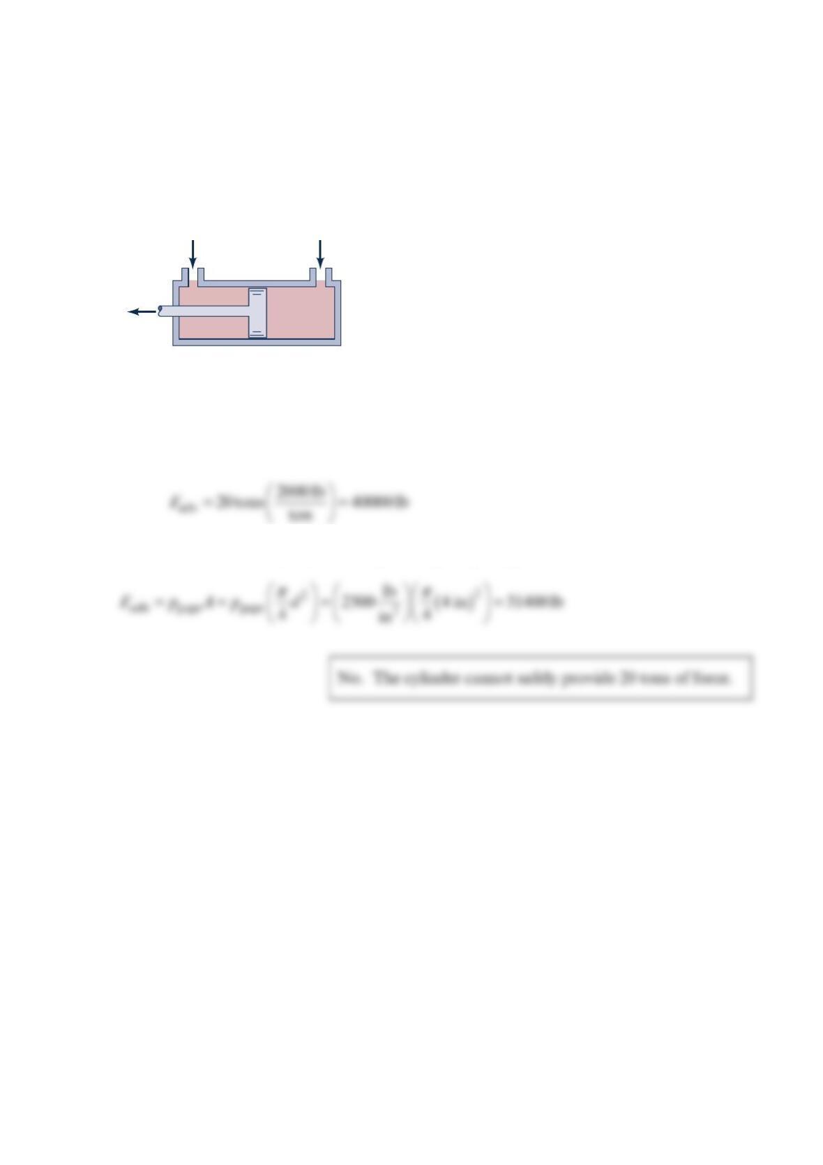
Problem 2.69
The hydraulic cylinder shown in the figure below, with a 4-in.- diameter piston, is
advertised as being capable of providing a force of 20 tons
F
=. If the piston has a design
pressure (the maximum pressure at which the cylinder should safely operate) of 2
2500 lb/in ,
gage, can the cylinder safely provide the advertised force?
Solution 2.69
Assuming a “ton” is a “short ton”, the advertised force is
The maximum force that can be safely developed by the piston is
= 2500 Ib/in.
2
gage
p
atm
p
max
F
8.00
W = 0.0522
θ
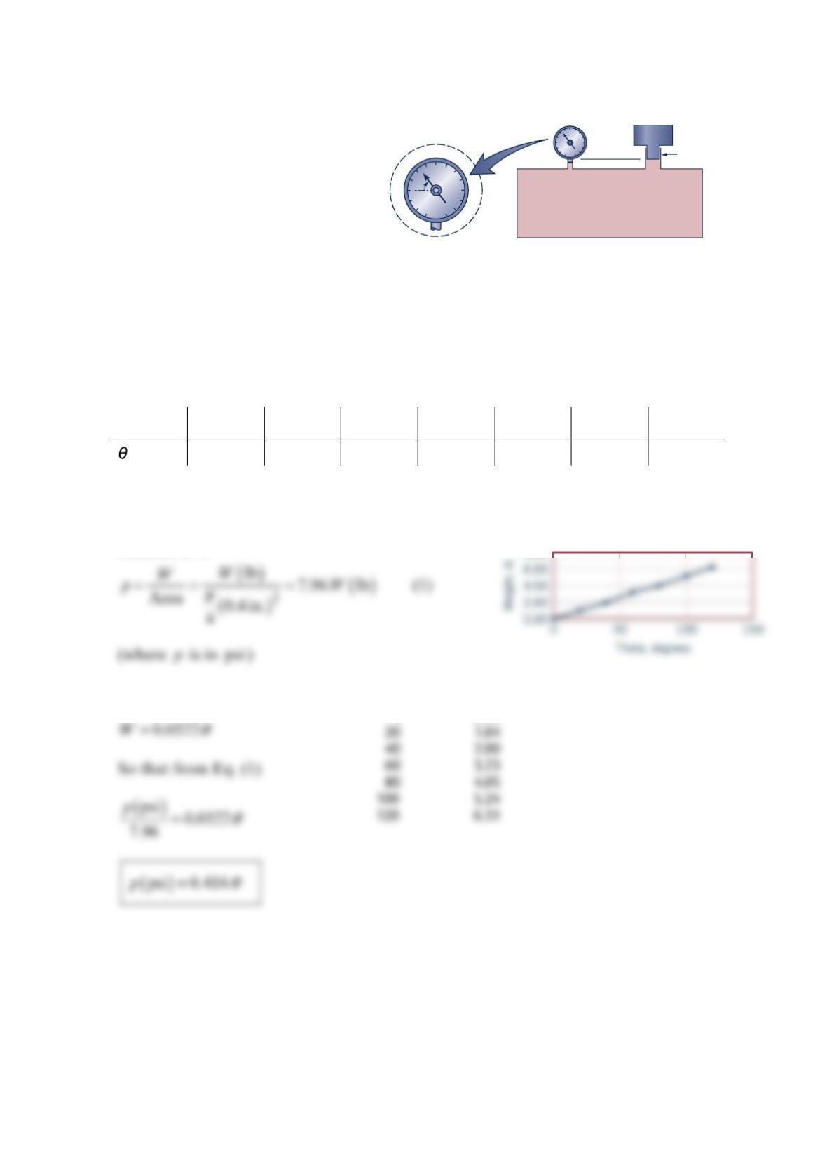
Problem 2.70
A Bourdon gage is often used to
measure pressure. One way to
calibrate this type of gage is to use
the arrangement shown in the figure
below (a). The container is filled
with a liquid and a weight,
W
,
placed on one side with the gage on
the other side. The weight acting on
the liquid through a 0.4-in. -diameter opening creates a pressure that is transmitted to the
gage. This arrangement, with a series of weights, can be used to determine what a change in
the dial movement,
θ
, in the figure below (b), corresponds to in terms of a change in
pressure. For a particular gage, some data are given below. Based on a plot of these data,
determine the relationship between
θ
and the pressure,
p
, where
p
is measured in
p
si.
(lb) 0 1.04 2.00 3.23 4.05 5.24 6.31
(deg.) 0 20 40 60 80 100 120
Solution 2.70
From graph
Theta, de
g
W
, lb
00.00
Bourdon gage
(b)(a)
𝒲
Liquid
0.4-in.-diameter
θ
p
Problem 2.71
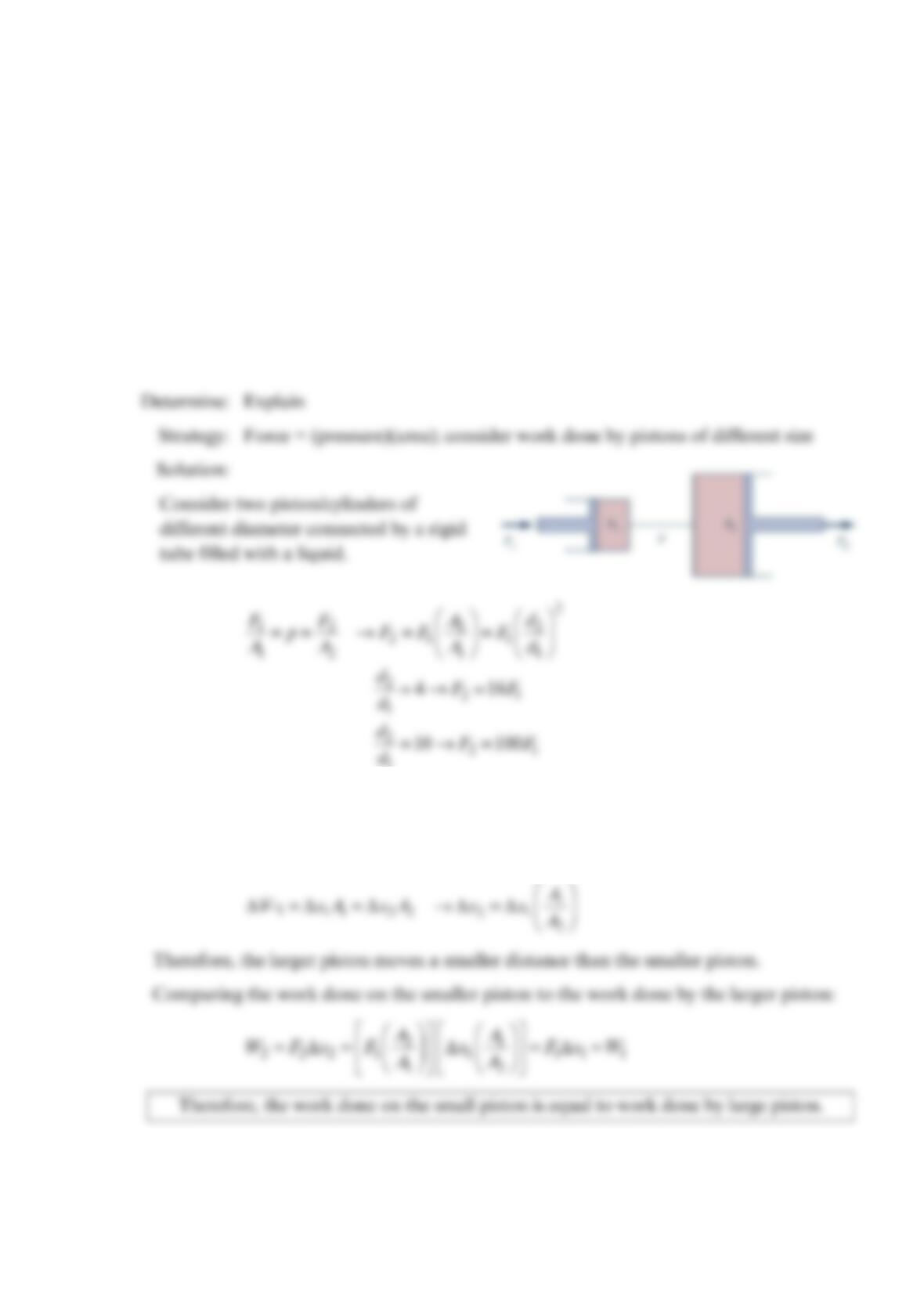
A bottle jack allows an average person to lift one corner of a 4000-lb automobile
completely off the ground by exerting less than 20 lb of force. Explain how a 20-lb force
can be converted into hundreds or thousands of pounds of force, and why this does not
violate our general perception that you cannot get something for nothing (a somewhat
loose paraphrase of the first law of thermodynamics). Hint: Consider the work done by
each force.
Solution 2.71
Known: 20 lb applied force lifts corner of 4,000 lb automobile
1
Therefore producing the required force multiplication is not difficult.
Assuming all solid boundaries are rigid, the volume pushed out of the small cylinder
must equal that entering the large cylinder.
Problem 2.72
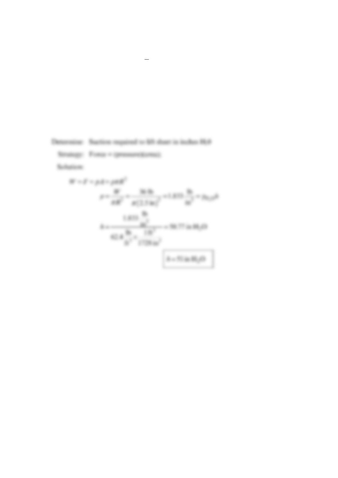
Suction is often used in manufacturing processes to lift objects to be moved to a new
location. A 4-ft by 8-ft sheet of 1-in.
2 plywood weighs approximately 36 lb . If the
machine’s end effector has a diameter of 5 in., determine the suction pressure required to
lift the sheet, expressed in inches of 2
HO
suction.
Solution 2.72
Known: =36 lbW; =
CUP 5 in.D
Problem 2.73
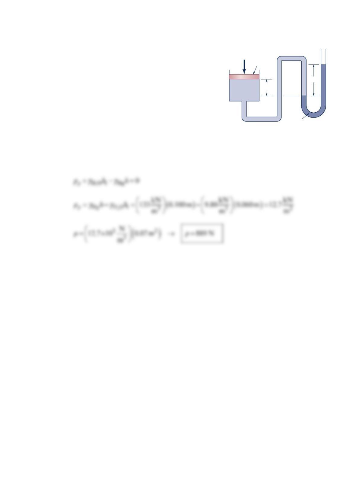
A piston having a cross-sectional area of 2
0.07 m is
located in a cylinder containing water as shown in the
figure below. An open U-tube manometer is connected
to the cylinder as shown. For =
1 60 mmhand
100 m
m
h
=, what is the value of the applied force, P,
acting on the piston? The weight of the piston is
negligible.
Solution 2.73
For equilibrium, =
p
P
p
pA where
p
p
is the pressure acting on piston and P
Ais the area of
the piston. Also,
Piston
P
h
h
1
Water
Mercury
Problem 2.74
A 6-in.-diameter piston is located within a cylinder that is connected to a 1-in.
2-diameter
inclined-tube manometer as shown in the
figure below. The fluid in the cylinder and
the manometer is oil (specific weight =
3
59 lb/ft ). When a weight,
W, is placed on
the top of the cylinder, the fluid level in the
manometer tube rises from point (1) to (2).
How heavy is the weight? Assume that the
change in position of the piston is negligible.
Solution 2.74
With piston alone let pressure on face of
piston =
p
p
. Manometer equation becomes
With weight added pressure
p
p
increases to ′
p
p
where
Subtract Eq. (1) from Eq. (2) to obtain
𝒲
Piston
Oil
(1)
(2)
30°
6 in.
𝒲
Piston
(1)
(2)
6 in.
h
1
Problem 2.75
The container shown in the figure below has square cross sections.
Find the vertical force on the horizontal surface, ABCD.
Solution 2.75
The vertical force on surface ABCD is equal to the weight of the
imaginary fluid above ABCD as show on the picture on the right, so
Water
2
2
4
1
_
2
AD
EF
BC
″
41
_
2
″
r
R
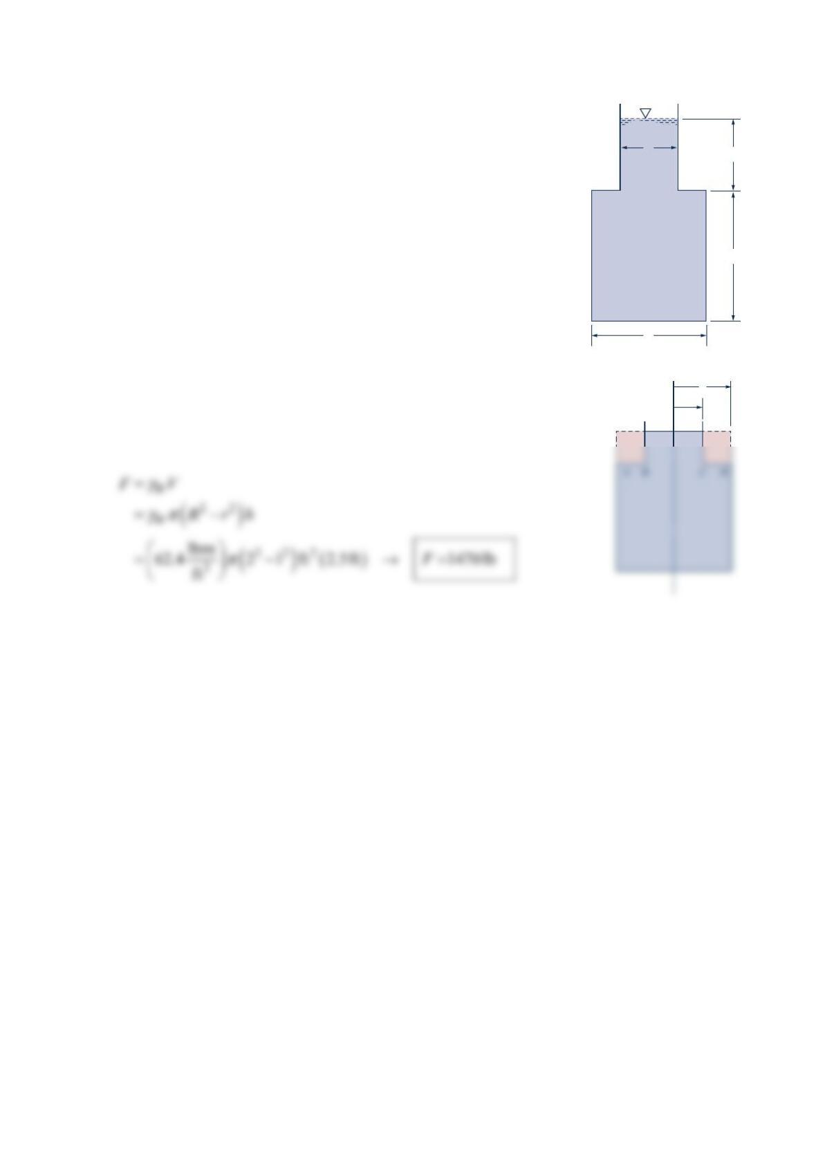
Problem 2.76
Find the weight W needed to hold the wall shown in the figure below upright. The wall is
10 m wide.
Solution 2.76
The hydrostatic force Fon the wall is found from
The force F is located one-third of the water depth from the bottom of the water.
Summing moments about the pinned joint,
Assuming no friction between the rope and the pulley,
DISCUSSION
Note that the atmospheric pressure acts on both sides of the wall.
Therefore, the forces due to atmospheric pressure are equal and opposite, and cancel.
3 m
4 m
𝒲
Water
Wall
Pinned
F
w
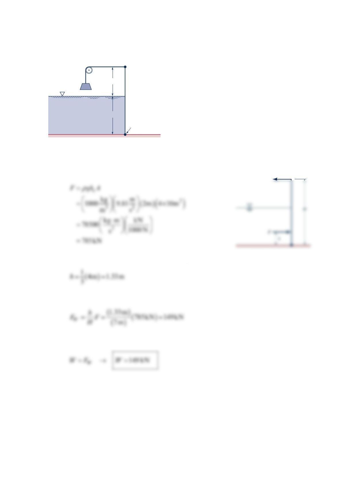
Problem 2.77
Determine the magnitude and direction of the force that must
be applied to the bottom of the gate shown in the figure below
to keep the gate closed.
Solution 2.77
The hydrostatic force on the gate is
The location of the force F is
c
Using Appendix,
Summing moments about the hinge,
0.8 m
2.1 m
Water
Hinge
2-m-wide
gate
F
h
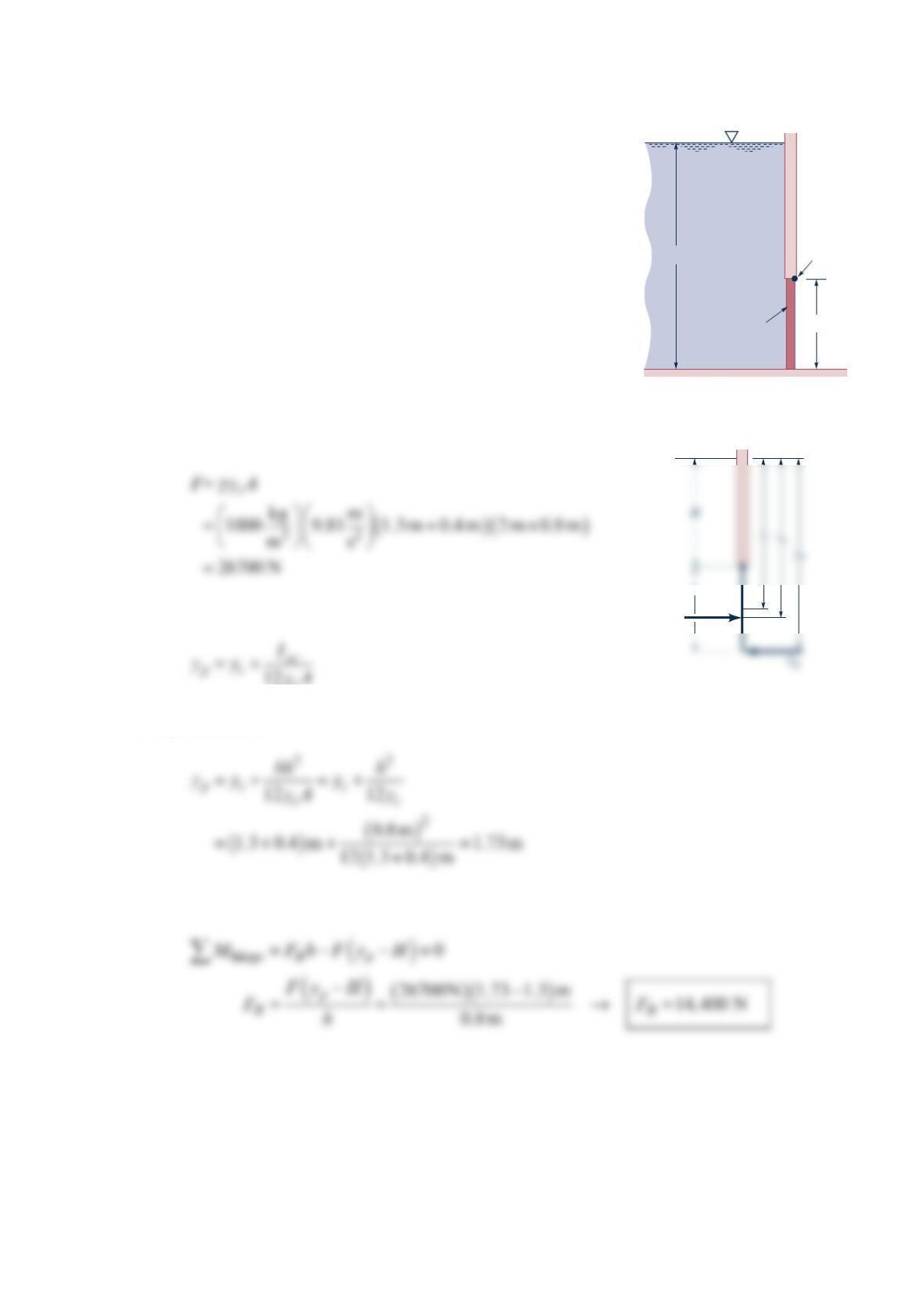
Problem 2.78
An automobile has just dropped into a river. The car door is approximately a rectangle,
measures 36 in. wide and 40 in. high, and hinges on a vertical side. The water level inside
the car is up to the midheight of the door, and the air inside the car is at atmospheric
pressure. Calculate the force required to open the door if the force is applied 24 in. from
the hinge line. See the figure below. (The driver did not have the presence of mind to open
the window to escape.)
Solution 2.78
Note that the force due to atmospheric pressure acts in equal and opposite directions on
two sides of the door. The hydrostatic force on the inside of the door is
The hydrostatic force on the outside of the door is
Summing moments about the hinge line
36′′
4′
40′′
24′′
Fo
Top view of door