Problem 2.79
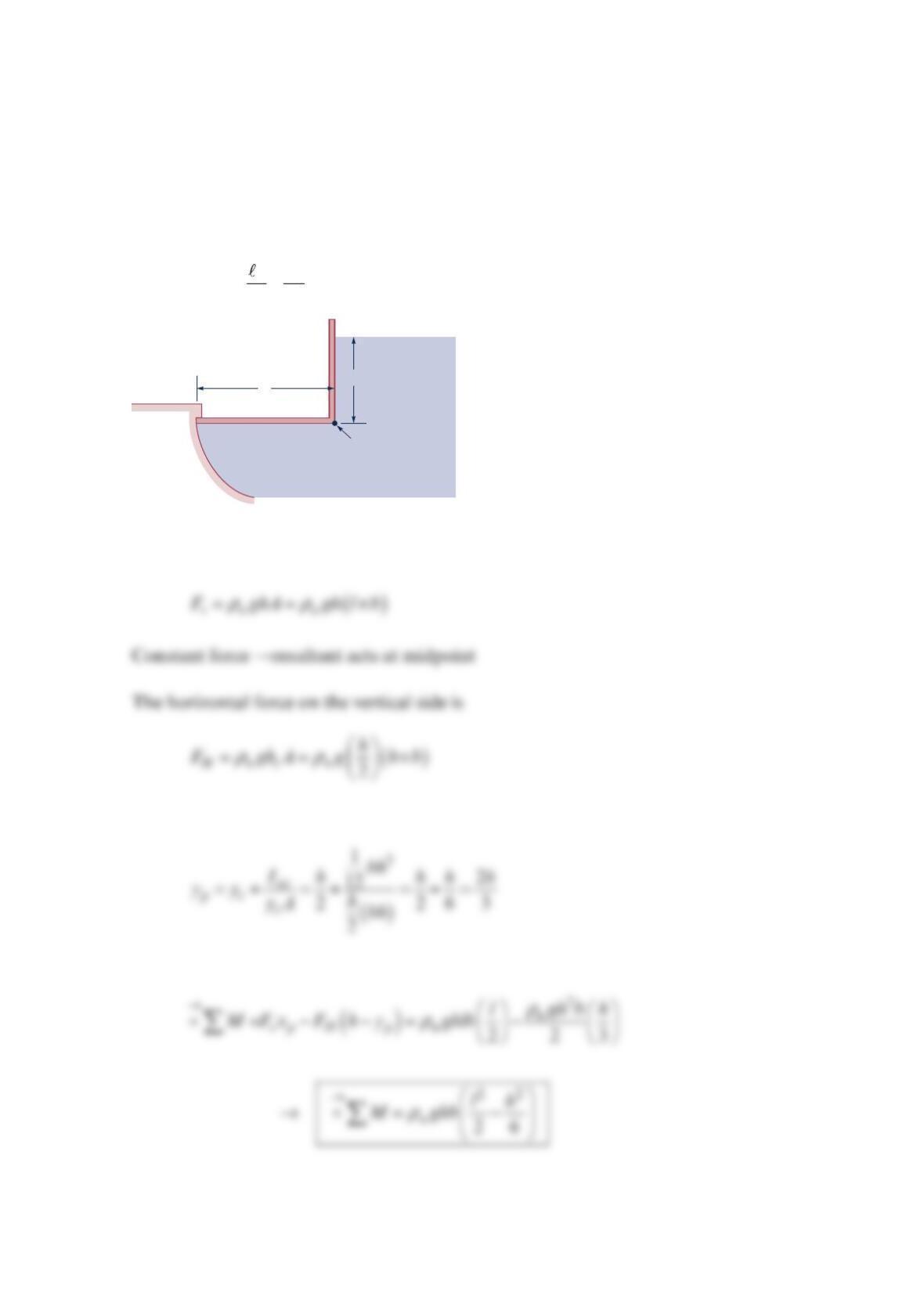
Consider the gate shown in the figure below. The gate is massless and has a width b
(perpendicular to the paper). The hydrostatic pressure on the vertical side creates a
counterclockwise moment about the hinge, and the hydrostatic pressure on the horizontal
side (or bottom) creates a clockwise moment about the hinge. Show that the net clockwise
moment is
ρ
=−
22
26
w
h
u ghb .
Solution 2.79
The vertical force on the horizontal side is
The resultant acts at
Summing moments about the hinge
Water,
pw
Hinge
h
ℓ
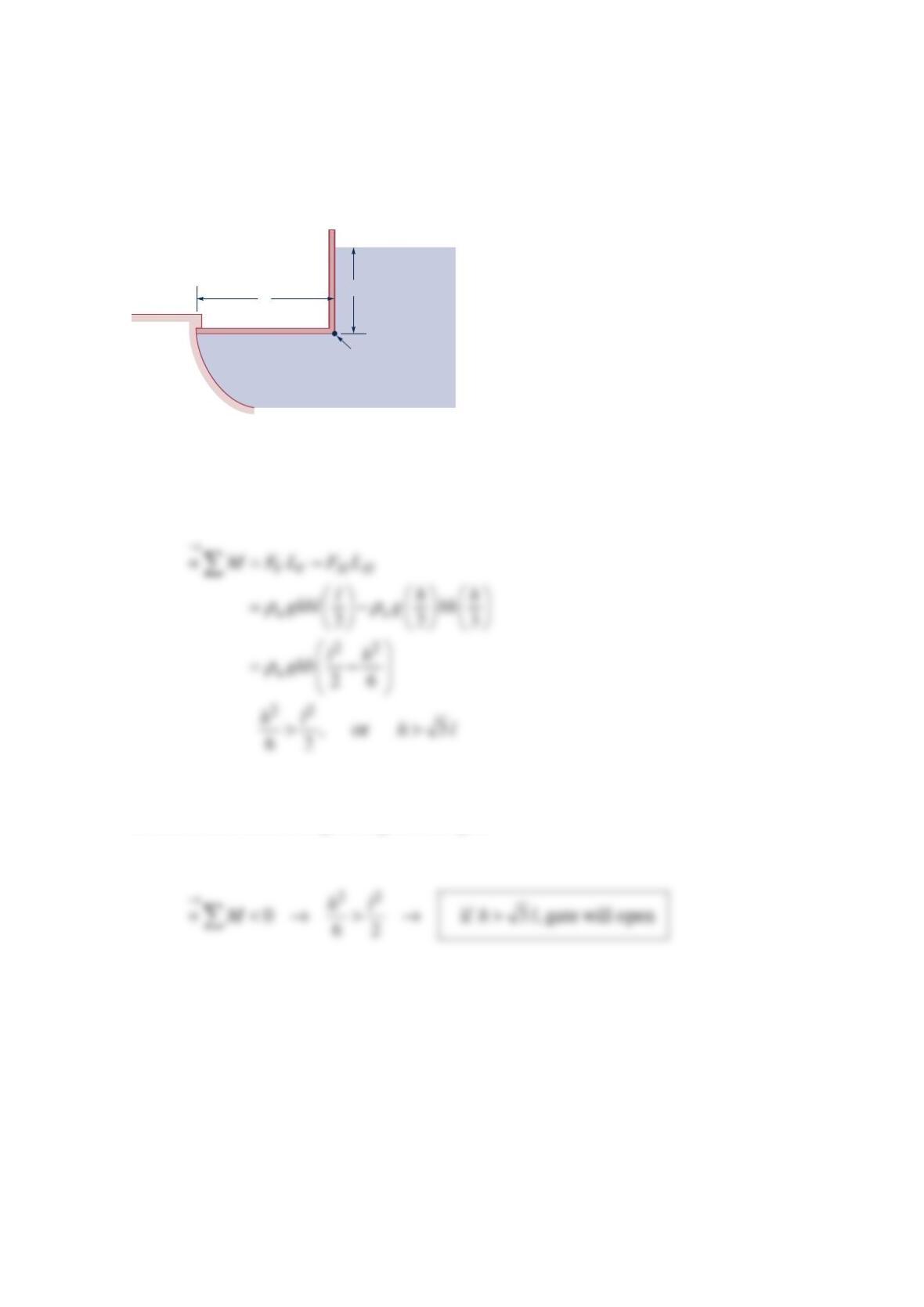
Problem 2.80
Consider the gate shown in the figure below. The gate is massless and has a width b
(perpendicular to the paper). The hydrostatic pressure on the vertical side creates a
counterclockwise moment about the hinge, and the hydrostatic pressure on the horizontal
side (or bottom) creates a clockwise moment about the hinge. Will the gate ever open?
Solution 2.80
Sum moments about hinge
If sum of moments is negative, gate will open
Water,
pw
Hinge
h
ℓ
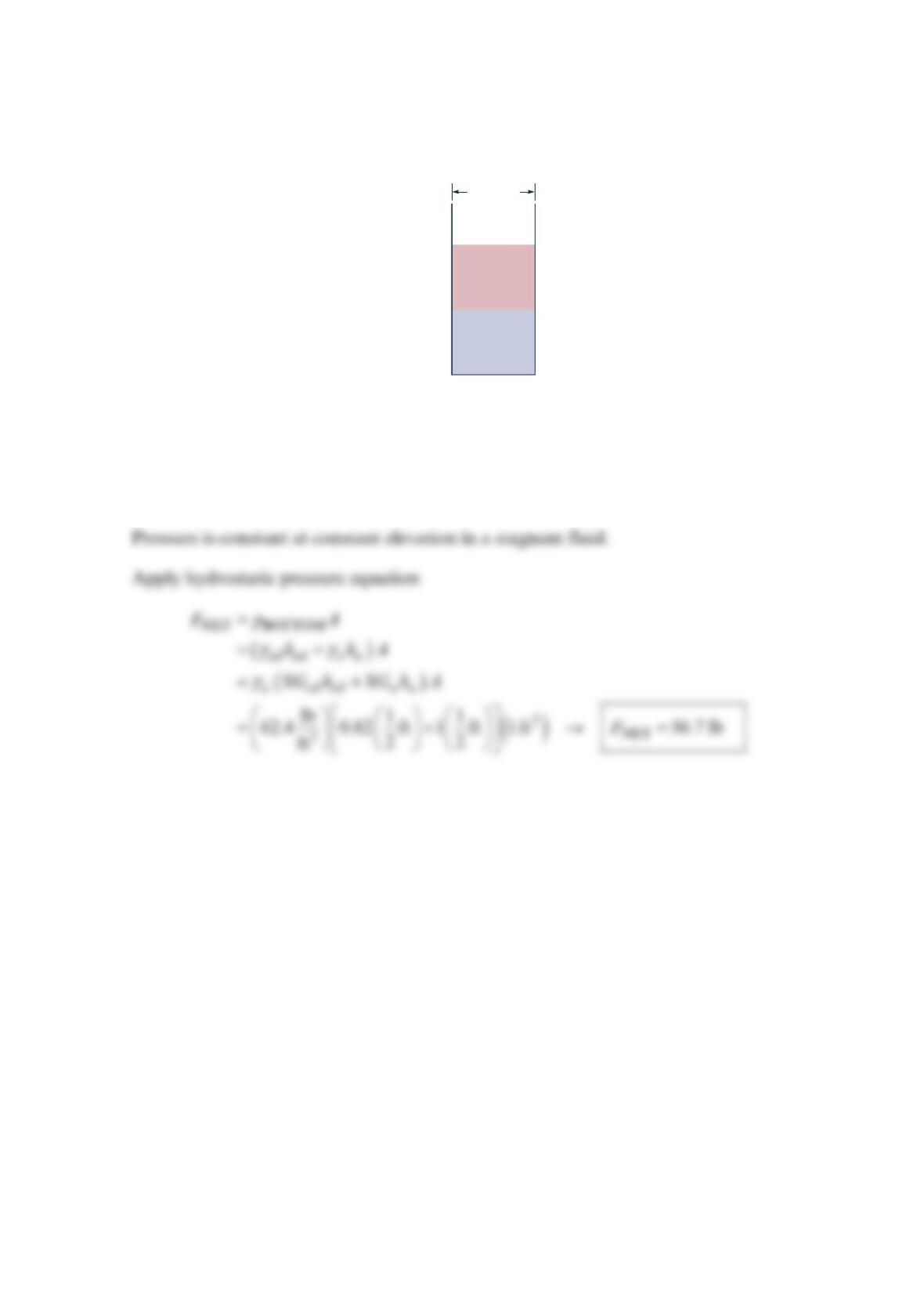
Problem 2.81
A tank contains 6 in. of oil ( =0.82SG ) above 6 in. of water ( = 1. 00SG ). Find the force
on the bottom of the tank. See the figure below.
Solution 2.81
Assume atmospheric pressure acts on outside of tank.
Oil
(
S
= 0.82)
Water
(
S
= 1.0)
A
= 1 ft2
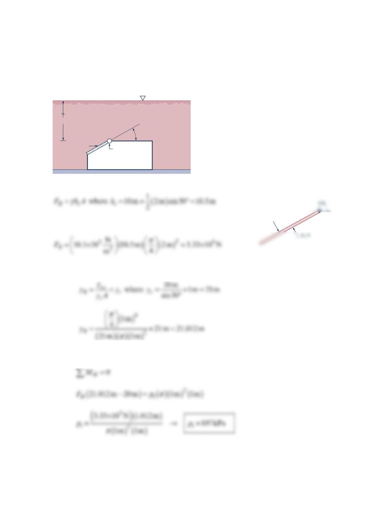
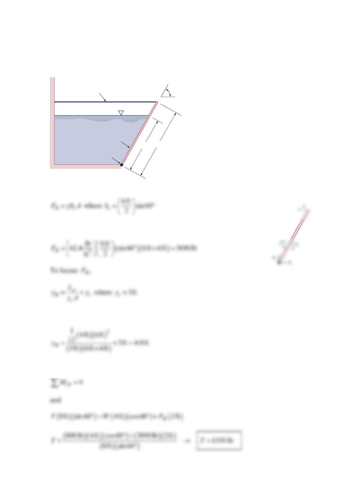
Problem 2.82
A structure is attached to the ocean floor as shown in the figure below. A 2-m -diameter
hatch is located in an inclined wall and hinged on one edge. Determine the minimum air
pressure, 1
p
, within the container that will open the hatch. Neglect the weight of the hatch
and friction in the hinge.
Solution 2.82
Thus,
To locate R
F
,
For equilibrium,
10 m
Free surface
Seawater
Hatch Hinge
Air pressure, p
1
30°
F
R
H
x
Problem 2.83
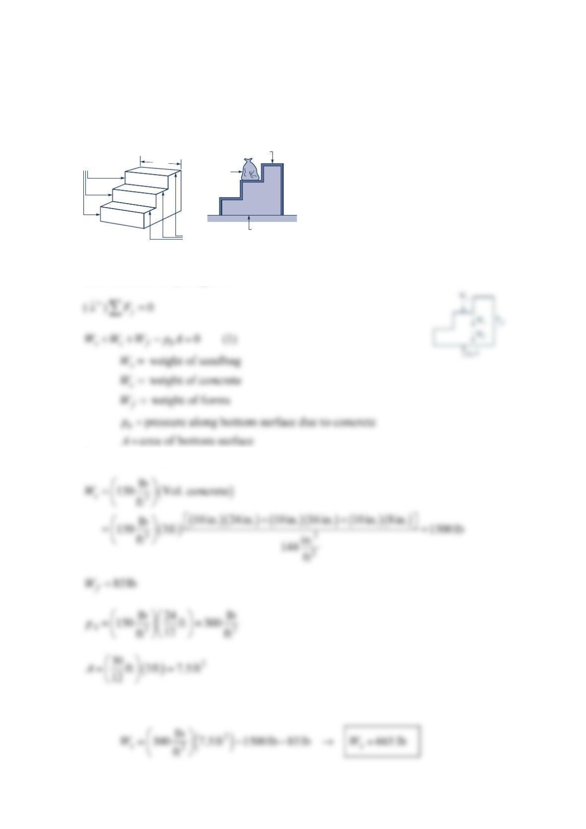
Concrete is poured into the forms as shown in the figure below to produce a set of steps.
Determine the weight of the sandbag needed to keep the bottomless forms from lifting off
the ground. The weight of the forms is85 lb , and the specific weight of the concrete is
3
1
50 lb / ft .
Solution 2.83
From the free-body-diagram
From the data given:
Thus, from Eq. (1)
10 in. tread
Open top
Sand
8 in. risers 3 ft
Open bottom
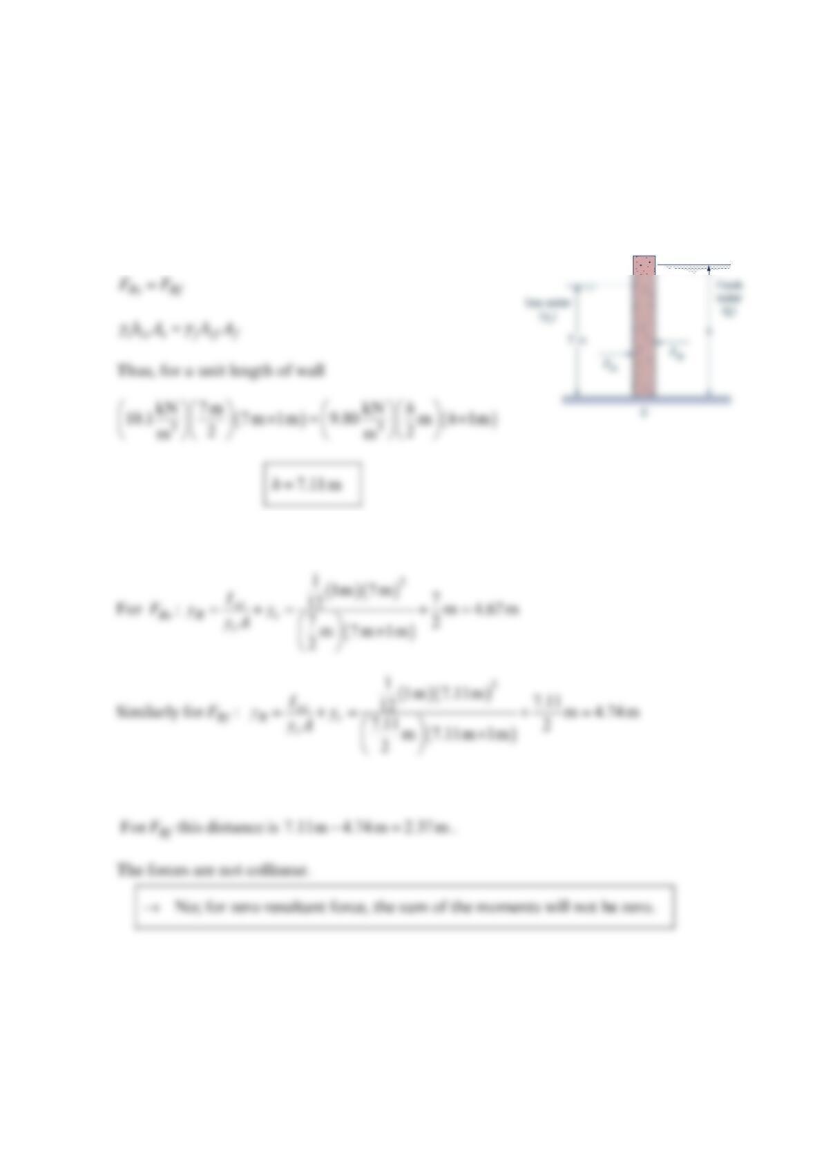
Problem 2.84
A long, vertical wall separates seawater from fresh water. If the seawater stands at a depth
of 7 m, what depth of freshwater is required to give a zero resultant force on the wall?
When the resultant force is zero, will the moment due to the fluid forces be zero? Explain.
Solution 2.84
For a zero resultant force
In order for moment to be zero, Rs
Fand Rf
Fmust collinear.
Thus, the distance to Rs
Ffrom the bottom (point 0) is
7
m 4.67 m 2.33m−=.
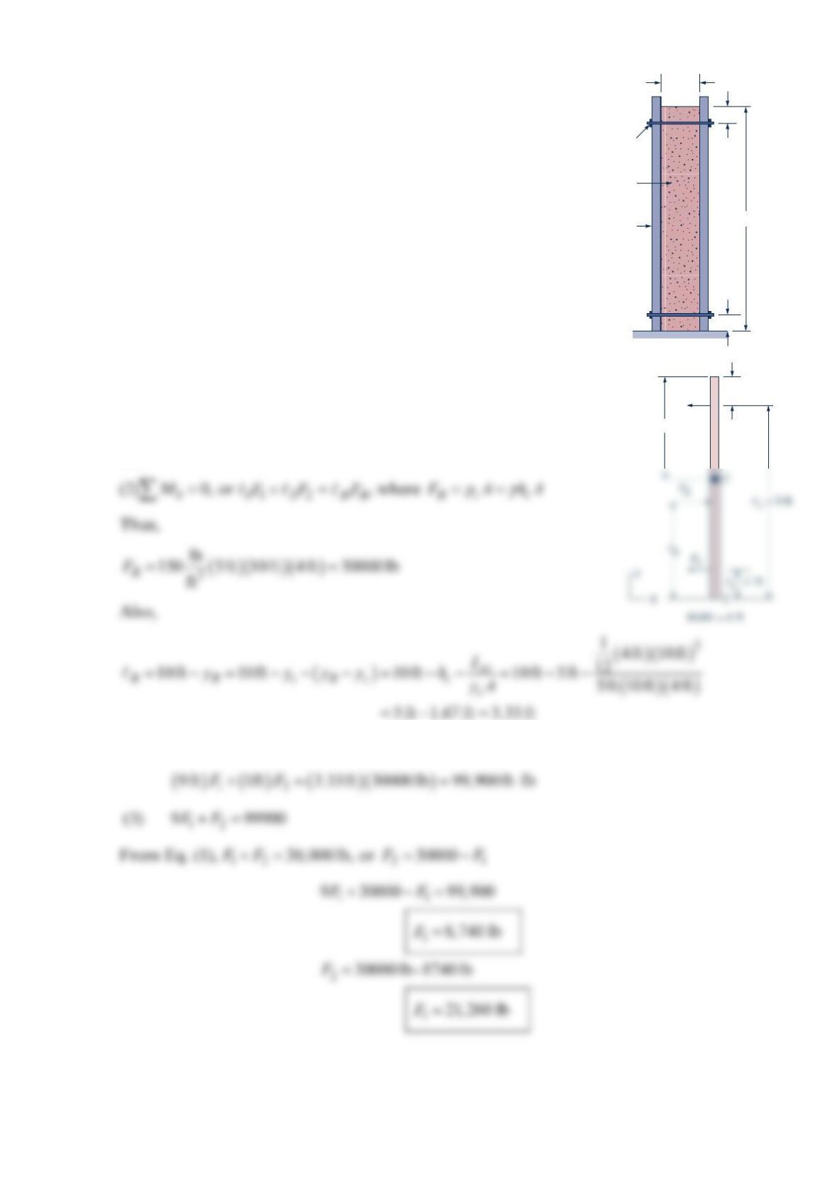
Problem 2.85
Forms used to make a concrete basement wall are shown in the
figure below. Each 4-ft -long form is held together by four
ties—two at the top and two at the bottom as indicated.
Determine the tension in the upper and lower ties. Assume
concrete acts as a fluid with a weight of 3
1
50 lb / ft .
Solution 2.85
(1) 0
x
F=
, or +=
12 R
FF F
and
Thus, from Eq. (2):
Tie
Concrete
Form 10 ft
1 ft
1 ft
10 in.
1 ft
F1
hc = 5 ft
Freshly poured
concrete
Wooden
forms
Hardened
concrete
8 ft
Hardened
concrete
B
C
12 ft
6 ft
8 ft
8 ft
A
5 ft
B
C
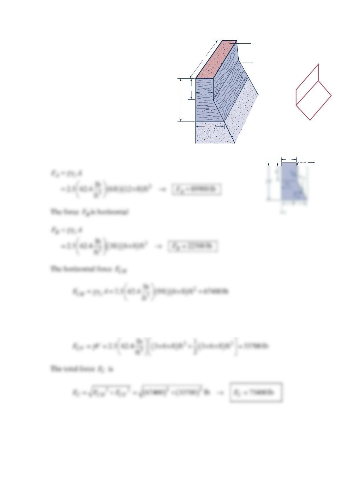
Problem 2.86
While building a high, tapered concrete
wall, builders used the wooden forms
shown in the figure below. If concrete
has a specific gravity of about
2
.5, find
the total force on each of the three side
sections (A, B, and C) of the wooden
forms (neglect any restraining force of
the two ends of the forms).
Solution 2.86
The horizontal force A
F
The vertical force CV
Fis the weight of concrete “above” the slanted side (the dashed
volume)
x
5
′
Problem 2.87
A homogeneous, 4-ft -wide, 8-ft -long rectangular gate weighing 800 lb is held in place by a
horizontal flexible cable as shown in the figure below. Water acts against the gate, which is
hinged at point A. Friction in the hinge is negligible. Determine the tension in the cable.
Solution 2.87
Thus,
so that
For equilibrium,
Cable
Gate
Hinge
Water
6 ft 8 ft
A
60°
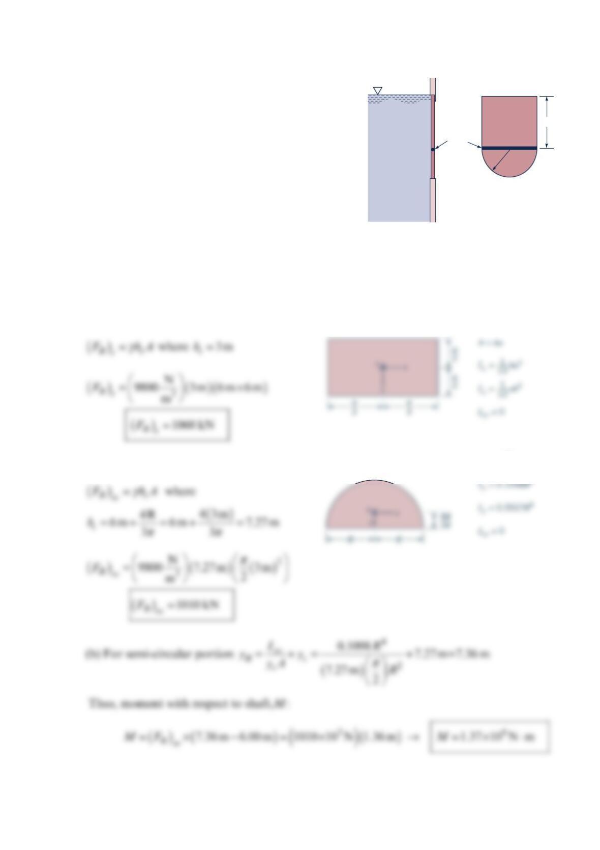
Problem 2.88
A gate having the shape shown in the figure below is
located in the vertical side of an open tank
containing water. The gate is mounted on a
horizontal shaft. (a) When the water level is at the
top of the gate, determine the magnitude of the fluid
force on the rectangular portion of the gate above
the shaft and the magnitude of the fluid force on
the semicircular portion of the gate below the shaft.
(b) For this same fluid depth determine the moment
of the force acting on the semicircular portion of the
gate with respect to an axis that coincides with the shaft.
Solution 2.88
(a) For rectangular portion,
For semi-circular portion,
Shaft
Side view
of gate
Water 6 m
3 m
A = R2
–––––
2
π
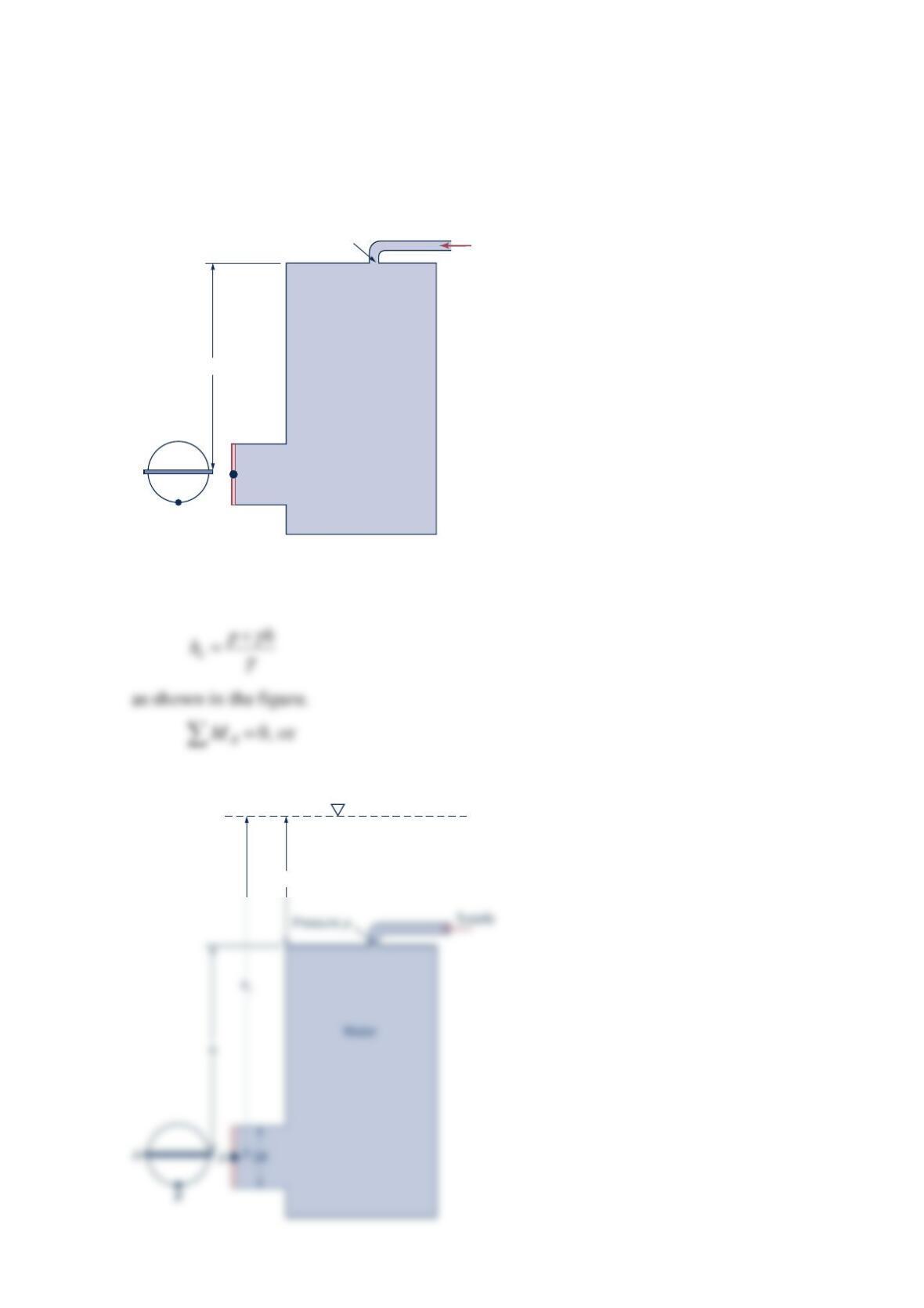
Problem 2.89
A pump supplies water under pressure to a large tank as shown in the figure below. The
circular-plate valve fitted in the short discharge pipe on the tank pivots about its diameter
A–A and is held shut against the water pressure by a latch at B. Show that the force on the
latch is independent of the supply pressure,
p
, and the height of the tank,
h
.
Solution 2.89
The pressure on the gate is the same as it would be for an open tank with a depth of
(1)
()
−=
RcR B
y
yF RF
Water
Supply
Pressure p
h
A
A
B
p/
γ
p
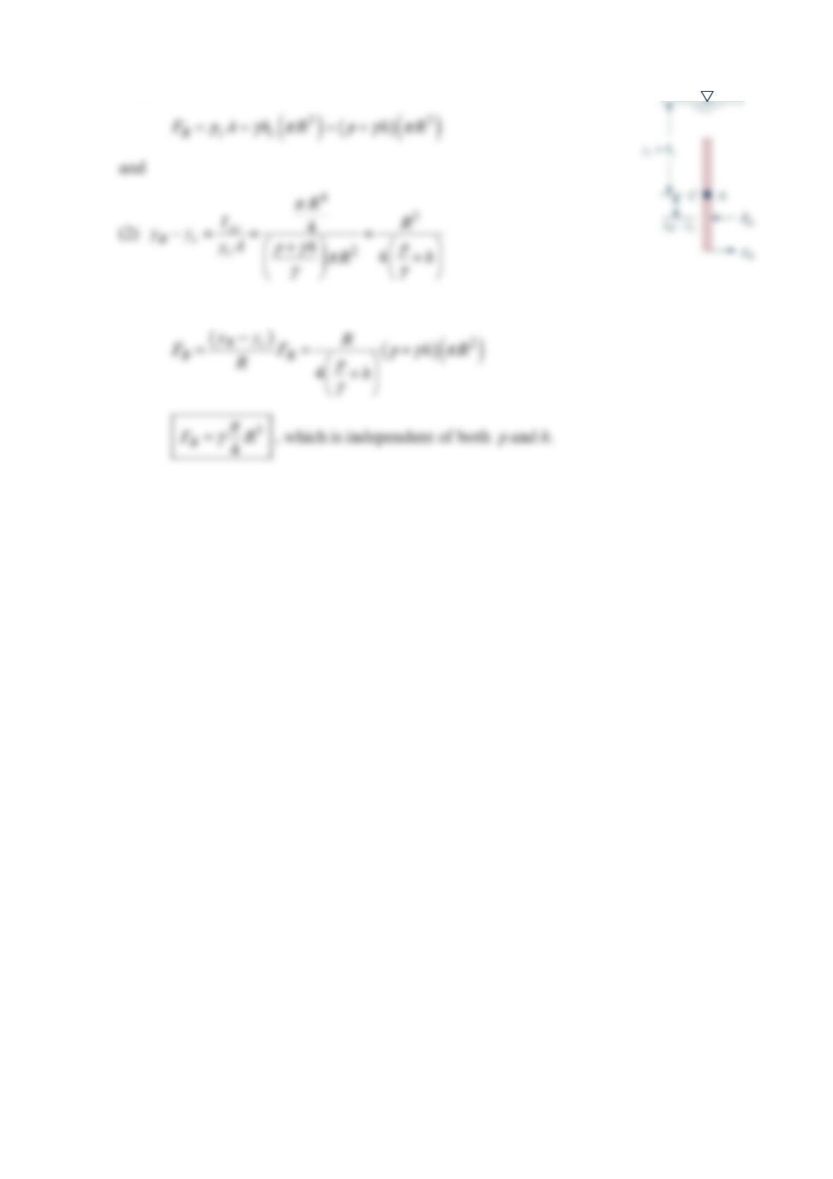
where
Thus, from Eqs. (1) and (2)
Problem 2.91
Find the center of pressure of an elliptical area of minor axis 2a and major axis 2b where
axis 2a is vertical and axis 2b is horizontal. The center of the ellipse is a vertical distance h
below the surface of the water ( >ha). The fluid density is constant. Will the center of
pressure of the ellipse change if the fluid is replaced by another constant-density fluid? Will
the center of pressure of the ellipse change if the vertical axis is tilted back an angle
α
from
the vertical about its horizontal axis? Explain.
Solution 2.91
For a hydrostatic pressure distribution, using geometric information from the Appendix,
Recognizing symmetry about minor axis,
Above expressions for
p
xand
p
y
contain only geometric properties (and not fluid
properties)
The equation
y
2
b
x
Problem 2.92
The dam shown in the figure below is 200 ft long and is made of concrete with a specific
gravity of
2
.2. Find the magnitude and y coordinate of the line of action of the net
horizontal force.
Solution 2.92
The headwater horizontal force and its line of action are
The tailwater horizontal force and its line of action are
The line if action is located by taking moments about the
base of the dam.
X
60′
20′
20′
Headwater
Tailwater
40′
y
g
60′–
yHP
= 20′
= 6.7′
Problem 2.93
The dam shown in the figure below is 200 ft long and is made of concrete with a specific
gravity of 2.2 . Find the magnitude and x coordinate of the line of action of the vertical
force on the dam resulting from the water.
Solution 2.93
The only vertical force due to the water is on the headwater side of the dam. This vertical
force equals the weight of the water above the surface and the force acts through the
X
60′
20′
20′
Headwater
Tailwater
40′
y
g
Problem 2.94
The figure below is a representation of the
Keswick gravity dam in California. Find the
magnitudes and locations of the hydrostatic
forces acting on the headwater vertical wall
of the dam and on the tailwater inclined wall
of the dam. Note that the slope given is the
ratio of the run to the rise. Consider a unit
length of the dam ( =1ftb).
Solution 2.94
Consider a unit length of the dam. The headwater force is
The location p
y
is
The tailwater force is
The location ′
p
y
is
El. 595.00′
Headwater
Tailwater
21.5′
100′
30′
El. 565.40′
Slope – 0.7:1
El. 491.00′
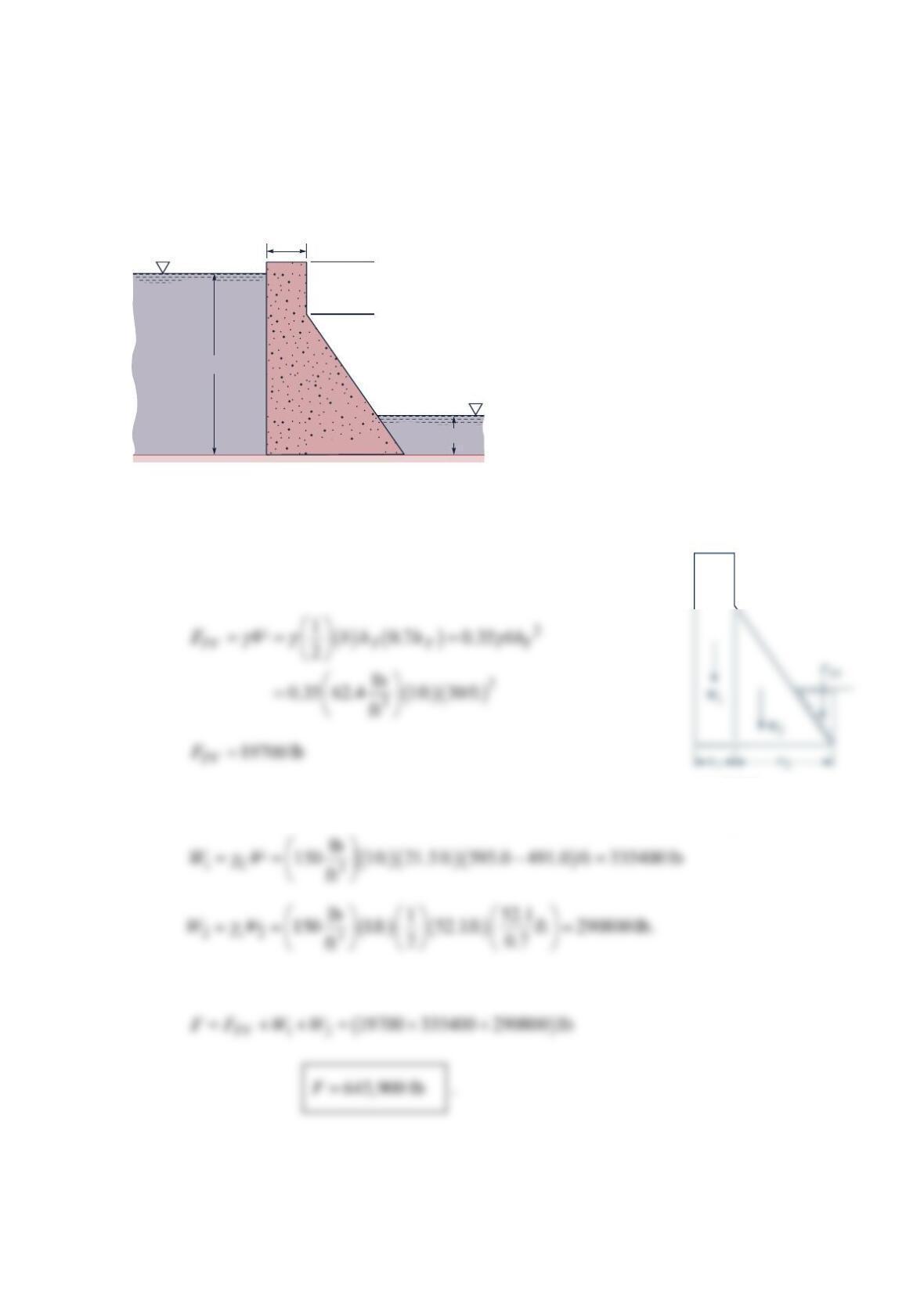
Problem 2.95
The Keswick dam shown in the figure below is made of concrete and has a specific weight
of 3
1
50lb/ft . The hydrostatic forces and the weight of the dam produce a total vertical force
of the dam on the foundation. Find the magnitude and location of this total vertical force.
Consider a unit length of the dam =(1 ft).b
Solution 2.95
The hydrostatic vertical force is due to the tailwater. Its magnitude
for a dam unit length is
The dam weight consists of +
12
WW. Now
The total force F is
El. 595.00′
Headwater
Tailwater
21.5′
100′
30′
El. 565.40′
Slope – 0.7:1
El. 491.00′
w
1
= 21.5 ft.
w
2
= 0.7(565.4 – 491.0) ft
= 52.1 ft.
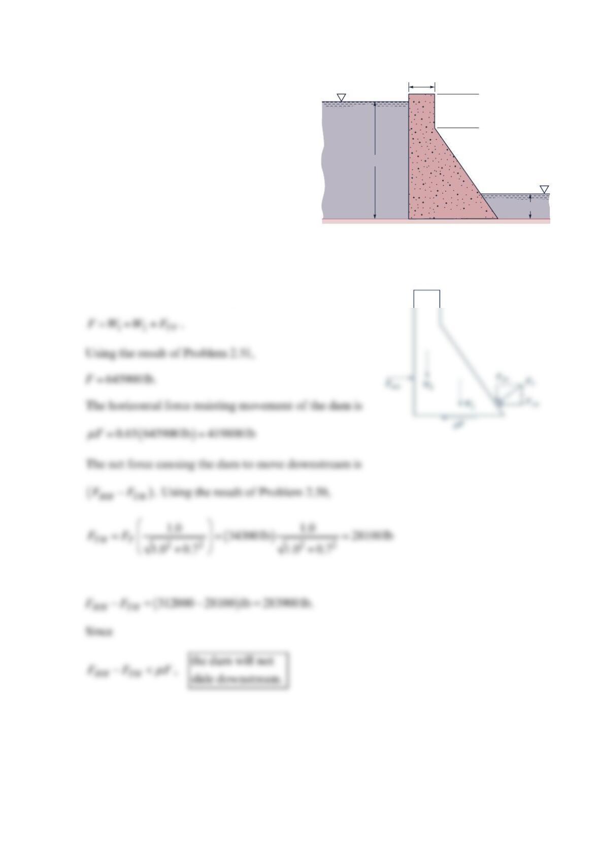
Problem 2.96
The Keswick dam shown in the figure
below is made of concrete and has a specific
weight of 3
150lb/ft . The coefficient of
friction
µ
between the base of the dam and
the foundation is 0.65 . Is the dam likely to
slide downstream? Consider a unit length of
the dam ( =1 ftb).
Solution 2.96
The total vertical force acting downward is
Then
µ
El. 595.00′
Headwater
Tailwater
21.5′
100′
30′
El. 565.40′
Slope – 0.7:1
El. 491.00′
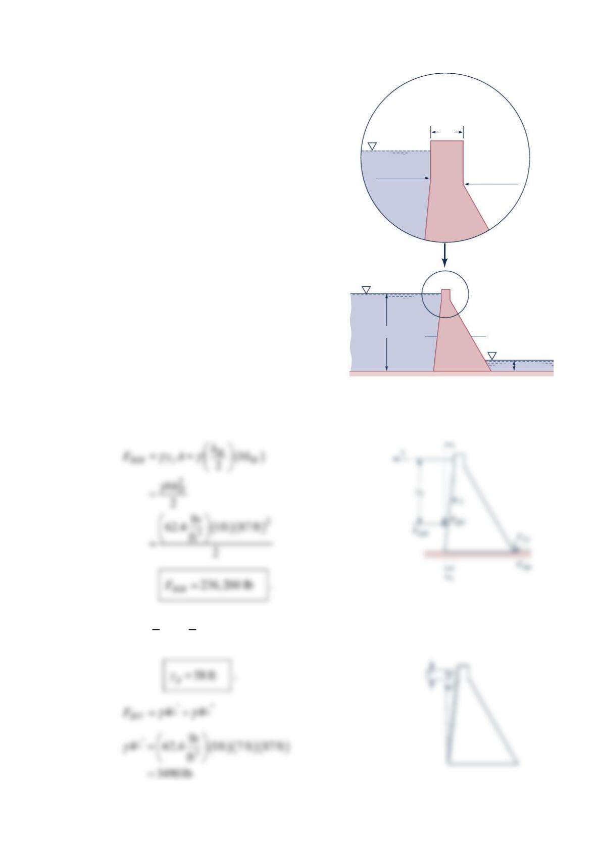
Problem 2.97
The figure below is a representation of the Altus
gravity dam in Oklahoma. Find the magnitudes
and locations of the horizontal and vertical
hydrostatic force components acting on the
headwater wall of the dam and on the tailwater
wall of the dam. Note that the slope given is the
ratio of the run to the rise. Consider a unit length
of the dam =( 1ft).b
Solution 2.97
First consider the headwater hydrostatic force components.
()
==
22
87 ft
33
pH
yh
()
=−
10.1 1555.0 1475.0 ft
=8ft.
w
Headwater
10′
87′
4′
Tailwater
Slope =
0.1:1
EI. 1553.00′
EI. 1555.00′
EI. 1564.00′
Slope = 0.6:1
EI. 1475.00
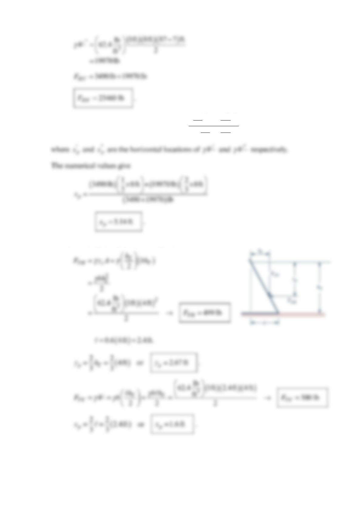
The location p
x of HV
F is found from
γ
=
‘
p
V
x
γ
+
”‘
p
xV
γ
”
‘
p
x
V
γ
+”
V
The tailwater hydrostatic force components