
Chap. 19 Deep Foundations: Axial Load Capacity Based on Dynamic Methods
19.1 Explain why pile–driving formulas are not reliable, and why a wave equation analysis is a better
choice.
Solution
Pile-driving formulas have proven to be very inaccurate because they do not properly account for

Chap. 19 Deep Foundations: Axial Load Capacity Based on Dynamic Methods
19.2 Under what conditions will tensile stresses be generated in pile driving in what situations should
this be of a concern?
Solution
Tensile stresses will be generated when the compression wave in the pile reflects off a boundary
with a lower impedance (lower wave speed) than that of the pile. This will occur at the bottom

Chap. 19 Deep Foundations: Axial Load Capacity Based on Dynamic Methods
19.3 What’s the difference between a hammer cushion and a pile cushion? What are the purposes of
each? Under what circumstances is a pile cushion generally used?
Solution
A hammer cushion is placed between the anvil and the helmet and is designed to reduces stresses
in and prevent damage to the ram when it impacts the anvil. Hammer cushions are generally
Chap. 19 Deep Foundations: Axial Load Capacity Based on Dynamic Methods
19.4 Two different single acting hammers are being considered for an open ended pipe pile. Hammer
A has a ram weight of 30 kN and a stroke of 3 m. Hammer B has a ram weight of 15 kN and
stroke of 5 m. Both hammers use similar appurtenances. Which hammer will deliver the most
energy to the pile? Which hammer will generate the highest stresses in the pile?
Solution
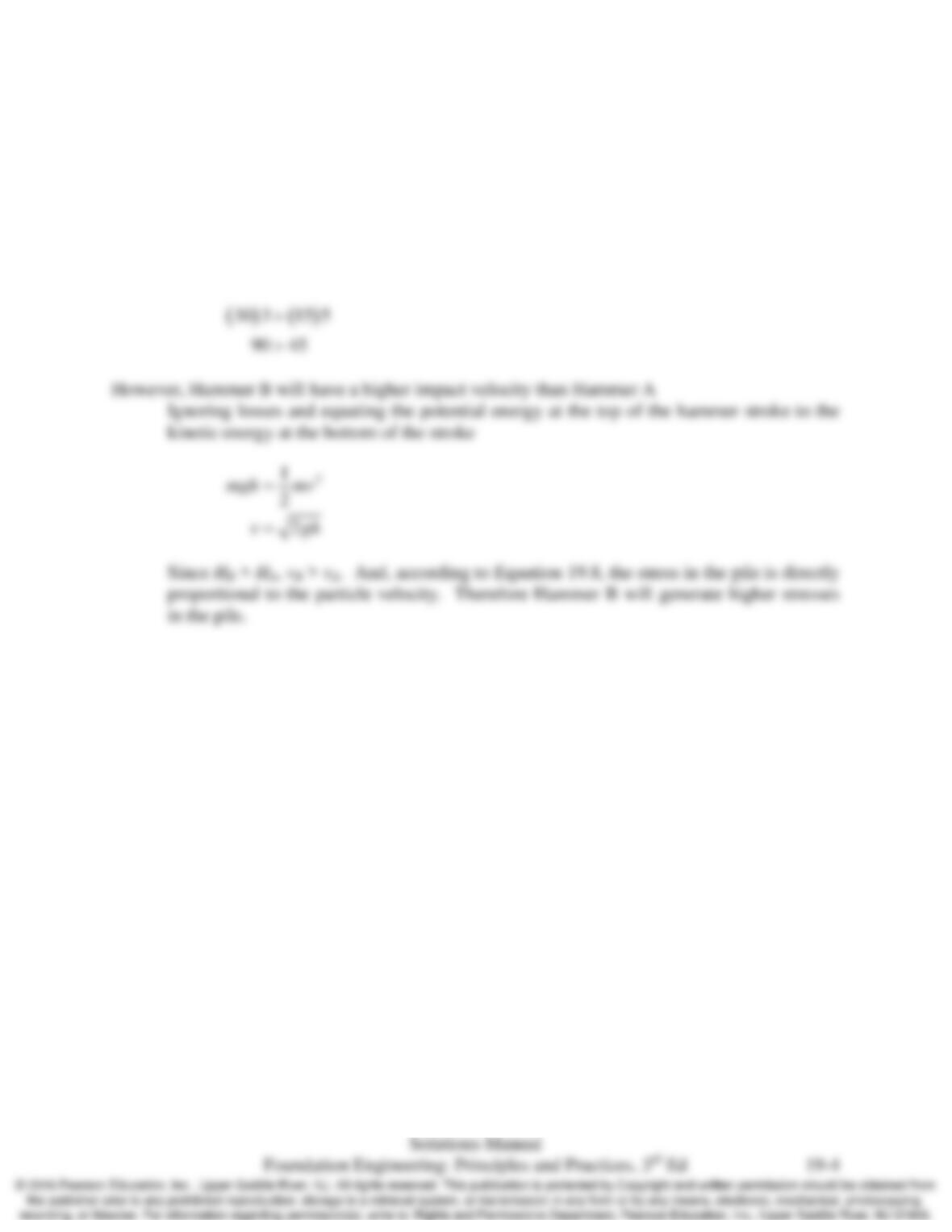
Hammer A clearly generates greater energy than Hammer B
Chap. 19 Deep Foundations: Axial Load Capacity Based on Dynamic Methods
19.5 A 15–m long normal weight concrete pile is being driven at a rate of 25 blows per minute. Will
the wave from the first hammer blow reach the bottom of the pile and return to the top before the
next hammer blow? Justify your answer with appropriate computations and comment on the
results.
Solution
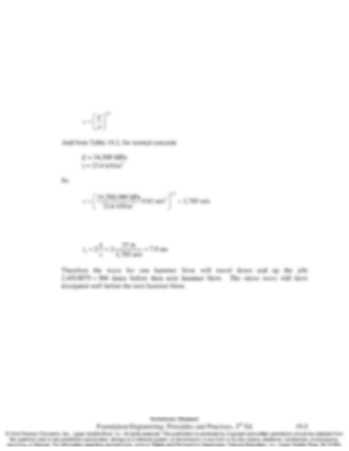
Per Equation 19.6, the wave speed in the pile will be
The time between hammer blows is 60/25 = 2.4 s. And the travel time down the pile and
back up is

Chap. 19 Deep Foundations: Axial Load Capacity Based on Dynamic Methods
19.6 A building is to be constructed on driven piles. The downward vertical load on each pile based
on ASD load combinations is 120 k with a factor of safety of 2.5. Estimate the rated hammer
energy required to drive these piles.
Solution
With a design load of 120 k and a factor of safety of 2.5, the piles will have to be driven to a
Chap. 19 Deep Foundations: Axial Load Capacity Based on Dynamic Methods
19.7 Driven piles will be used to support a bridge founded on a deep sand deposit. The factored
downward axial structural load for piles in the foundation is 380 kN. Determine the required
nominal capacity of the piles, Pn, for the following analysis and testing procedures. Use
AASHTO resistance factors provided in Tables 13.3 and 13.4.
a) Only static analysis using the β method
b) Static analysis combined with wave equation analysis but neither dynamic pile
measurements nor static load test.
c) A static load test on one pile plus at CAPWAP analysis on at least two piles.
Comment on the value of wave equation analysis, load testing, and CAPWAP analysis for this
pile design.
Solution
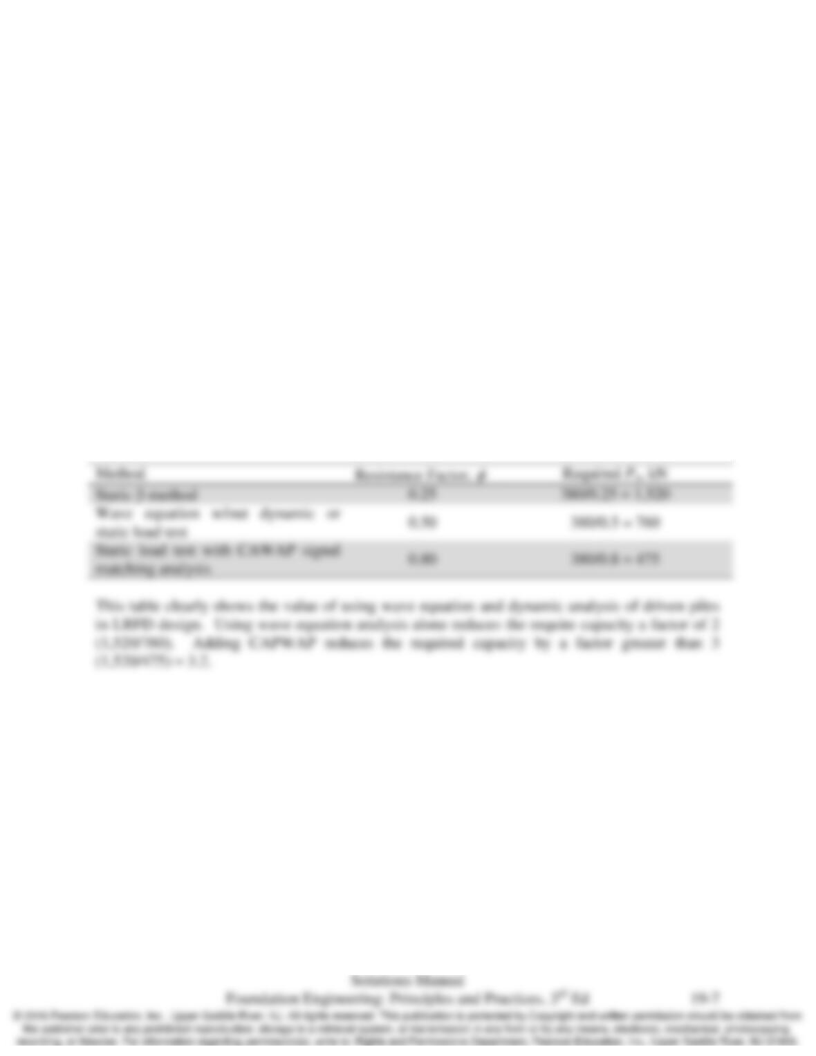
The required static pile capacity for an LRFD design is Pu/
φ
, where
φ
is the appropriate
resistance factor. Using the resistance factors from Tables 13.3 and 13.4, the required static
capacity for the three methods
Chap. 19 Deep Foundations: Axial Load Capacity Based on Dynamic Methods
19.8 The bearing graph shown in Figure 19.6 was developed for an FEC model 1500 open ended
diesel hammer driving closed ended pipe pile 19 m into a sand deposit. The pile has an outside
diameter of 35.6 cm and wall thickness of 80 mm made with A–252 grade 2 steel (fy = 240 MPa).
The required ultimate static pile resistance, Rur, is 1000 kN. On site, a certain pile was driven to
19 m with a blow count of 50 for the last 0.25 m. Assume the setup factor is 1.0, will this pile
meet the required capacity? Will the driving stresses be acceptable?
Solution
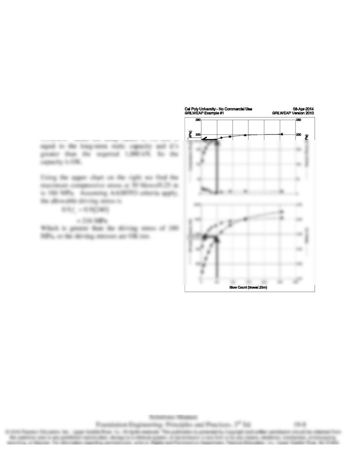
The final blow count during driving is 50 per
0.25m. Entering the bearing graph (lower chart
on right) at 50, we get a static capacity of

Chap. 19 Deep Foundations: Axial Load Capacity Based on Dynamic Methods
19.9 A 14–inch square prestressed concrete pile is to be driven with a certain hammer. According to a
wave equation analysis, the compressive driving stresses will exceed the maximum allowable
values described in Table 19.7. What can be done to resolve this problem? Provide at least two
possible solutions.
Solution
A thicker pile cushion will reduce the peak stresses in the pile, but there is a limit to how thick a
Chap. 19 Deep Foundations: Axial Load Capacity Based on Dynamic Methods
19.10 Explain how wave equation analysis combined with static or dynamic load tests can be used to
determine the long term capacity of piles driven in clay where there is a significant setup factor.
Solution
The wave equation analysis computes the static resistance during driving. Similarly, a
CAPWAP or similar short–duration high strain dynamic test will also determine the static
resistance during driving. For a clay soil with significant setup, the static resistance during
driving will be much less than the long–term static resistance achieved after setup. There are

Chap. 19 Deep Foundations: Axial Load Capacity Based on Dynamic Methods
19.11 Why does the Statnamic test use a relatively slow burning propellant rather than high explosive
to provide the energy for the test?
Solution
There are two problems with high explosives. First, they generate extremely high stresses and
would destroy the Statnamic test device. Second, they would generate a very short stress pulse.

Chap. 19 Deep Foundations: Axial Load Capacity Based on Dynamic Methods
19.12 Perform a wave equation analysis for the pile describe in Example 15.4. Select a suitable
hammer that can drive the pile efficiently. You will have to select a wall thickness for the 16
inch diameter pipe and check the driving stresses to ensure they are acceptable. Create a bearing
graph for hammer you selected assuming a setup factor of 2. Also perform a driveability
analysis for the hammer you have selected.
Solution
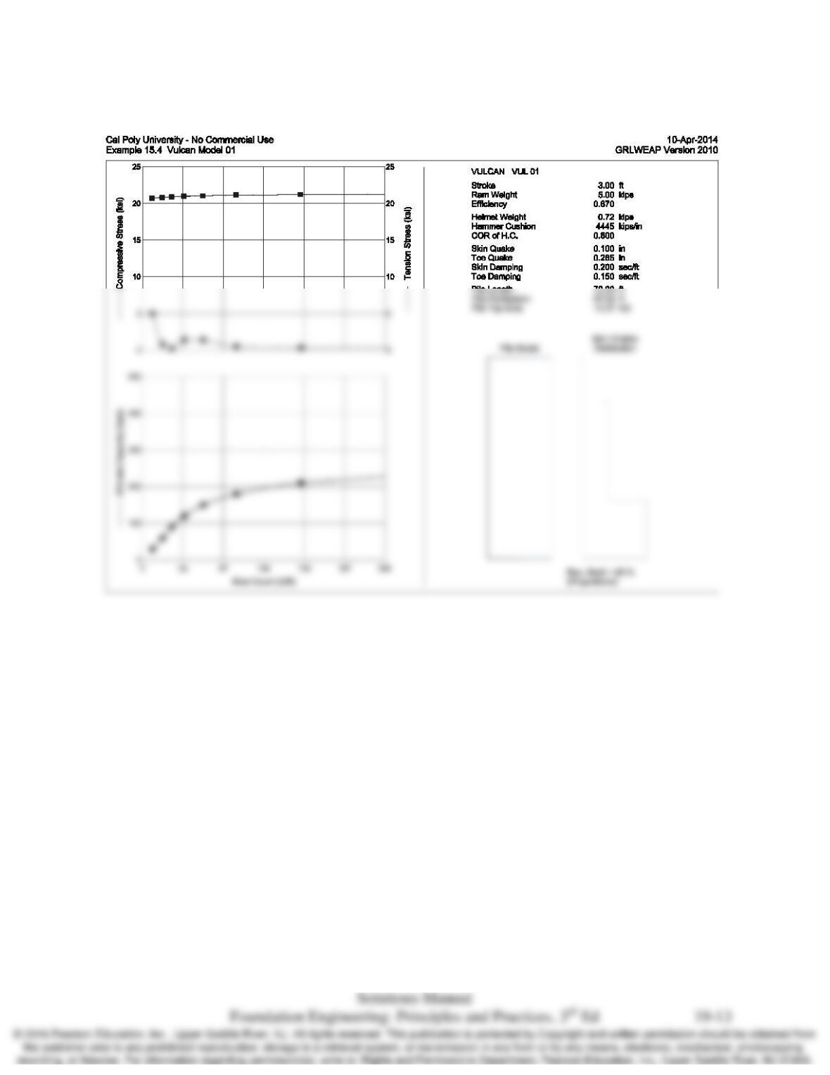
There are a number of solutions to this problem and many pile hammers that can effectively and
efficiently drive this pile. The solution below uses a 16 inch diameter closed end steel pipe with a
Chap. 19 Deep Foundations: Axial Load Capacity Based on Dynamic Methods
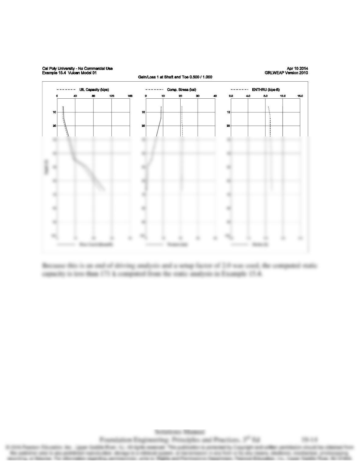
Results of bearing analysis
Chap. 19 Deep Foundations: Axial Load Capacity Based on Dynamic Methods
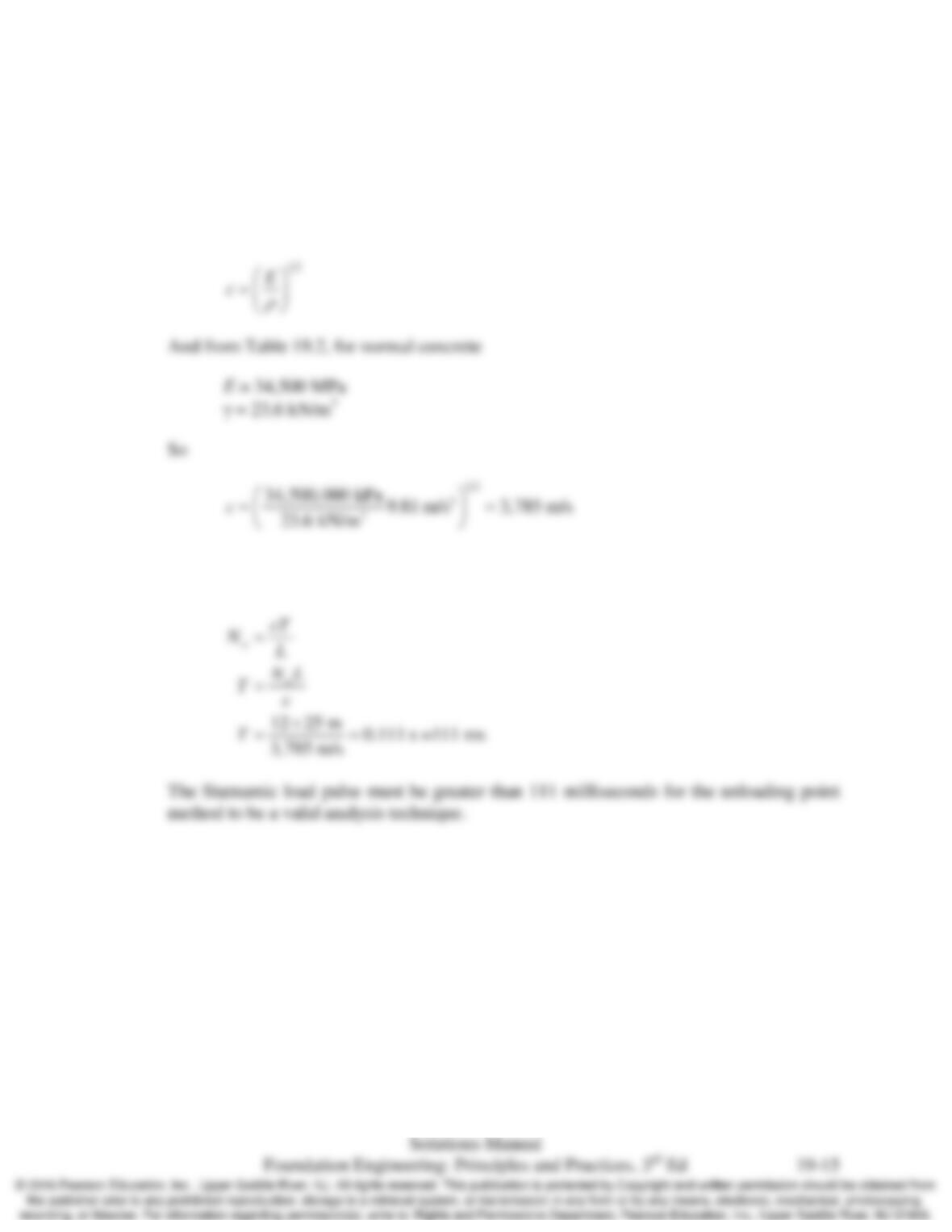
Results of driveability analysis
A setup factor of 2.0 was used for side resistance and 1.0 for toe resistance.
Chap. 19 Deep Foundations: Axial Load Capacity Based on Dynamic Methods
19.13 You wish to perform a Statnamic test on a 35 m long 0.5 m diameter concrete drilled shaft. How
long must the loading pulse be in order to use the Unloading Point Method to analyze the test?
Solution
Per Equation 19.6, the wave speed in the pile will be
For the unloading point method to be valid, the stress wave number, Nw, must be greater
than 12 per Table 19.8